
Universidade Fernando Pessoa
Porto, Portugal
Turbidite Systems
in
Hydrocarbon Exploration
The time of slope fan deposition is a time of major headward erosion and bank collapse of the submarine canyons. Actually, basin subsidence begins to create a very slow rise in the position of the sea level relative to the basin margin, as the rate of eustatic sea level fall slows and approaches zero at the lowest part of the eustatic cycle. Seismic expression of the slope fan (figs. 47 and 48) varies widely:
a) Externally, the fan appears as a broad thick apron of sediments with the thickest and crestal position linked to the source supply, often a submarine canyon.
b) Internally, recognizable seismic facies patterns include slumped deposits from delta and adjacent flanks, the typical “gull wing” pattern of submarine channels and a discontinuous pattern associated with overbank sands near the crest of the slope fan.
Submarine channel sands make excellent exploration targets, particularly if they are identifiable seismically due to gas saturation. Overbank sands are thin, often below the resolution of the conventional logging tools, but their porosity and permeability may be startling high. Overbank sands are apparently created when the supply to a submarine channel exceeds the transport capacity of that conduit and sands well up over the levee and are widely spread in a thin sheet over the slope fan apron. Overbank sands appear to trap against the levee facies, or channel fill shales (clay-plug). In thick accumulations overbank sands may form a very large stratigraphic trap composed of many thin sands. A high level of petrophysical and well testing technology is needed to recognize and properly evaluate such a trap.
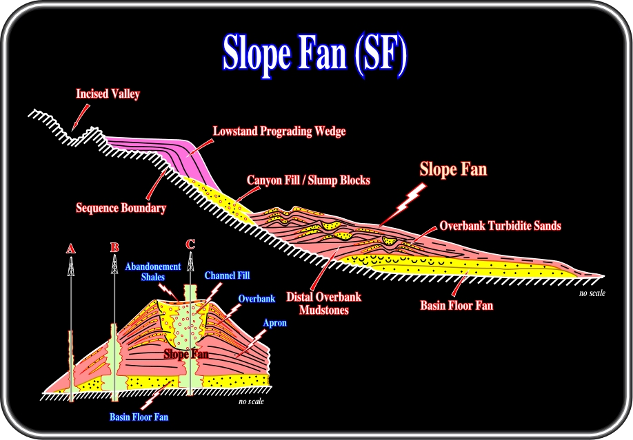
Fig. 47- This geological model (modified from Vail, 1989) summarizes the chief characteristics of a lowstand systems tract (LST) and particularly those of a slope fan (SF), in which channel levee complexes are paramount. In a slope fan, reservoir predictions require a good understanding of the depositional model of channel levees. The main reservoir rocks are localized in the channel fills. The reservoirs in the overbank deposits are quite thin but widespread. When slope fans are the main reservoir interval, explorationists must employ very good seismic data, if possible 3D, in order to predict the most likely location of channel fills, where the thickness and lateral coalescence of the reservoir-rocks is large enough to trap economic amounts of hydrocarbons
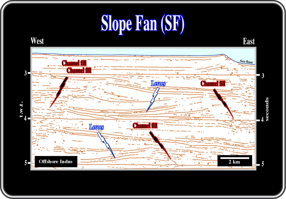
Fig. 48- The picking of seismic reflectores of a seismic line from the offshore Indus illustrates the strike geometry of channel-levee complexes, which are the principal depositional systems of a slope fan where potential siliciclastic reservoir-rocks can be found. However, outwardly, the presence of sandstone reservoir depends exclusively on the lithologic composition of the turbiditic currents. In this particular area, the channel-levee complexes are shale prone. Indeed, taking into account the geological setting of the shelf and nearby onshore, it is quite logical to assume that the potential turbidite currents will be mainly composed by shaly sediments. Actually, the absence of differential compaction, particular above the channel fills (filling of the central conduits) strongly suggests a predominant shaly facies.
On electrical logs (SP, Gamma ray, Resistivity, Sonic, etc.), slope fans exhibit a typical cylindrical pattern as illustrated in fig. 51, that is to say, cylindrical and abrupt boundary in the sandprone channel (quite similar to a basin floor) and "nervous" log character in the overbank complexes, which underlies an alternation of upward thickening and thinning stratigraphic intervals (turbiditic levees).
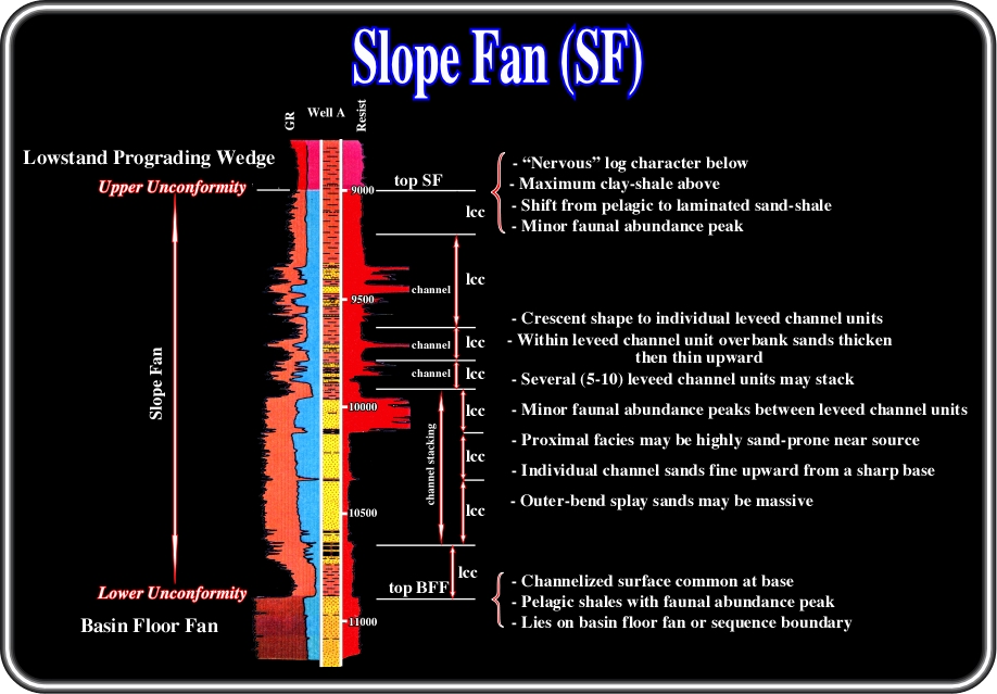
Fig. 49- These electrical logs, from a North Sea well, summarizes the main characteristics of the log patterns of slope fans. A channel fill and particularly a stacking of channel fills may be underlined in a gamma ray or SP log by a blocky shape with a particularly sharp upper boundary. On the contrary, channel levee complexes often induce a typical nervous log response. Stacking of channel fills, when overlying a basin floor fan, are often difficult to recognize on electrical logs particularly when the apron shales, which generally are at the base of a slope fan, are absent.
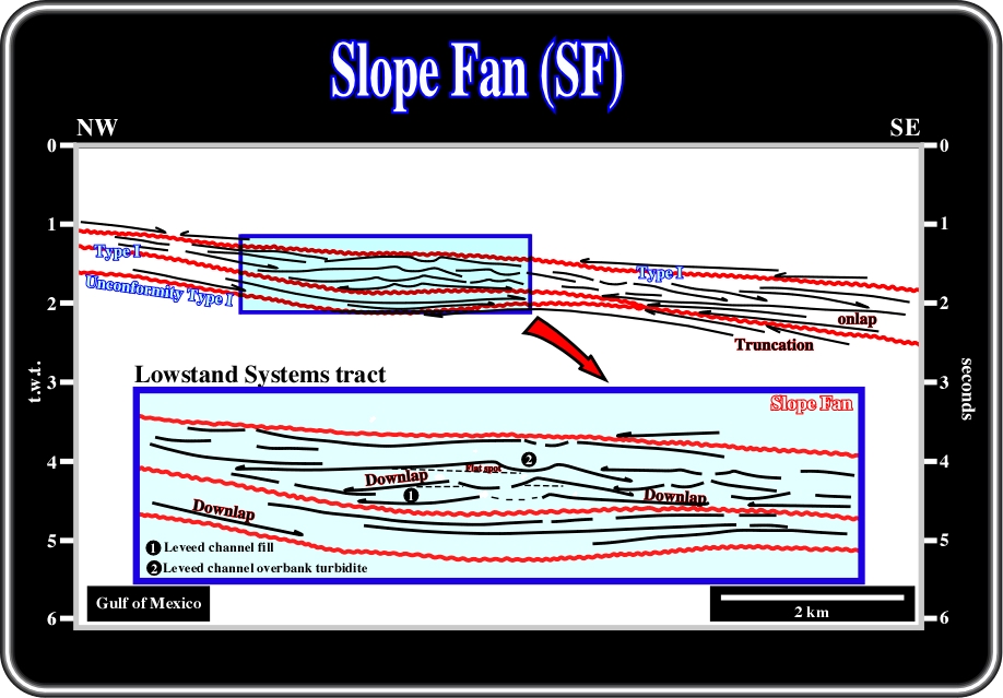
Fig. 50- In the Gulf of Mexico, explorationists are often looking for slope fans, particularly channel levee complexes, as potential hydrocarbon reservoirs. In the majority of cases, explorationists identify these potential reservoirs, when seismic anomalies, as bright spots or flat spots, result from significant hydrocarbon saturation. However, they forget that only a detailed sequential stratigraphy of the seismic lines and calibration of wells allows the prediction of the actual geometry of such reservoirs, and their fluid content. The geometrical relationships between the chronostratigraphic lines, i.e., reflection terminations and seismic surfaces, between 1 and 2.5 seconds of a seismic line from Gulf of Mexico are depicted above. Three sequence-cycle boundaries, associated updip with type I unconformities, limit the lowstand systems tracts of two sequence-cycles. The upper one is mainly composed of the middle lowstand member (slope fan), in which channel-levee complexes are predominant. In terms of potential hydrocarbon reservoirs, one can say they are most likely thin sandstone layers of the overbanks, since the morphology of the central conduit suggests a shaly fill.
As said previously (fig. 50), slope fans have a substantial petroleum interest not only as potential reservoirs but as potential morphological and stratigraphic traps as well (fig. 51). Indeed, their exploration applications can be summarized as follows:
(a) Reservoir
- 5-40 meter sands in channels
- Channel sands discontinuous
- Thin (1-300 cm) sands in overbank facies
- Overbank sands may be quite widespread
- Overbank sands difficult to recognize and evaluate(b) Migration
- Uncertain, probably vertical via fault conduits or from BFF
(c) Source
- Uncertain, probably deep
(d) Trap
- Typically stratigraphic
- Some structural enhanced(e) Seal
- Interval shale seals
- Top seal: condensed section
- Overbank sands limited by levees and apron-edge pinchouts
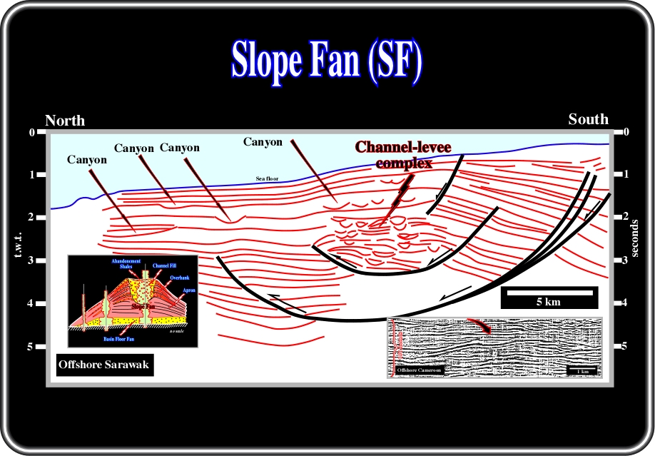
Fig. 51 - On this quick interpretation of a seismic line of offshore Malaysia, a thick slope fan was deposited in association with a listric fault (normal updip, reverse downdip). Indeed, channel levee complexes are easily recognized by the typical "gull wing" morphology induced by the overbank deposits, in which opposite downlap relationships are readily distinguished. In the lower right corner, a detail of a seismic line of the Cameroon conventional offshore in which the geometry of a channel levee complex is illustrated.
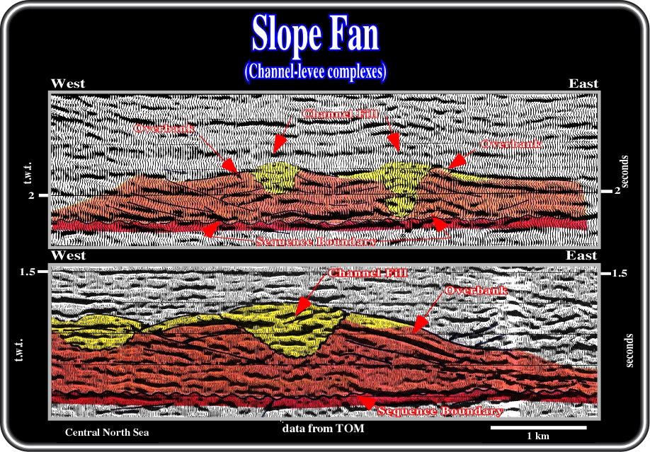
Fig. 52- In the upper close-up are illustrated the main reservoir interval of a major oil field in the North Sea, in which slope fan sandstone reservoirs are paramount. Admittedly, in this kind of seismic data, it is quite evident that the knowledge of the different depositional models precedes the interpretation (“Theory Precedes Observation”). In other words, in this particular example, if the seismic interpreter does not know, a priori, the different depositional models of the lowstand systems tract, he can not understand the migration / entrapment petroleum subsystem, and so, the petroleum system itself. On the contrary, if he knows, and understands, the depositional systems of the lowstand systems tract, he can propose a tentative interpretation as illustrated. Indeed, knowing a priori the depositional model of the slope fan member of a lowstand systems tract, they can readily recognize, the reflections terminations, the seismic surfaces and the most likely location of the potential reservoirs: (i) the lower sequence boundary, which corresponds updip to an unconformity, can be easily picked, (ii) the opposite dowlap of the levees become evident, as well as (iii) the channel fills, i.e., the filling of the central conduits, which were the pathway of the turbiditic currents. So, taking into account this interpretation, one can say the main reservoirs of the field are the sandstones filling the original depression between the overbanks of a slope fan (this context, the term channel can be misleading). On this subject, it is crucial to notice the mounded morphology of the top of the infill, which when explained by differential compaction implies a sand facies. In the lower close-up, again, the a priori knowledge of the depositional systems composing the lowstand tract is a sine qua non condition to perform a coherent tentative interpretation . Young explorationists should not think that an increasing seismic quality, or 3D data, can replace geological knowledge. Actually, it is the opposite, i.e., an increasing in quality and definition of the data requires a higher geological knowledge of the seismic interpreter. If not it is like giving a Ferrari to a guy who does not know how to drive a car. Briefly speaking, knowing the depositional models, taught in all Geological Schools, and the regional context of the area, the lower close-up can be easily interpreted as depicted.
(iii) Lowstand prograding wedge (LPW)
As eustatic sea level passes the lowstand position and beguins to rise slowly, this effect, combined with continued basin subsidence, beguins to move the relative position of the sea upward toward the old shel-slope break. Rivers deposit shelf sediments beyond the old shelf break and bay, delta and shoreface sands begin to accumulate on the upper topographic slope as relative sea level rises. These units prograda laterally into the basin, resulting in deposits in bathyal to abyssal water depths composed predominantly of shales with a few thin turbidite sands.
If the prograding complex receives a large volume of sand supply, this system may become overloaded and any minor short-term lowstand results in a basin floor turbidite sand at the shingled toe of the prograding complex.
A thick series of shallow marine deltaic and shoreface sands may stack vertically in the updip portion of the prograding complex. Subsequently differential compaction may result in a closed compaction high over these sands. Because the shelfward lateral seal is poor, these shallow marine sediments generally require structural closure to trap hydrocarbons.
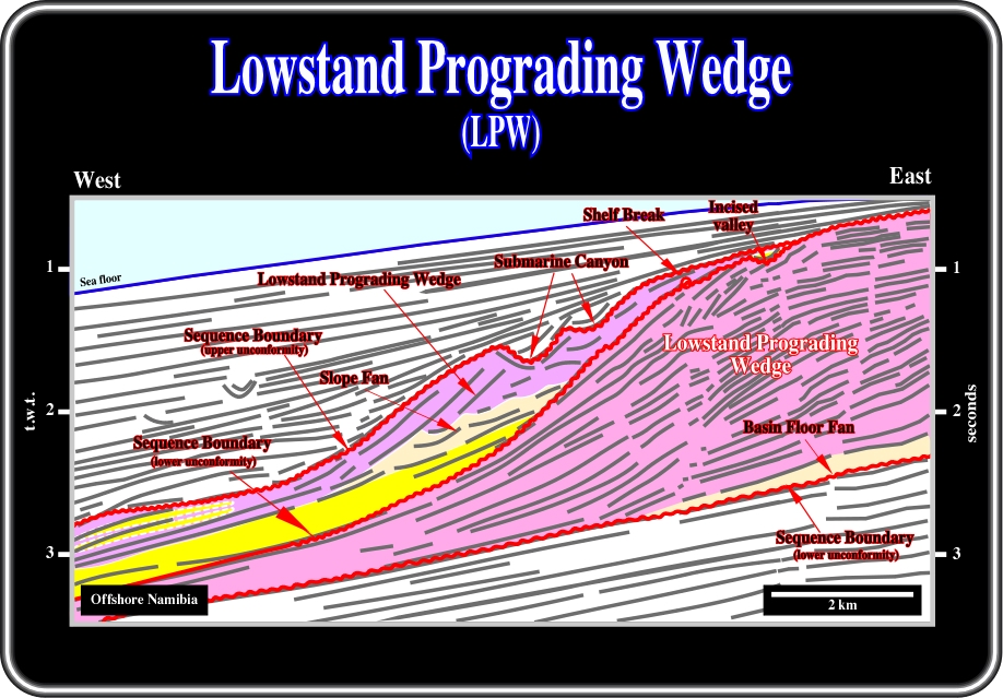
Fig. 53- In Namibia deep offshore, as illustrated on this tentative interpretation, lowstand prograding wedges (PLW) are paramount. Two incomplete sequence-cycles are individualized by sequence boundaries easily recognized by onlap and toplap (truncation) seismic surfaces and associated incised valleys. Lowstand prograding wedges are not necessary formed by deep-water sediments. Indeed, shallow water depositional systems, such as deltas, for instance, are often present landward of the shelf breaks. Seaward progradation gives the overall forestepping geometry of lowstand prograding wedge (LPW). In the upper sequence-cycle, the lowstand prograding wedge (LPW) fossilizes, progressively, the slope fan (SF) and the basin floor fan (BFF). On the other hand, shingled turbidites were deposited at the toe of the distal progradation. In the lower sequence-cycle, which is also incomplete, the lowstand prograding wedge fossilizes the lower sequence-cycle boundary and the distal part of a slope fan.
Prograding complex sediments typically infill any associated submarine canyons cut into the old shelf margin during the late stages of the prograding complex time. These sediments also infill in the shelf, the river valleys.
At the end of prograding complex time, eustatic sea level begins to rise rapidly and a major flooding event occurs, starting the transgressive systems tract. Sand at the top of the prograding complex and on the adjacent shelf is reworked by this marine invasion, which is typically followed by deposition of marine transgressive shales, which provide a topseal for all lowstand system tract units.
In electrical logs, lowstand prograding wedges are characterized a positive log-sequence, that is to say, by a coarsening and tickening upward log interval, as illustrated on fig. 54.
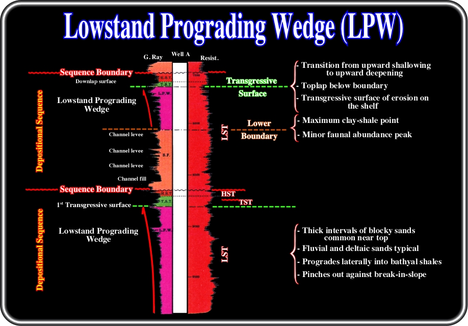
Fig. 54- The log patterns associated with a lowstand prograding wedge (LPW,) is depicted here. Roughly speaking, one can say that they emphasize a coarsening and thickening stratigraphic interval. In other words, in sand-shale facies, the sand layers are thicker and coarsening toward the top of the lowstand prograding wedge. In terms of relative sea level, one can say that the sand layers are thicker and coarser as the sea level rises in acceleration. The top of the lowstand wedge is defined by a flooding surface produced when the rate of sea level rise reaches its maximum.
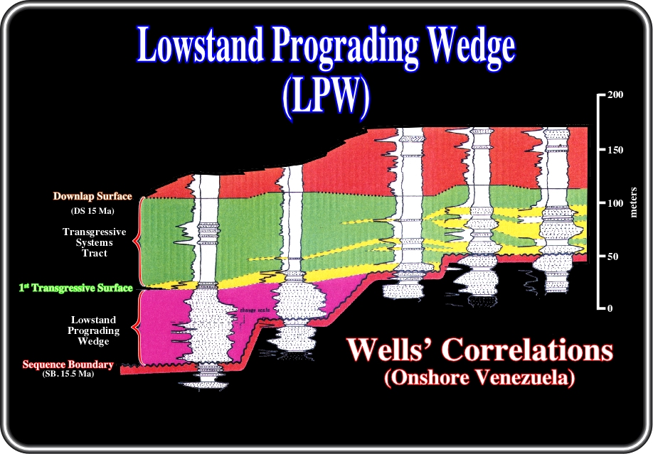
Fig. 55- This figure illustrates the sequential stratigraphic correlation between five wells located in an onshore basin of Venezuela. The 15.5 Ma sequence-cycle boundary is easily recognized in the majority of the wells. In seismic lines it corresponds to a quite evident onlap seismic surface and in the electrical logs, as depicted above, to the limit between a coarsening and thickening interval and a thinning and fining upward interval. Two wells penetrated the lowstand prograding wedge (LPW) seaward of the 15.5 Ma shelf break. The lowstand prograding wedge is overlain by a transgressive systems tract (TST), which landward of the 15.5 Ma shelf break overlies directly the 15.5 Ma sequence-cycle boundary. In other words, landward of the 15.5 Ma shelf break there is no lowstand prograding wedge. In hydrocarbon exploration terms, the sandstone horizons of the lowstand prograding edge are hydrocarbon bearing as well as the landward thickening transgressive sandstones. These correlations strongly suggest the oil trap is fundamentally non-structural, probably stratigraphic. Such a conjecture is not refuted, i.e., the seismic lines crossing the field corroborate it.
The exploration applications of lowstand prograding wedges were summarized by Vail (1989) as follows:
1) Rservoir
- Variable. Stacked fluvial, deltaic and shoreface.
- Variable continuity2) Migration
- Probably depends on fault conduits from deeper source.
- Possible downward migration from transgressive systems tract (TST).3) Source
- Deeper beds or transfressive systems tract (TST) source at top.
4) Traps
- Typically structural.
- Possible compaction closure.5) Seal
- Good transgressive systems tract (TST) seal.
- Lateral seal may be poor.
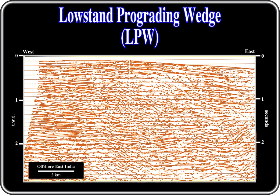
Fig. 56- On this sketch of a seismic line from offshore East India, a major unconformity and a lowstand prograding wedge (LPW) is easily recognized by its forestepping geometry overlying a thick slope fan (SF). The "gull wing" geometry, with its opposite downlaps and the seaward displacement of the successive lowstand shelf breaks of the lowstand prograding wedge (LPW) are evident enough for a tentative solution to be proposed.
A. 3) Turbidite deposits associated with LST
As depicted in fig. 57, the turbidite deposits associated with the lowstand systems tract (LST) can occur in all of the three member:
A.3.1) Lowstand Prograding Wedge (LPW)
- Shingled Turbidites
A.3.2) Slope Fan (SF)
- Canyon Fill or Slump Blocks
- Overbank Deposits
- Distal Overbank Mudstones
- Channel Sands
- Basin Floor Thin Bedded TurbiditesA.3.3) Basin Floor Fans (BFF)
- Sheet Lobe facies
- Unamalgamated Turbidites
- Amalgamated Turbidites
- Channelized Facies
- Contourites
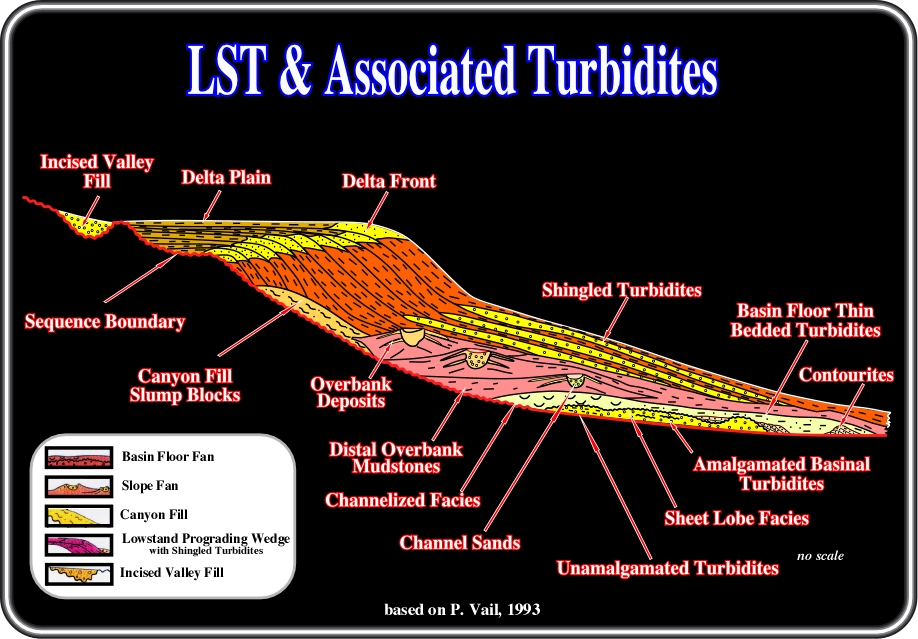
Fig. 57- Several types of turbiditic deposits are associated with lowstand systems tracts. In the lower member, i.e., in a basin floor systems tract, the following turbidite depositional systems can be found: (i) amalgamated basinal turbidites, (ii) unamalgamated turbidites, (iii) Sheet lobe facies, (iv) Channelized facies, (v) Basin floor thin bedded turbidites and (vi) Contourites. In the slope fan systems tract, one can find: (i) Overbank deposits, (ii) Distal overbank mudstones and (iii) Channel sands with associated (iv) Canyon fills and slump blocks. In the lowstand prograding wedge systems tract, shingled turbidites are often found at the toe of the progradations.
Similarly, the logs patterns associated with the turbidite deposits of a lowstand systems tract are quite characteristics and can be depicted as illustrated in fig. 58.
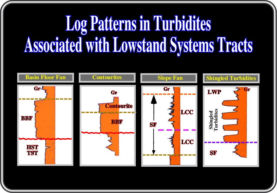
Fig. 58 - On this sketch the more likely log patterns associated with the lowstand turbidite depositional systems are summarized. The log pattern of the basin floor fan has a general cylindrical morphology with quite abrupt upper and lower limits. The log pattern of contourites is similar to that of the basin floor fan, but the internal parallel configuration is generally dipping seaward or concordant with the sense of the bottom seafloor current. The log pattern of a slope fan, as said previously, is characterized by a stacking of increasing and decreasing thickness patterns with interbedded channelized patterns. The log pattern of the shingled turbidite is characterized by a stacking of cylindrical boxy shaped sandstones separated by significant shaly intervals (see fig. 59).
to continue press
next
![]()