
Universidade Fernando Pessoa
Porto, Portugal
Turbidite Systems
in
Hydrocarbon Exploration
B.3.2- Sinuous Turbidite Channels
Isolated sinuous turbidite channels are usually identified by their characteristic pattern on amplitude slices of volumes of 3D seismic. In some cases, they are reasonably well imaged on 2D surveys, where one single line can image the same channel several times due to the sinous nature of the channel.
Thick sinuous complexes appear to develop when slope equilibrium is re-established in an area previously starved and oversteepened by tectonic activity during the period of starvation, or oversteepened simply as a result of hemipelagite deposition during a period of starvation (oversteepening does not imply a precise angle, it corresponds to the contrast between the actual slope and the equilibrium slope of the system at issue).
We use here the term “sinuous channel” for turbidite systems in order to avoid confusion with meandering fluvial channels. Sinuous channels develop in turbidite environments, when the density of turbidity currents is just slightly higher than the density of seawater, i.e. the currents carry a very small amount of sand. Sinuous channel fills are often shaly. Meandering (fluvial) channels typically develop in low-grade fluvial plains and high amounts of sand are deposited as point bars in the inner bends of the channels while the outer bank is excavated. Notice that in classic sedimentology, a flow is sinuous when the ratio of sinuosity, (distance between two points following the flow versus the shortest distance between them), ranges between 1.5 and 2 and is meander-form when it is higher than 2.
Seismic amplitude responses sometimes suggest that some sinuous (turbidite) channels can be filled by sand. These would result from more complex histories, where the sand infill is not associated with the process that built the meanders, but by the passive infill in a later stage of meanders created during episodes of low activity.
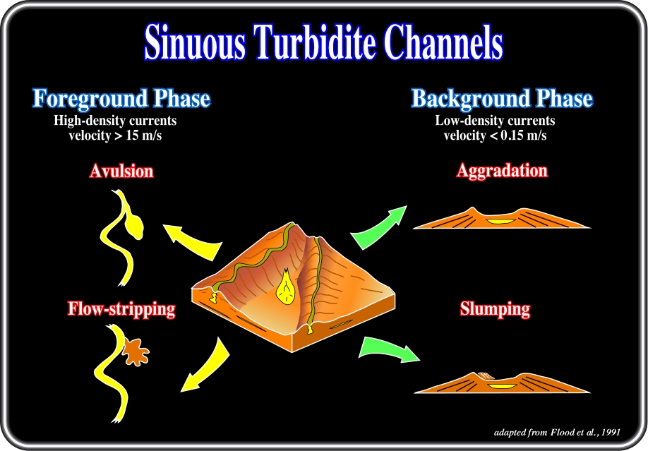
Fig. 71- The avulsion mechanism, that is to say, a sudden cutting off or separation of land by an abrupt change in the course of the stream, in turbidite systems has been treated by Flood et al. 1991. Avulsion typically leads to a steepening in slope, with the new channel less sinuous than the old abandoned one. As the new channel progressively re-establishes equilibrium, its sinuosity increases to reach a maximum after which it essentially aggrades vertically.
Such complexes typically show the growth of a single channel over several hundreds of ms (t.w.t.). The channel over that period of time usually shows a progressive increase from lower to higher sinuosity. Most of the time, a maximum sinuosity is reached after a while and pure aggradation occurs afterwards with progressive migration downslope (sweep).
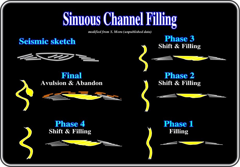
Fig. 72- Contrary to fluvial meanders, which essentially get filled by progressive lateral accretion, turbidite sinuous channels typically get filled by successive episodes of cut and fill. Downcutting is interpreted to result from higher energy flows and produces sinuous lows, which are further filled up by retrogradational packages of turbidites. Like in fluvial meanders however, successive episodes of cut and fill migrate laterally towards the concave bank due to the curvature of the channel. Hence the similarity in the final geometry at seismic scale.
The main differences between fluvial and turbidite sinuous channels result from the difference in accommodation (fig. 72). Accommodation in fluvial systems is usually low, its rate of creation corresponding roughly to the subsidence of the area. On the other hand, accommodation in turbidite systems is best defined as the difference between the actual profile of the system and the “equilibrium profile” corresponding to the sediment supplied to the system (flow volume and sand / mud ratio). In many cases, accommodation for turbidite systems is very high, allowing for high aggradation, whereas fluvial systems essentially migrate laterally. In other terms, the ratio between lateral migration and aggradation is high to very high in fluvial systems, and low in turbidite systems.
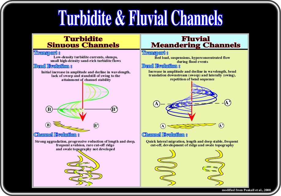
Fig. 73- Sinuous turbidite channels are created by low-density currents, slumps or small high-density sand-rich turbidite flows. The bend evolution is characterized by an increase in amplitude and decline of wavelength with a lack of sweep and standstill of swing to attainment of channel stability. The channel evolution is characterized by strong aggradation, progressive reduction of length and depth, frequent avulsion, rare cut-off ridges and absence of swale topography. Fluvial meandering channels are created by bed load, suspensions and hyperconcentrated flow during flood events. Their bend evolution is characterized by an increase in amplitude and decline in wavelength, bend translation downstream (sweep) and laterally (swing) with repetition of bend sequence. The channel evolution is marked by a quick lateral migration, length and depth stability, frequent cut-offs, and development of ridge and swale topography.
Equilibrium profile is probably the main quantitative difference between fluvial and turbiditic “meander belts”. For comparison, the equilibrium slope of meandering rivers is in on the order of 1:10,000, that of turbidite “meanders” more commonly ranges between 1:100 (Rhone) and 1:1000 (Indus) (see Clark and Pickering, 1996, for a compete review).
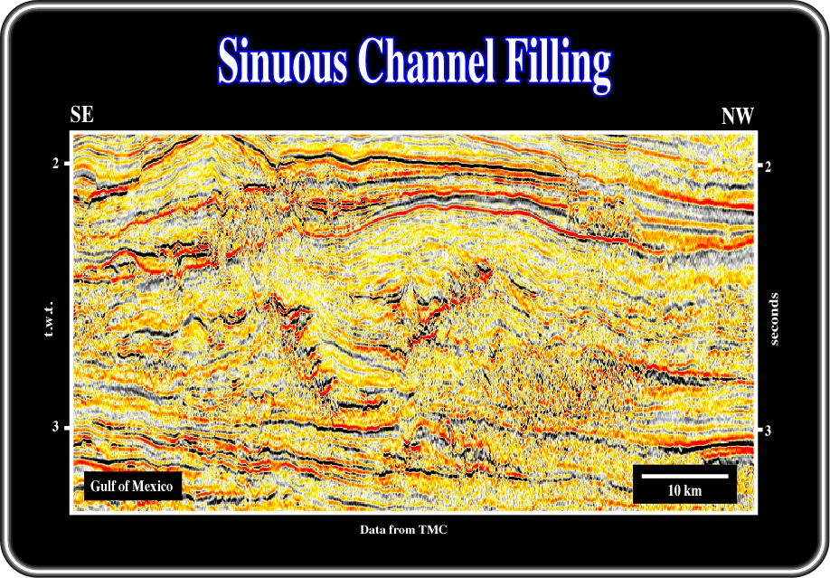
Fig. 74- Two well-expressed channel-levee complexes in the deep Gulf of Mexico are shown above. The lower channel displays very clearly a succession of downcutting events followed by rather aggradational dominated fill. Both channels can easily be mapped, and are clearly highly sinuous in map view. Note that the migration is unidirectional for each channel complex, indicating that the lateral component of migration is predominant with respect to the downstream component.
The reservoirs of small turbidite systems include small lobes deposited at the termination of rectilinear channels, the proximal part of levees (proximal in relation to the channel with which they are associated), and the infill of channels, either rectilinear or meandering. As recognized in the Baudroie-Baliste small turbidite system (Gabon offshore), where from bottom to top three main patterns were distinguished in channel complexes: (A) terminal lobes associated with rectilinear channels, (B) rectilinear channel fills and (C) Sinuous Channels (fig. 68). A similar patterns occurs in the northern offshore of Angola (75).
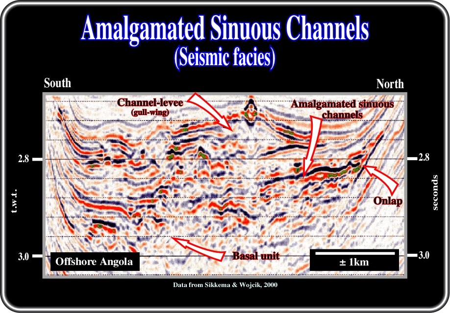
Fig. 75- Shell explorationists recognized similar turbidite facies within channel complexes of small turbidite systems first distinguished by Elf geologists in offshore Gabon. Indeed, as illustrated on this close-up of a seismic line from deep water Angola (South Congo Basin), from bottom to top of the channel-complex, the following facies can be recognized: (i) a low-reflectivity chaotic facies dominated by sandy debrite deposits, (ii) high-reflectivity chaotic and semi-continuous facies with sinuous channels (in time slices, see fig. 76) dominated by amalgamated channel sands and (iii) gull-wing channel-levee at the top of the channel complex. The basal unit is dominated by clean, very poorly sorted debrite sands, eventually with muddy debris flow deposits. These sandy debris flow deposits seem to be distributed as elongate lobes within the initial channel incision as suggested by certain time slices (fig. 77).
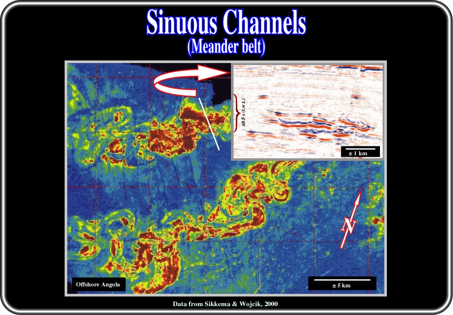
Fig. 76- In this figure (for confidential reasons the scales and locations of the seismic line are quite approximate) the geometries of meander belt channel complexes are easily recognized. The northern complex, which is characterized by meanders with less sinuosity, contain basal debrite sand deposits, which seem to correspond to elongate lobes within the initial channel incision, as illustrated in fig. 77.
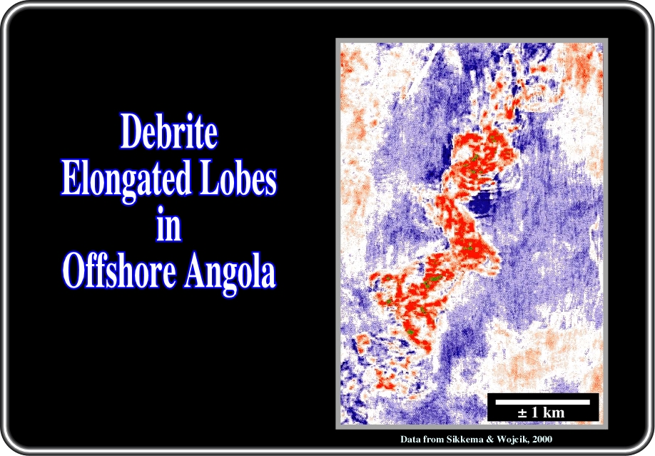
Fig. 77- On this horizon time slice done at the base of an Oligocene channel complex from the northern offshore of Angola, a seismic pattern characterizing debrite-dominated elongated lobes filling the initial incision channel are illustrated.
Taking into account lateral migration, width-depth ratio, sinuosity, vertical aggradation and the rate of sand accumulation, Clark and Pickering (1996) proposed several potential channel complex patterns as illustrated in fig. 78.
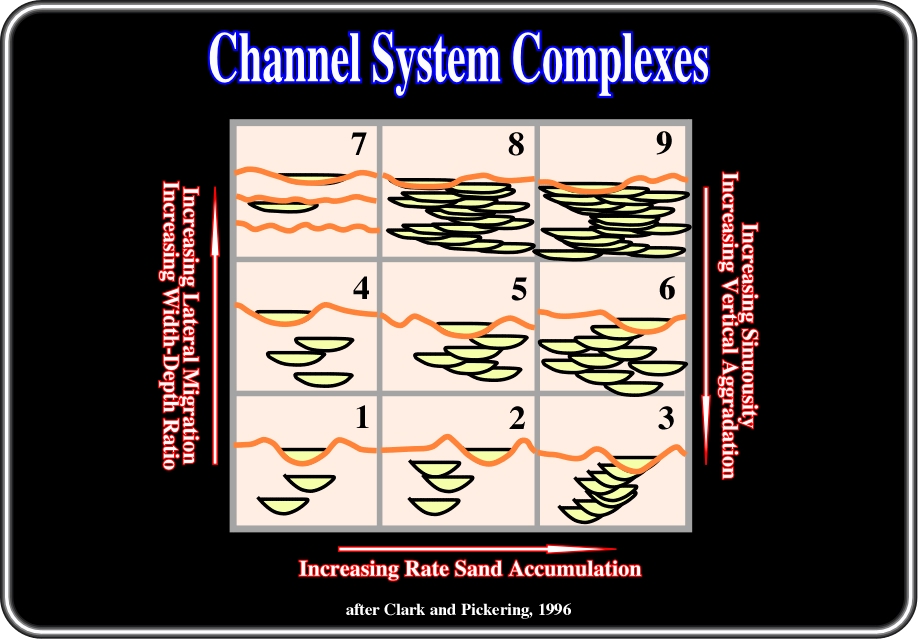
Fig. 78- When in a submarine channel system, lateral migration and width-depth ratio are strong, sinuosity and vertical aggradation are low and rate of sand accumulation is high, the more likely pattern of the system, on the ground or in seismic lines, looks like the one depicted in sktech 9.
to continue press
next
![]()