
Porto, Portugal
Contents:
5.1- Basement Involved
      5.1.1- Compression (1 horizontal)
              5.1.1.1- Folds & Thrusts
                          A- Folds
                          B- Reverse Faults
                          C- Thrust Belts
            5.1.1.2- Compressive Strike-Slip
                        A- Small horizontal displacement (1-5 km)
                        B- Medium horizontal displacement (5-20 km)
                        C- Large horizontal displacement (20 km)
5.1.1- Compression (![]() l horizontal)
l horizontal)
When a sedimentary interval is shortened by folding, the fold axes are usually oriented perpendicular to the maximum regional stress (
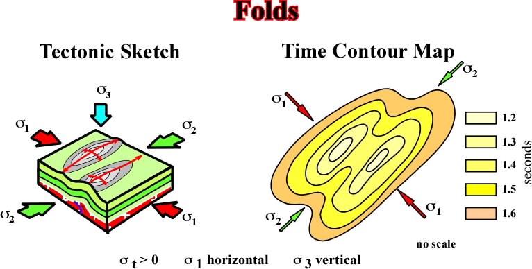
Fig. 119- Cylindrical folds are the structures created when a sedimentary basin is affected by a compressional tectonic regime with a
As the Jura Mountains' folds are considered as a prototype, let's make a quick review of the different mechanisms which have been invoked to explain their origin. Ihese mechanisms have been appealed for general folding:
(i) Uplift mechanism........................... (ii)Lateral shortening mechanism.
Nowadays, the large majority of geologists follow the last theory, in which different variants are possible:
a) The stress is conveyed by the sedimentary overburden (i.e., passive basement).
b) The infrastructure or basement conveys the stress.
The volume problems created by folding in the center of the anticlines have been resolved in different ways by geologists to take into account the 2nd Law of Thermodynamic (Goguel's Law):
1) Folding of basement. ..............................2) Thrusts of basement.
3) Crushing of basement. .............................4) Flowing of mobile layers.
5) Disharmony folding in the earth of the anticlines.
The Chiru Anticline (Iran) shows small strike-slips faults, which cut the anticline axis at different angles.
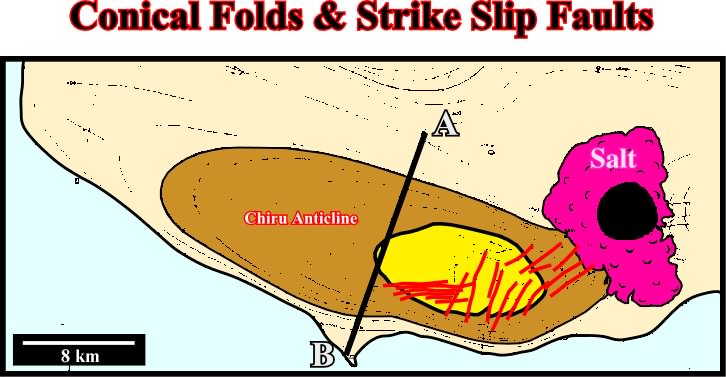
Fig. 120- The geological map of the Chiru anticline strongly suggests the axis of the anticline, i.e. the
These kind of faulting was recognized by Wegmann in the Jura mountains:
- The strike of beds and the strike of the bent axes of the different anticline compartments, do not correspond to the strike of the macro-anticline itself.
- The local axes are rotated. This rotation corresponds to a longitudinal lengthening typical of a lot of folds.
- The beds when bent, developed slickensides on the bedding surfaces, and not in planes perpendicular to the tectonic stress. That means, that the symmetric planes suggested by quick interpretations, do not correspond to realistic interpretations.
- The geometry of the different structural elements of some anticlines gives a triclinic and polar symmetry.
The seismic line AB, illustrated in fig. 121, is located in fig. 120. It cuts the Chiru anticline perpendicularly to the axis, i.e. roughly parallel to
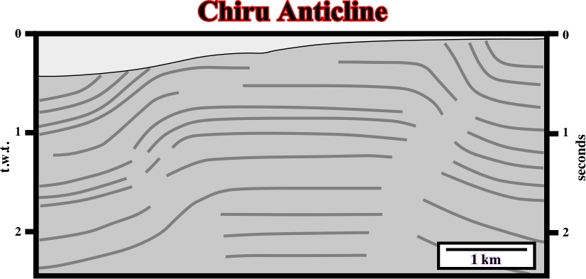
Fig. 122- On this seismic line, it is quite evident the sediments were shortened, and so uplifted by a compressional tectonic regime with s1 roughly parallel to the trace of the profile. The folding (concentric) was not sufficient enough to accommodate the sediments since reverse faults on the flanks of the anticline are easily recognized particularly on the right flank. On the contrary, the small strike slip faults allowing the lengthening of the anticline along the
Another way to shorten sediments is by resverse faults as illustrated below:
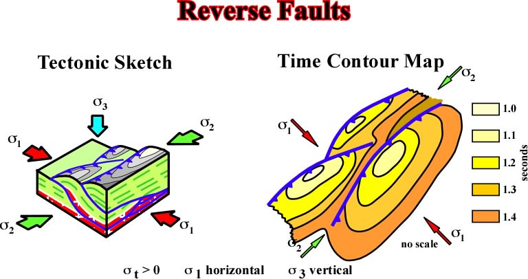
Fig. 123- Reverse faults develop during compressional tectonic regimes with
Seismic example of a reverse fault:
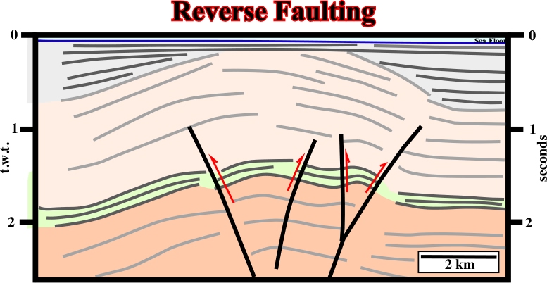
Fig. 124- On this line, the uplift of the sediments underlies a shortening created by a compressional tectonic regime with a
Three remarks must be kept in mind when interpreting reverse or thrust faults on seismic lines:
- A reverse fault is a shortening of the sediments as an answer to a regional compression.
- An anticline is often developed in the hangingwall to favor shortening.
- The axis of the anticline is more or less parallel to the strike of the reverse fault.
When two faulted blocks are recognized on a seismic line and the shortening is mainly localized in the hangingwall (upthrown block), the fault is reverse, i.e. the fault plane dips toward hangingwall as illustrated in fig. 125.
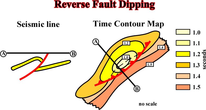
Fig. 125- This sketch is quite important and can avoid seismic interpreter to make mistakes. Indeed, when two fault blocks are evident on a seismic line, righthander interpreters (without tectonic knowledge) have a natural tendency to pick normal faults, i.e. faults with a fault plane dipping toward the dowthrown block. However, this sketch that them than when the shortening is located in the upthrown block, the fault is reverse since the fault plane dips toward the hangingwall.
Seismic example:
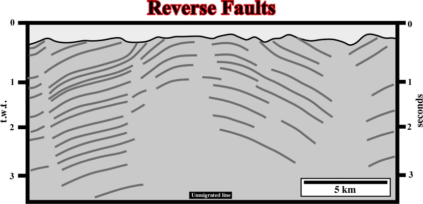
Fig. 126- On this seismic line, roughly paralle the
On the other hand, note that:
- A rollover structure, often located in downthrown fault blocks) is an extensional structure. It is associated with a lengthening and not with a shortening.
- A compaction structure, even when located in an upthrown fault blocks should nver be taken as a shortening structure.
- The vergence or overthrow direction is the direction of overturning or of inclination of a fold, or a fault.
The term vergence was coined by Stille (vergenz in Germany), to indicate the direction in which a geologic structure or family of structures is facing. In an isotropic homogeneous flat region subjected to compression, it is not possible to predict the vergence of folds of faults. Two main factors determine the vergence of a fault:
i) The topography (gravity).
ii) Pre-existing faults or weak zones, i.e. feactures already present in the substratum.
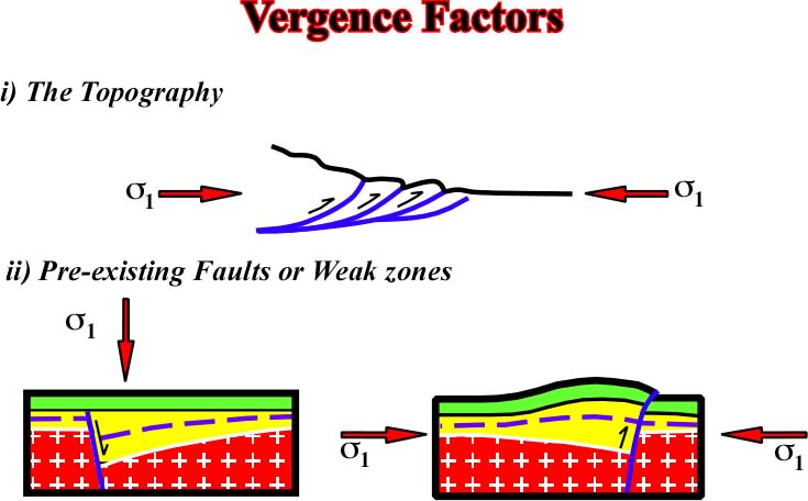
Fig. 127- Topographic anomalies and heterogeneities of the substratum, often, control the vergence of faulting (normal and reverse). In the upper sketch, it is quite obvious the vergence of the reverse faults is controlled by the orientation of
Seismic examples:
i) Vergence related to topography:
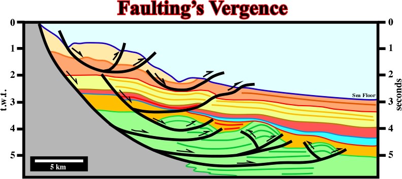
Fig. 128- The vergence of these listric faults is controlled by the water depth and associated confining pressure. In spite of the fact that, in the upper part of the fault planes, the movement is normal (extension), in the lower part (seaward), the movement is reverse. Indeed, in the toe of the fault planes, the sediments are shortened (local compressional tectonic regime) to counterpart the updip extension. Similar large scale examples are found in divergent margins with active shalokinesis or halokinesis.
ii) Vergence related to reactivation of pre-existing faults.
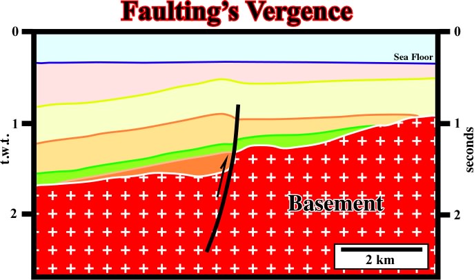
Fig. 129- In this example, a pre-existing normal fault, bounding a small rift-type basin, was reactivated during a later compressional tectonic regime. Taking into account the strike of the pre-existing fault and the strike of
In the last example, where the pre-existent fault controlling the vergence of the reverse fault was a normal fault developed during a rifting phase (basin type Rift), it is important to note the fault plane has a “null point”, i.e. a point with no apparent displacement:
(i) Above the “null point”, the fault has a reverse geometry.
(ii) Below the "null point", the geometry of the fault is normal, in spite of fact that the fault is reverse. Its last movement was reverse, but not enough to change the geometry.
A thrust belt can be defined as a reverse fault complex where faults dipping 45°, or less, over much of its extent and on which the hanging wall appears to have moved upward relatively to the footwall. However, a horizontal compression rather than a vertical displacement is at the origin of these geological structures.
- Tectonic ramp

Fig. 130- On this theoretical model, high pressure levels (detachment plane) and pre- faults or weak zones exiting (ramp) can control shortening in thrust belt areas.
- Fault spread diagram
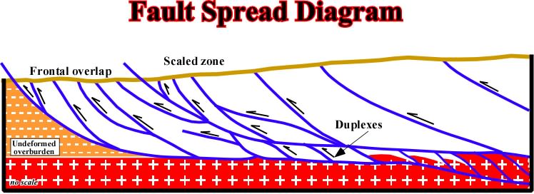
Fig. 131- In a thrust belt complex, faults planes are interconnected and related. Locally, duplexes structures are possible as illustrated above.
The following seismic examples illustrate thrust faults and tectonic ramps. Their geological interpretation is not too difficult when the interpreter takes into account some evident pitfalls.
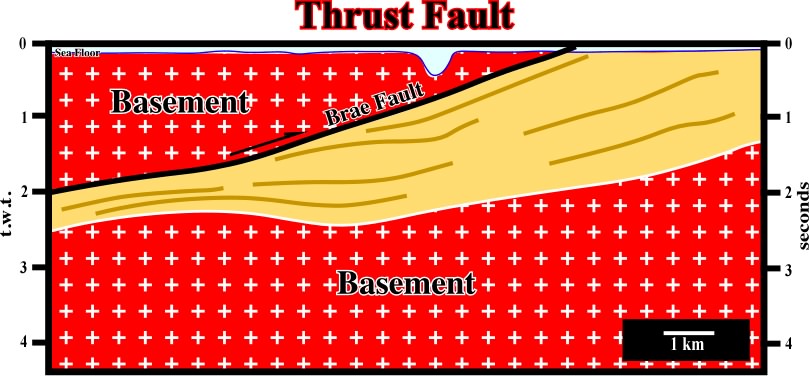
Fig. 132- A major thrust fault is recognized on this seismic line. Due to the geometry of a thrust fault, the hangingwall sediments are older than those of the footwall, and so, their density is higher, which gives, in time sections, a lateral change of velocity and the associated pitfall, i.e. a pull-up of the footwall sediment under the hangingwall. Subsequently, interpreters must be careful when a antiform structure is identified below a thrust fault plane in a time seismic line. Very often much of such structures are apparent and they no not exist in depth versions.
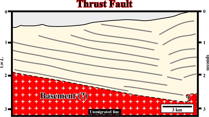
Fig. 133- On this line, one can find the geological principle allowing identification of reverse faults: (i) the faulted blocks (downthrown and upthrown) are easily recognized by the associated seismic surfaces, (ii) the shortening is located in the upthrown block, (iii) the fault planes dips toward the upthrown block, (iv) the downthrown blocks are slightly tilted with minimum of shortening, (v) the topography of the ground corroborates the reverse faulting interpretation, i.e. the maximum shortening is the upthrown block: shortening induces uplift.
A similar remarks can be made on the line illustrated on the fig. 134:
a) The faulted blocks are easily recognized.
b) The shortening is located in the upthrown side.
b) Two fault planes with opposite vergences, i.e. dipping in opposite directions.
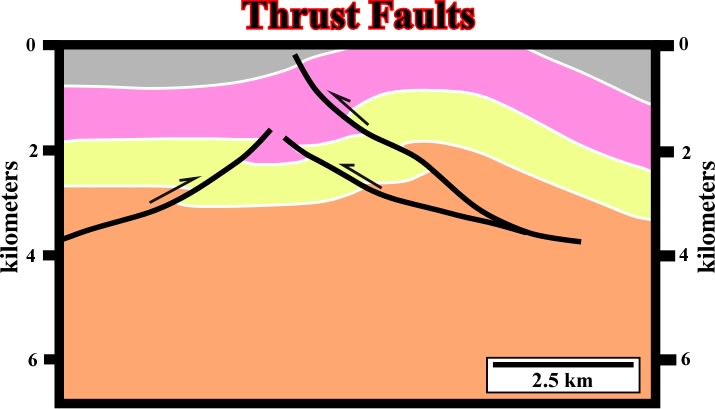
Fig. 134- In the geological interpretation of seismic lines, particularly those in a compressional setting, interpreter must take into account the Goguel's Law. Indeed, the above interpretation looks very coherent. The folding seems concentric, and the dips of the reverse faults are in agreement with the Anderson's Law (the seismic line is in depth and the scales are almost the same as in the field, i.e. 1:1). Nevertheless, In Science the truth doesn't exist. So all seismic interpretation must be tested in a critical approach (see fig. 135).
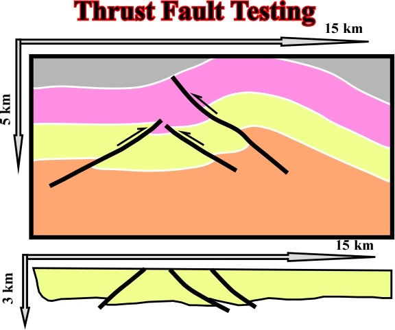
Fig.135- Testing the geological interpretation of the previous figure it is easily to recognized than it is easily falsified by the Goguel's Law. Indeed, volume's restorations using the software Locace indicates that the thickness of the yellow interval was not kept constant during deformation. A constant thickness of the yellow implies a quite different a different dip of the reverse fault planes.
Coherent seismic interpretations can only be obtain by a trial and error approach as strongly suggested by Sir K. Popper (1934).
5.1.2- Compressive Strike Slip
When the ellipsoid of effective stresses is characterized by a
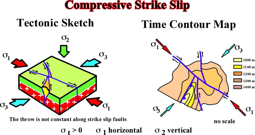
Fig.136- In a compressional tectonic regime, when the basement is involved and the
In field or seismic maps, it is very difficult to find strike-slip faults without associated folds. Indeed, under a regional compression, shortening can be made by:
a) Folding (cylindrial and conical)
b) Faulting (reverse or strike slip)
c) Reactivation of pre-existing faults.
The following figure illustrates the geological map of Pontarlier-Vallorbe / Lausanne area, where several kinds of faults can be developed, particularly strike-slip faults.
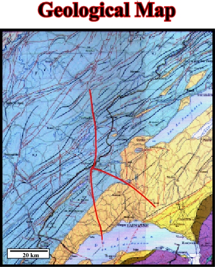
Fig. 137- On this geological map, one can recognize (i) the strike slip faults displaced the folds (the geometry in each fault block is the same, (ii) the strike slip faults are pre-folding (the geometry of each compartment is different), (iii) some of the strike slip faults have an "en-échelon" geometry, which implies a basement movement.
Wegmann summarized the Jura strike-slip faults, particularly the oblique strike slip faults, as follows: (a) they are visible on every topographical map, (2) they are important geographical features, (c) There are faults of different magnitude, (d) each variety plays a different role, (e) big strike-slip faults can cut several anticlines and synclines, (f) other cut only one anticline, (g) another category cuts only through a part of an anticline, (h) these last allow an anticline to change form, to be more or less inclined or to change direction, (i) t hey disappear often on marly horizons and (j) those, which cut only one anticline often, finish in a syncline and turn into small thrust faults.
In association with big strike-slip faults, the anticlines and synclines of opposite sides have largely different structures, such as those of Vallorbe - Pontarlier faulting zone, where one can note the folding has continued after the displacement on some of these faults. On the other hand, one can find evidence suggesting they were originally normal faults:
(i) They are indications of movements of the basement.
(ii) The folding is one expression of a more complicated structure.
(iii) The folding is superimposed on several older anisotropies.
(iv) Some of these anisotropies can be often seen in outcroppings.
(v) They are not only faults but also pre-existing faults.
(vi) The faults and the joints have very often controlled and directed the displacements.
The following figures illustrates a tectonic sketch of oil field in Iraq, where one can notice that folds (conical folds) are often associated with strike-slip faults.
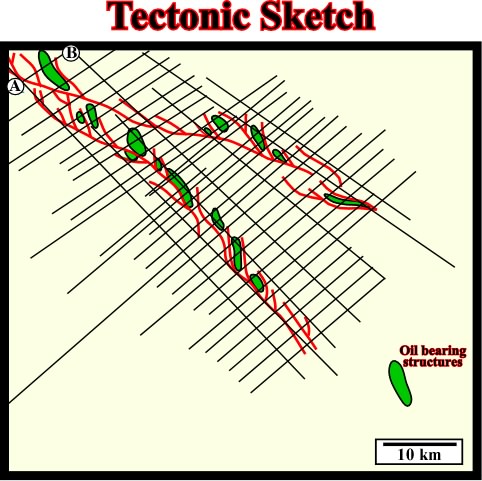
Fig. 138- This tectonic sketch, built-up with a relatively dense seismic grid, strongly suggests the oil bearing structures are, in fact, conical folds created by lateral displacements of basement blocks, which induce in the sedimentary cover complex strike slip faults. The cross section AB on the left upper corner of the tectonic sketch corresponds to a seismic line, which is illustrated on fig. 139.
These strike-slip faults are often the reactivation of previous normal faults, discontinuities or lateral changes of facies, as suggested by seismic line below:
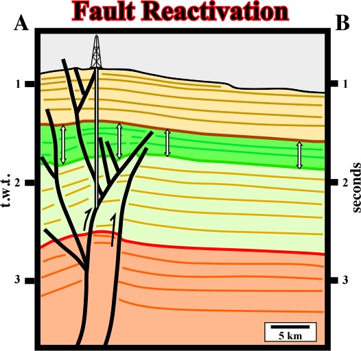
Fig. 139- On this seismic line, which is roughly perpendicular to s1 during the late compressional tectonic regime, it is quite evident that a pre-existing normal fault, recognized by the change in thickness in each side of the fault of the seismic interval bounded by the green and yellow reflectors, was reactivated as reverse fault. The shortening of the sediments is recognized by reverse faulting and folding (buckling). The folding is conical. Indeed, on parallel lines, the apex of the structures is progressively displaced toward or outward of the trace of the major reactivated fault.
Wegmann recognized the importance of the horizontal displacement undergone by the basement and proposed different mechanisms to explain how to shorten the overburden sediments without shortening the basement, and how the folds are developed.
The increasing (time and amount) of horizontal displacement in basement strike slip movement develops in the overburden a reorientation of the structures. A typical sequence of these structures is often as follows:
A) Small horizontal displacement (1-5 km);
"En-échelon" folds and faults.
B) Medium horizontal displacement (5-20 km);
"En-échelon" folds faulted by strike-slip faults rooted in the substratum strike-slip.
C) Large horizontal displacement (20 km)
Wrench faulted zones with uplift and erosion of previous structures.
The affected stripe (area of deformation) along the trace of substratum strike-slip becomes narrower and narrower as the deformation progresses, as illustrated below (fig. 140).
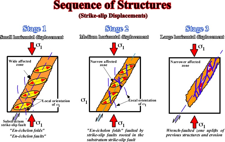
Fig. 140- As illustrated, the three major steps of deformation created in the sedimentary cover by an increasing strike-slip displacement of basement blocks are: (i) en-échellon folds, (ii) faulted en-échellon folds and (iii) wrench faults. As deformation progresses the area of deformation becomes narrower what implies a significant uplift (Goguel's law).
A- Small horizontal displacement (1-5 km)
The associated structures are mainly en-échellon folds: (fig. 141).
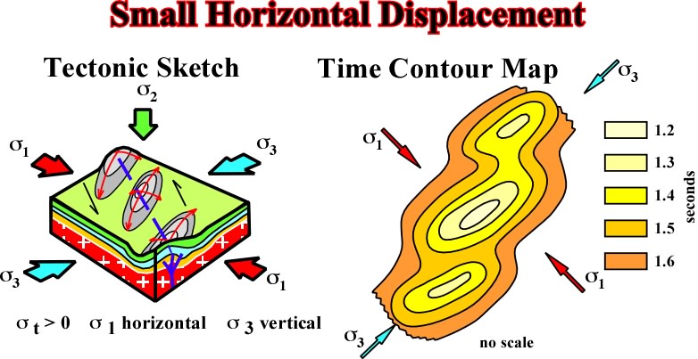
Fig. 141- En-échellon folds are conical folds. Indeed, When plotted in a stereographic projection, they do not lie in a great circle, as the cylindrical faults, but in a small circle (parallel) with horizontal or dipping axis.
The axis of the conical folds tends to become parallel to the fault. There is a reorientation of
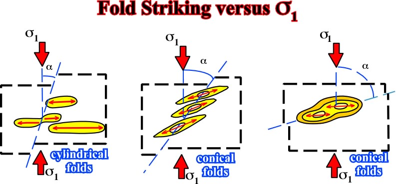
Fig. 142- The orientation and relationships between strike slip-faults and cylindrical and conical folds, can be summarized as following: (i) the vertical amplitude of the conical fold is often greater when
As folds associated with substratum strike slip movement are conical folds, the axis is not perpendicular to regional
B- Medium horizontal displacement (5-20 km)
In such hypothesis, the associated structures are "En-échellon" folds faulted (fig. 143).
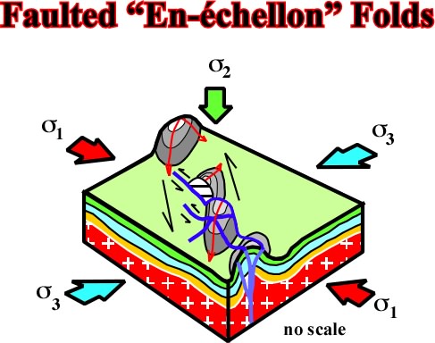
Fig. 143- In this particular example, as lateral displacement increases shortening cannot be done just by folding. The axes of anticlines are displace"d by strike slip faults. Subsequently, the plane of the strike-slip faults become essential for "up dip" closure. The associated traps are no more structural as in "en-échellon folds, but morphological by juxtaposition.
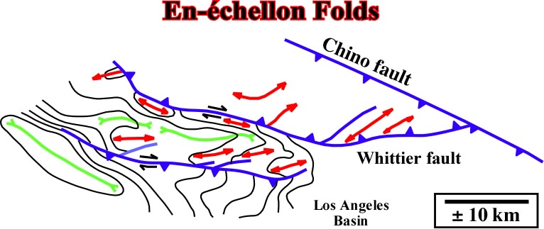
Fig. 144- In spite of the fact that some of the traps associated with the en-échellon folds in Los Angeles basin are morphological by juxtaposition, one cannot say that the majority of the structures correspond to faulted en-échellon structures. Indeed, as illustrated in this sketch the structures are typical en-échellon folds induce by the movement of the main strike slip faults.
The next seismic line illustrates a sedimentary shortening associated to with strike-slip movement affecting the basement in Sumatra. The strike-slip movement is around 10 km and the folds associated are conical structures.
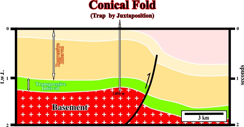
Fig. 145- This seismic line was initially picked in extension (1973), i.e. the fault plane individualizing the fault blocks was dipping toward the dowthrown block. However, since interpreter notice that the shortening, and uplift, was mainly in the upthrown block, immediately the structure was considered as compressional. Subsequently the fault was picked as reverse with the fault plane dipping toward the upthrown block as illustrated. In addition, the mapping of the fold located on the hangingwall showed that its geometry was conical, since axial direction is oblique to the strike of the fault.
The area illustrated on the map below (fig.146) was affected by intense strike slip movement. The lateral displacement is medium, i.e. the horizontal throw of the faults ranges between 10-15 kilometers. The faulting is synchronous or slightly posterior to the folding. The faults developed by this strike slip movements have sub-vertical fault planes. The associated potential traps for hydrocarbons are mainly morphological by juxtaposition traps, which some American geologists call erroneously "fault traps". The folds are mainly faulted "en-échellon" folds. Structural traps, i.e. four ways dips closures are rare.
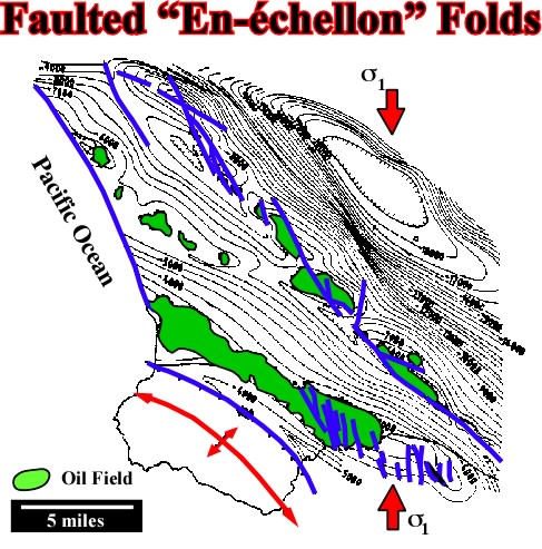
Fig. 146- On this map, the majority of the hydrocarbon traps are morphological by juxtaposition, i. the hydrocarbons are laterally trapped by sealing rocks that the movement of the faults planes put in juxtaposition with the potential reservoirs rocks. In spite of the fact that these traps are known by some as fault traps, it is important to say that a fault never traps, what traps is the rocks in the other side of the fault (in juxtaposition with the reservoir) or the rocks filling the gauge zone.
The relative chronology of faulting must always be predicted carefully in order to avoid erroneous interpretations, particularly when explorationists evaluate the timing of migration in relation to the age of trapping. Indeed, one of the key parameters of hydrocarbon exploration, when the presence of mature source-rocks is assured, is the age of the potential trap in relation to the migration of the generated hydrocarbons. A trap created after hydrocarbon migration has almost no chances to be filled by hydrocarbons, but if there a dimigration took place.
C- Large horizontal displacement (20 km)
When the displacement is large enough wrench faults are developed (fig. 147):
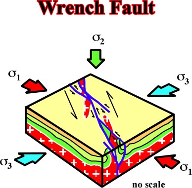
Fig. 147- "San Andreas fault" is one of the most studied examples of this kind of faults. Basement outcrops are well seen near the fault zone and the oil bearing basin is located at more than 50 km eastward, where "en-échelon folds" and faulted "en-échelon" are developed. The area of deformation became narrow and uplifted.
Another typical area of this kind of deformation is the western part of Sumatra island in Indonesia (148):
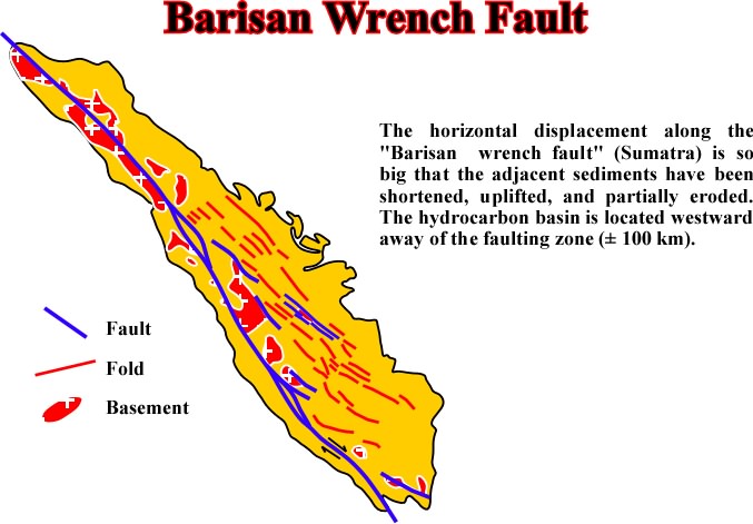
Fig. 148- In Barisan fault, the lateral displacement of the basement fault blocks is so big, that blocks of the basement were uplifted and form large outcrops all along the area of deformation. Westward of the major wrench fault the prospectivity of the sedimentary basin is not only due to the presence of excellent source rocks by the large number of traps associated with en-échellon folds.
One must remember that geological laws control all deformations. Thus, it can be said that during a shortening stage, the movement of:
(i) the newly appearing faults and,
(ii) the already existing faults, which became active again,
is determined by (A) their dip and (B) the angle that the pre-existing faults form with the s1, as illustrated in fig. 149:
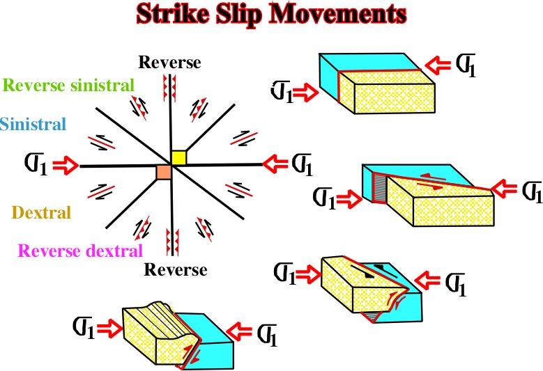
Fig. 149 - When sediments are deformed, in compression or in extension, all pre-existent structures are reactivated during new tectonic regimes. Assuming there are inheritated structures striking in all direction, their reactivation depends mainly of the angle between their strike and the new
Before ending this chapter we would like to insist that sediments are not necessarily isotropic and homogeneous: They are anisotropic and heterogeneous. So, under a regional compressional regime, the effective stresses can reactive old fracture zones individualizing different blocks within sediments are shortened independently. "Apparent" strike-slip faults are one of the reactivations which are very often misunderstanding. The following sketch (Fig.150) what should be understood by an "apparent strike slip fault":
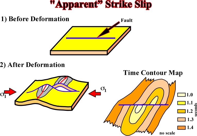
Fig. 150- The presence of a pre-existing fault zone or a weak zone can apparent displaced new formed structures. Indeed, in this particular example, both blocks of the pre-existent fault were deformed independently, creating two more or less parallel anticlines, but not to anticlines rejected, since the fault zone is pre- and not post-deformation. Such mechanism can explain several "strike slip faults" in onshore Venezuela, as the Urica or Anaco fault.
Similar results are obtained when a compressional tectonic regime follows an extensional regime:
a) During an extensional regime, with a s1 vertical, normal faults are developed parallel to
b) Later on, during a compressional regime (s1 horizontal), the fault planes of pre-existing normal faults will be reactivated creating “inverted structures” such as the one illustrated in fig. 151.
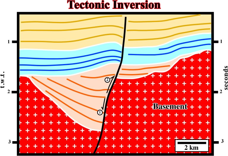
Fig. 151- On this seismic line, a tectonic inversion created by the reactivation of pre-existing extensional structures is quite evident. The pre-existing normal fault of the hal-graben rift-type basin, was later reactivated as reverse fault during a compressional tectonic regime. Taking into account that the tectonic inversion was not total, two geometries can be recognized along the fault plane: a normal geometry in the lower part and a reverse geometry in the upper part of the fault plane. These geometries are separated by a point where apparently there is no displacement- the null point.
c) The reactivation of pre-existent faults, or weak surfaces, obeys to two main geological laws. Before analysing the laws controlling the reactivation, we will summarize the implications of the presence of a null point in a fault plane.
A) Null Point (fig. 152)
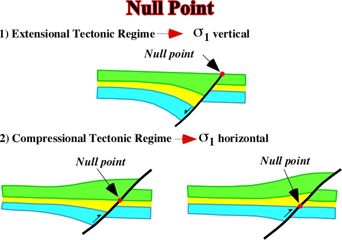
Fig. 152- Below the null point the geometry of the fault is that of a normal fault, while above, the geometry is that of a reverse fault. The position of the null point on the fault plane depends of the amplitude of the inversion. Higher is the null point smaller is the inversion. When the null point is on the bottom of the fault plane, the inversion was total, and so only the reverse geometry is recognized.
The marker that appears “unfaulted” on the fault plane is the Null point.
- In a normal fault, the null point is always located in the uppermost section of the fault plane.
- When a normal fault is reactivated in reverse, during the reactivation, i.e. during the reverse movement of the fault, the null point moves downward.
- The final fault is reverse fault (compressional tectonic regime).
However, as said previously:
1) Above the null poin, the reverse fault thas a reverse geometry.
2) Below the null point, the reverse fault has a normal geometry.
These geometries are clearly recognized on seismic lines (fig. 153), when a compressional tectonical regime was present in the area. Indeed, a compressional tectonic regime follows always an extensional regime. Indeed, the sediments before being deformed must be deposited and deposition takes place during extensional tectonic regimes.
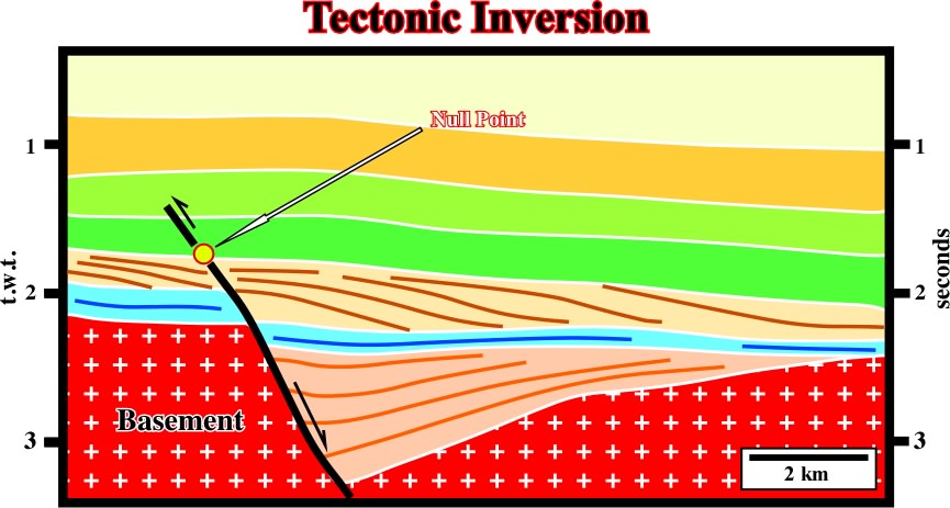
Fig. 153- On this North Sea line, the null point is located on the upper part of the fault plane: (i) It limits a normal geometry below it, where the sediments still seems lengthened, from a normal geometry, where the sediments are slightly folded, (ii) the tilted fault blocks developed during an extensional tectonic regime, are sealed by transgressive sediments which underlying a progradational interval, (iii) these intervals, which can be identified on the hangingwall and the footwall, allow stratigraphic correlations and the calculation of the fault displacement.
The reactivations on North Sea have been explained as a consequence of two mjor factors:
a) The Alpine's orogeny
During the Late Tertiarye, the Alpine's orogeny effective stresses were transmitted northward along the basement's laminations reactivating the pre-existent normal faults.
b) Ridges push
This hypothesis is corroborated by the analyse of focal mechanism of the eartquakes and certain deformation, which cannot be induced by conventional tectonic regimes. In fact, focal mechanisms in offshore Norway clearly indicates a reverse mechanism with a s1 striking N 110°.
B) Angle between s1 and the strike of the pre-existent fault
As said previously (see fig. 149), the reactivation of normal faults by compressional tectonic regimes is function of the angle between the
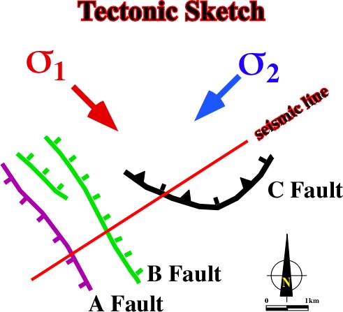
Fig. 155- On this tectonic sketch there are three faults belonging to quite different tectonic regimes. They have different direction, Subsequently, when the area will be affected by a new compressional tectonic regime, they will be reactivated in different ways as corroborated by the seismic line illustrated in fig. 155.
In the previous tectonic sketch, one can predict:
- The normal faults A and B, strike in a parallel direction to
- The fault C striking almost perpendicularly to
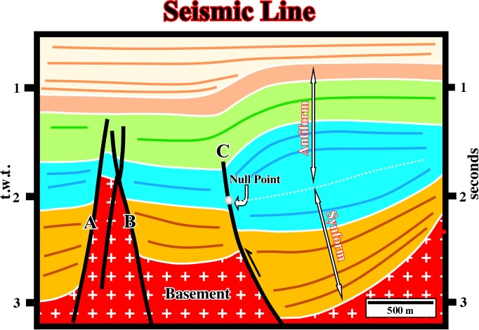
Fig. 156- This seismic line corroborates the fact that only the fault C, which strikes roughly perpendicularly to the new
C) Angle between s1 and the dip of the pre-existent fault
The reactivation of a normal fault by a compressional tectonic regime is, firstly, a function of the: angle between
1) Planar Faults
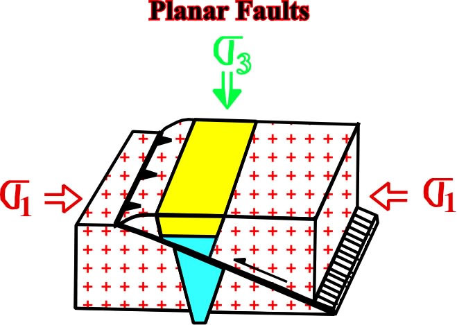
Fig. 157- The pre-existing grabens bounded by normal faults dipping 60° and striking perpendicularly to
2) Non-Planar faults

Fig. 158- In non-planar normal faults, the deepest part, with a dip of 45° or less, is far from the optimum conditions for reactivation. Contrariwise, the shallow part having a high angle can not easily be reactivated and inversion, by buckling and folding, occurs above the fault plane. Consequently, as illustrated, two opposite geometries can be recognized. In the lower part a synforme geometry and in the upper part an antiforme geometry.
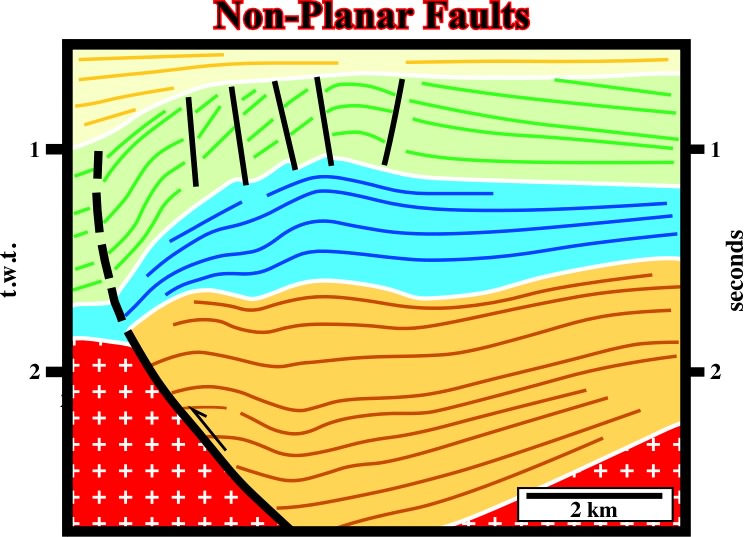
Fig. 159- One can say the lower part of this non-planar faults was reactivated by inversion, i.e. the sediments were shortened by a reverse movement of the pre-existing normal faults, whereas as in the upper level, the sedimentswere shortened by folding. Consequently, in the upper sediments, i.e. those shortened by folding, it is normal to find small strike slip faults near the apexes of the anticlines. These strike slip faults allow the lengthening of the sediments along
On seismic lines, the small strike-slip faults on the topo of anticlines are often erroneously interpreted as normal faults associated with an younger extensional tectonic regime (what can happen). Their apparent normal geometry is easily refuted by the cartography. Their mapping shows (i) they are limited to the apexes of the anticlines, (ii) they arIn conclusion, they are not associated with a regional extensional tectonic regime, they length the anticline's axes, so they are associated with compressional regimes.
As illustrated in the block diagram (fig. 158), the seismic line on the fig. 159 is a non-planar normal fault developed during an extensional tectonic regime is, under a compressional regime. It is reactivated in the lower part of the fault plane, where the dip is around 45° or less, as a reverse fault, while the upper partof the fault plane inversion was by buckling and folding.
The reactivation of pre-existing normal faults is extremely frequent in the sedimentary basins associated with the formation of megasutures. Back-arc basins, associated with the Meso-Cenozoic megasuture, are rich in inverted structures which are excellent hydrocarbon traps. These traps are structural and with favorable hydrodynamic factor as illustrated below (fig.160).
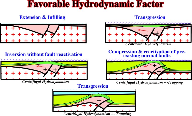
Fig. 160- During extensional tectonic regimes, the hydrodynamism is centripetal. However, as tectonic inversions took place, the high structural points become low points and the low structural points become high points, and so, centrifugal hydrodynamism becomes preponderant. Subsequently, hydrodynamism being down dip enhances the possibility of non-structural trapping, particularly the stratigraphic traps associated with the transgress if intervals, as illustrated on the next seismic line (fig. 161).
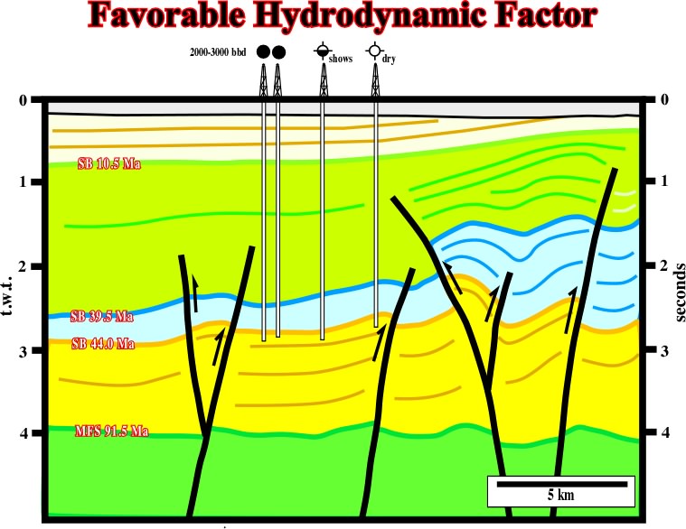
Fig. 161- The location of the wells with hydrocarbons corroborates the hypothesis that the accumulations are associated with non-structural traps (stratigraphic) in which the trapping is enhanced by a strong down-dip hydrodynamic factor.
to continue press
next
![]()
Send E-mail to ccramez@compuserve.com or cramez@ufp.pt with questions and comments about these notes.
Copyright © 2001 CCramez
Last update: March, 2006