
Porto, Portugal
Contents:
5.2- Basement not involved (cont.)
       5.2.2- Shaly mobile substratum
                A) Compressional structures
                B) Extensional structures
                    B.1- Plasticity
                    B.2- Undercompaction
                    B.3- Fault displacement
                    B. 4- Fault associated with shale tectonics
                    B.5- Growth fault displacements
                    B. 6- Growth faults and traps
5.2- Basement not involved (cont.)
5.2.2. - Shaly mobile substratum
As for deformations associated with an evaporitic mobile substratum, deformations associated with sedimentary sequences above a shaly substratum can also be expressed in terms of lengthening (extension) and shortening (compression).
Detached compressional structures, i.e. anticlines and reverses faults or thrusts above a mobile shaly substratum, can be associated with regional or local tectonic regimes (fig. 270).
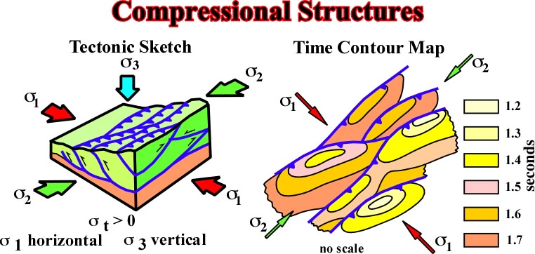
Fig. 270- Above the detachment plane (top of the mobile substratum), the compressional structures follow the conventional tectonic rulers. When
3 is vertical, anticlines and reverse fault strike parallel to
Reverse faults have been recognized in deep offshore of Nigeria and in the Mississippi deep sea fan in association with shalokinesis, in which gravity plays an important role (fig. 271). Similarly, they have been recognized in the trenches of convergent margins and accretionary prism (fig. 272), Here, are also shale tectonics plays an important role in spite of the fact that shortening is mainly created by a regional compressional tectonic regime.
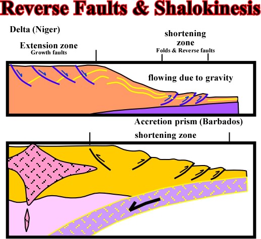
Fig. 272- Reverse faults in association with local or regional tectonic regimes are well know in deep offshore Nigeria and in accretionary prisms of convergent margins as for instance in deep offshore Barbados.
Notice that generally the bottom of a mobile substratum is very difficult to recognize. However, when it can be seen, contrariwise to the bottom of a evaporitic layer, a negative velocity anomaly (pull-down) is present in association with the tectonic dysharmony, i.e. the detachment or décollement surface.
B) Extensional StructuresLengthening can be associated with a tectonic stress positive (st >0) with shale ridges are partially developed parallel to the regional s3 and local stresses in the apex of the ridges create stretch faults parallel to the ridges (fig. 273).
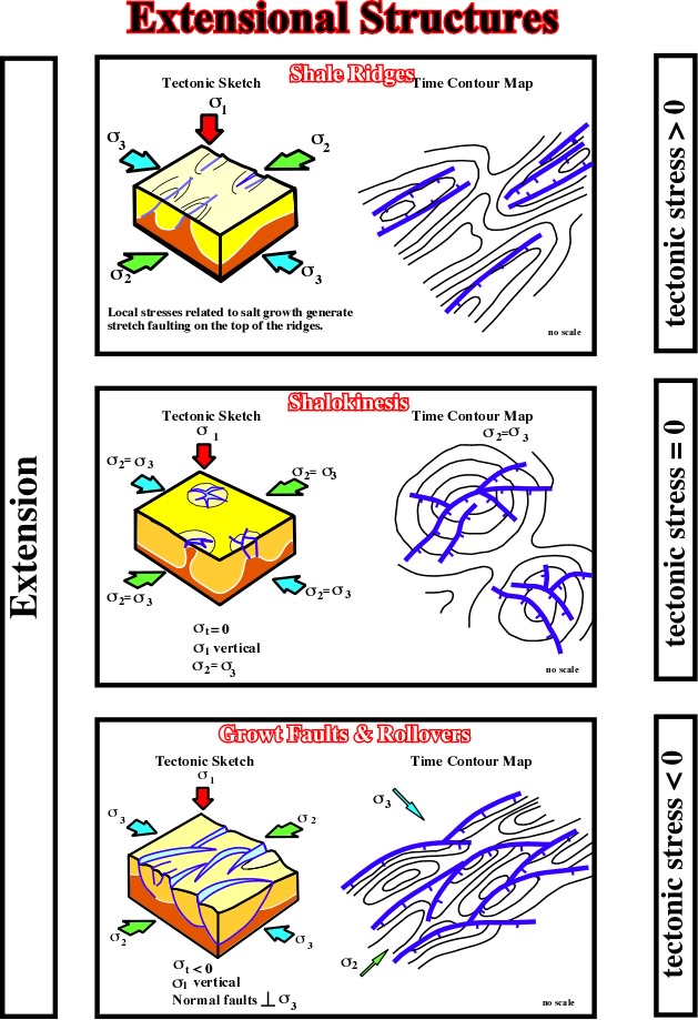
Fig. 273- Besides the local en equilibrium tectonic regime, created on the top of shale diapir, that is to say in absence of a tectonic stress, the extensional structures associated with mobile shaly substratum are mainly composed by normal faults (lengthening) striking parallel to
With a negative tectonic stress (
With a tectonic stress nil, i.e. in absence of a major tectonic stage, shalokinese can be very important. It usually it is synchronous of sedimentation and it can control, as the halokinesis, the facies and the thickness of the sedimentary sequences.
As shalokinesis (
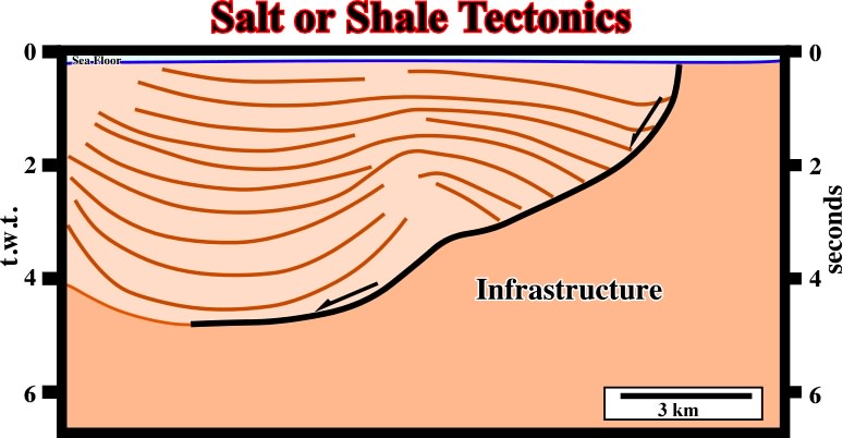
Fig. 274- Without regional context and in isolation, very often it is quite difficult to decide if a detachment plane is associated with a salt or shale interval. This is particularly true when the bottom of the mobile substratum is not well individualized. This seismic line shows a typical association between shale and salt movements.
In addition, these two types of tectonics are very often together (Gulf Coast Basin), and it is not always easy to differentiate salt domes from shale domes. On seismic lines, particularly at the bottom of mobile substratum, pull-ups and pull-downs can be difficult to recognize.
The chiefly principles of shale tectonics can be summarized as follows:
The plasticity of shales is mainly due to "undercompaction. Undercompaction can be the result of: (i) rate of deposition, (ii) burial, (iii) thickness, (iv) absence of evacuation drainage, etc.
Undercompaction produces:
a) a lowering of the density: a 30-40 % decrease compared with the density of normally compacted shale.
b) a geostatic disequilibrium which results in a vertical and lateral movement of the undercompacted shale.
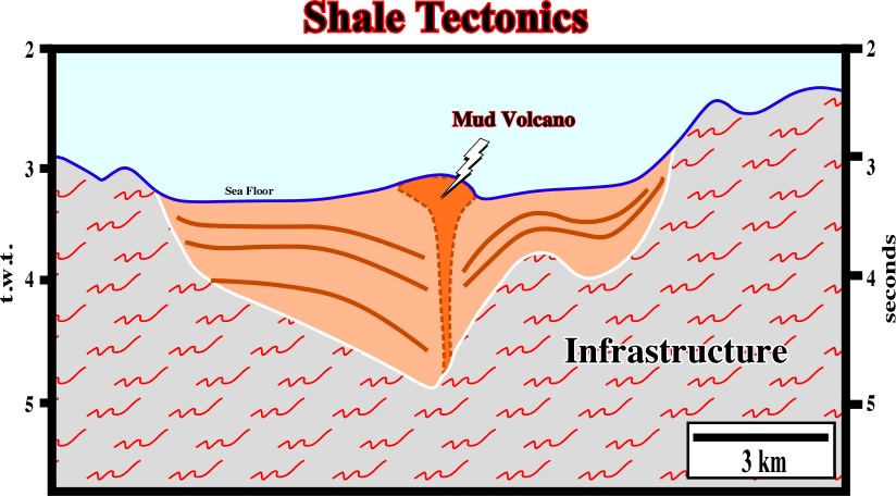
Fig. 275- On deep water of several divergent continental margins and Mediterranean basins shale tectonic, with its characteristics growth faults, mounds and diapirs, are paramount.
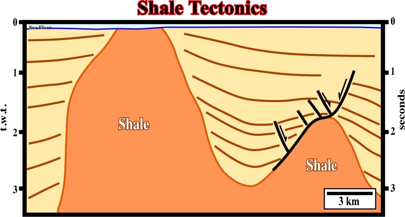
Fig. 276- Two well-known areas, the Niger delta and the Gulf of Mexico, can be considered as typical shale tectonic areas. On this line from Niger delta, shale diapirs are more than evident.
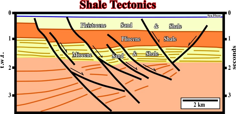
Fig. 277- On this seismic line, it is easily to recognize that the majority of the faults are pre-compaction. Indeed, the dip of those fault planes chances with the compactability of the intervals. i.e., plus compactable is the sedimentary interval lower is the dip of the fault plane.
The previous seismic line (fig. 277), shot in the Gulf of Mexico, shows the relationship between the growth faults and the shalokinesis: (i) growth faults, (ii) stretch faults, (iii) rollovers. These structures are particularly developed in areas where deltaic sand-bodies prograde over a mobile shale substratum as illustrated in fig 278.
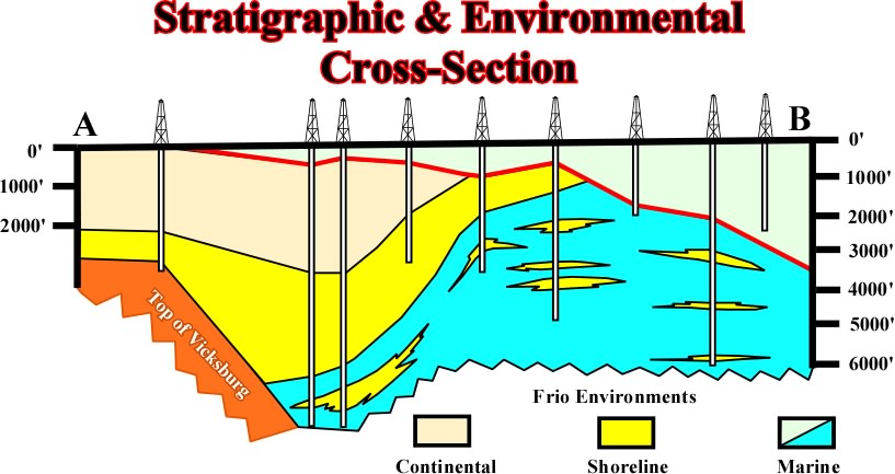
Fig. 288- This cross-section (onshore of Texas) through Agua Dulce #1, Indian Point #1, Corpus Christs ORPUS #1, Laguna Larga #1, Chevron #1, Sprint and S. Sprint #1, Carril #1, Superior #1, and Shell wells, shows: (i) the Anahuac transgression, (ii) the seaward displacement of the sedimentary environments: continental, shoreline, marine, particularly that of the Frio formation, (iii) the same upward displacement of the sedimentary environments is visible in the wells. In the same way, the electrical log of Indian Point field, illustrated on fig. 289, is very illustrative.

Fig. 289 - On this log it is easy to recognize: (i) an upward marine environment sequence with thin turbidite reservoirs, (ii) a shallow water environment with coastal sand reservoirs and (iii) continental environment with fluvial reservoirs. The significant hydrocarbons occurrences are within the environments with a sand/shale ratio ranging between 15 and 25% (that cannot be recognized just only this electric log), also, you can believe us but there are not hydrocarbons in the fluvial sandstones.
A geological interpretation of a seismic line seaward of the cross-section of fig. 288, is illustrated below (fig. 290).
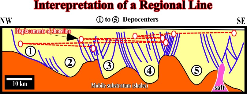
Fig. 290- On this interpretation (seismic line seaward of the cross-section illustrated on fig. 288, onshore Texas, one can recognize: (i) the displacements of the shorelines creating a regional regression, (ii) small transgressions intercalated during in the regional regression, (iii) outbuilding and upbuilding of geometry of the sedimentary intervals suggested by the different positions of the depositional coastal break (roughly the coastline during regressive episodes).
On the other hand, fig. 290 depicts the seaward evolution of the shale structures, i.e. (a) growth faults (without shale in the upthrown block), (b) growth faults with residual shale in upthrown block, (c) asymmetrical shale domes with a growth fault seaward and (d) symmetrical shale dome with stretch faults on top of the dome, but without growth fault. Such an evolution shows shale tectonics (shalokinesis) evolves in time and space.
The seaward progradation of sedimentary environments and development of growth faults, associated to shale tectonics, can be translated by "Aggradate ut progradamus" that is to say upbuilding is required to outbuilding. Let's see what that means when a deltaic interval prograding over a mobile shaly substratum (fig. 291).
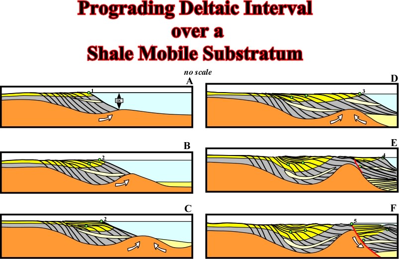
Fig. 291- The different steps, or stages, recognized on seismic lines when a deltaic interval progrades over a mobil substratum are depicted in this sketch (see text).
The evolution in time and space can be summarized as follows:
(i) During the stage A, in which the thickness of deltaic platform is between 20-150 m, the shoreline (depositional coastal break) progrades over the shale substratum, the the slope (continental or deltaic) is stable.
(ii) The shoreline and continental sands prograde seaward, at the same time that proximal turbidites and slope shales are deposited.
(iii) This mechanism creates a sedimentary depocenter which increases locally the vertical stress
(iv) As
(v) The first consequence of the mound developing is the increasing of the slope angle, which becomes unstable to a certain depth water deposition, critical depth (HC).
(vi) At that time, the sediments can not prograde because the slope is unstable, that is, it does not allow deposition.
(vii) Thus, more the substratum flows upward, more thick is the onshore depocenter and, as the slope is unstable, the sediments arriving to the shoreline are transported basinward by turbiditic currents, being deposited when the currents decelerate.
(viii) The result is a turbiditic upbuilding package deposited under a great water depth water. During this time (stage B), the shoreline (2) does not change.
(ix) The turbiditic upbuilding package, deposited in the bottom of the slope induces a new shale flowing which decreases the slope angle. Actually, at this stage of the tectonic evolution, the main event is the reduction of the angle of slope which becomes stable.
(x) When the slope angle is stable, the progradation of shoreline and deposition of continental sands and slope shales is possible (stage C): "Aggradate ut Progradamus".
(xi) The consequence of this seaward progradation is the displacement of the shoreline from 2 to 3, and thickening of the onshore (stage D).
(xii) As the evolution continues at a certain time, two big sedimentary depocenters will be developed landward and seaward of the shale dome.
(xiii) The pressure against the shale dome increases more and more, and the flanks of the shale dome become steeper.
(xiv) The seaward flank of the dome (due to the orientation of the tectonic stress
(xv) The exaggeration of this instability creates a typical gliding plane along the flank of the shale dome and a growth fault is developed with a thickening of the sediments against the fault plane and a slight transgression displaces the shoreline landward (5). It is the stage F.
Three remarks must be made:
- A shale mobile substratum implies a high pore pressure. The water pressure reduces the effect of the normal stress on the gliding plane and so reduces the frictional resistance gliding.
- This mechanism requires a strong terrigeneous influx, and it is the reason why this kind of structures are frequently associated with river dominated deltas.
- Proximal turbidites (fig. 292) are developed by the same mechanism, just the scale and the upbuilding change.
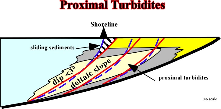
Fig. 293- When the deltaic slope is higher than 3º (the stability of a slope depends of the water depth), the delta front sandstones can glide seaward deposition in the toe of the deltaic slope (which in particular cases can correspond to the continental slope) what petroleum geologist (particular Shell's geologist) call proximal turbidites. Admittedly, such a deposition decreases the angle of slope what eventually can allow again s seaward progradation of the delta.
Very often geologist need to assess the fault displacement of the normal faults associate or not with shale tectonics. Such a displacement can be evaluated by different ways as depicted in fig. 293.

Fig. 293- Different ways geologists have to evaluated normal fault displacement.
We must add the stratigraphic throw, that is to say, the total thickness of missing section and the "cut-out", i.e. the missing section in an electrical log. When a well is vertical and the beds horizontal, then olne can say the throw = stratigraphic throw = "cut-out".
B. 4- Fault associated with shale tectonics
There are main to classes:
(a) stretch faults and
(b) growth faults.
The stretch faults, as in salt tectonics, are normally associated to the apex of the shale domes. The growth faults are associated to the flanks of the domes more than to the top of the domes. Growth faults are distinguished from other normal faults by comparingthe thickness of stratigraphic units in the upthrown and downthrown blocks and the fact that there can be no growth fault outside of an area of sedimentation. Thus, in a genetic, rather than a descriptive definition, a growth fault is simply a fault that offsets an active surface of deposition.
B.5- Growth fault displacements
A basic principle of faulting and particularly growth faulting is that the amount of displacement measured along the fault plane decreases from a maximum to zero in all directions. In other words, a fault lose displacement. The upper part of a growth fault system with bed thickening is the part usually considered as growth fault. The lower part of a growth fault system may show some of the accepted characteristics of growth faults, such as dip of the beds in the downthrown block back into the fault, but all movement is post-depositional or late in respect to the faulted beds.
The displacement of any expanded stratigraphic unit is the sum of
(1) contemporaneous displacement, and(2) late displacement,
as illustrated in figs. 294 and 295.
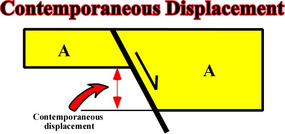
Fig. 294- Here, it is quite evident that the total displacement corresponds to the contemporaneous displacement, i.e. the expanded stratigraphic section.
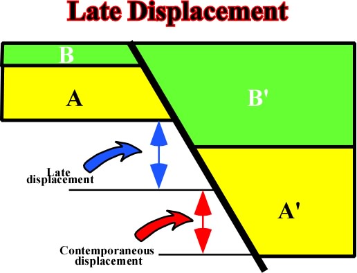
Fig. 295- Here the total displacement is the sum of the contemporaneous displacement (difference between A and A') plus the late displacement (in relation to A-A' movement), i.e. the thickness different between B an B".
In a growth fault, two sections can be recognized:
a) The pre-growth and pre-kinematic section. The offsetting began after the deposition of the lowermost bed.
b) The growth section exhibits both contemporaneous movement and post-depositional movement on all beds but the upper one.
The displacement of a growth fault expands a stratigraphic unit, so the hangingwall is thicker than the footwall. The movement of the fault creates more "room" (accommodation or space available for sedimentation) for deposition in downthrown side, as illustrated in fig. 296.
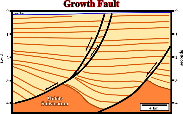
Fig. 296- When a fault is active during deposition, it means that the downthrown block, rotates, and the fault plane becomes less and less steep with depth, due to a volume problem.
The best single reason for the importance of growth fault structures in petroleum geology is the contemporaneous deposition and faulting. Indeed, the continuation of the system forms a structural trap almost immediately (fig. 297). Regardless of when the oil forms or migrates, an early formed trap is there to catch it. Growth faults also may increase and even improve reservoirs in downthrown block, particularly limestone reservoirs.
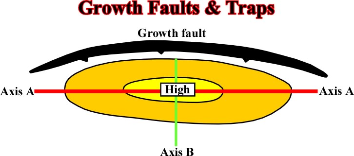
Fig. 297- In a growth fault there are two different closures: (i) parallel to the fault strike (Axis A) and (ii) perpendicular to the fault strike (Axis B).
(i) Closure parallel to the strike of the fault
The strike closure can be induced by:
1) The inital curved (concave upward) fault plane. Indeed, the vertical displacement changes laterally, being maximal, generally, in the central part of the fault.
2) Posterior deformation of the initial fault plane.
The word plane in fault plane conveys the idea that a plane exists. In reality the plane is the "nothing" between two surfaces formed at the time of dislocation. Seismically speaking, generally a fault plane is not emphasized by a reflector. It is characterized by a seismic surface defined by reflections terminations, as illustrated in fig. 296. Growth faults are particularly susceptible to two post faulting deformation: (a) compaction (fig. 297) and (b) late deformation, which implies a rotation of one of the blocks (fig. 298)
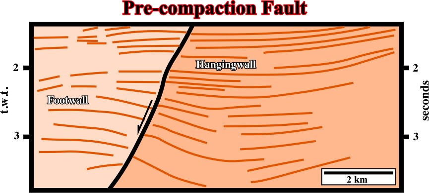
Fig. 297- The dip of a pre-compaction fault changes with the lithology. Higher is the dip of the fault less compactable is the juxtaposed sedimentary interval on the footwall (upthrown block).
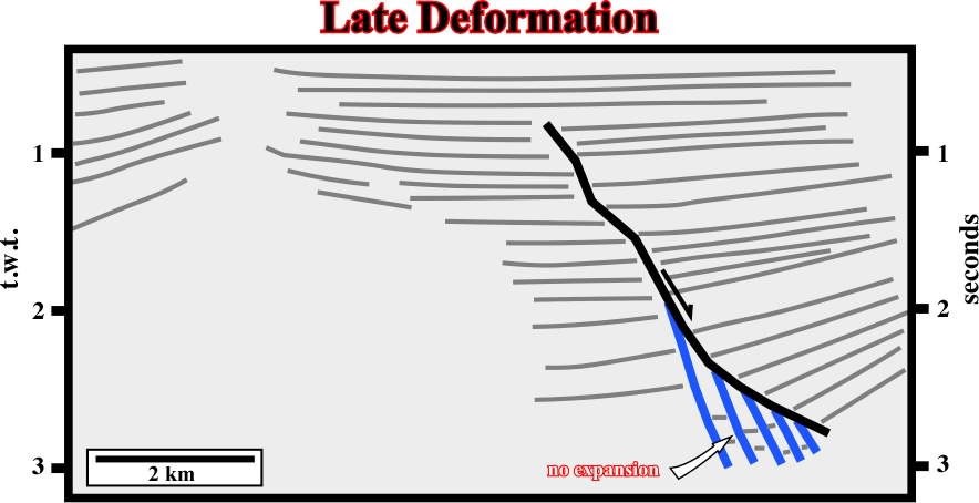
Fig. 298- On this line, the fault in red is precompaction as suggested by the changes in the dip of the fault with the lithology. On contrary, the faults in blue are posterior. They do not correspond to really normal extensional faults, but to plane discontinuities between rotated blocks (splintering or "horsetail" of the fault).
(ii) Closure perpendicular to the fault strike.
The continuous and post-depositional movement along a fault plane produces a "rollover" closure due to the "potential void ". All planes of growth faults have less dip at depth than at the surface. Therefore, a concave-upward geometry is developed and the its mapping of shows a spoon geometry rather than a rectilinear geometry. Another particularity of growth faults, as well as of all normal faults, is the impossibity of determine the tectonic "cut-out" in wells by lack of reference (fig. 299).
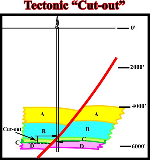
Fig. 299- As depicted, it is impossible with the well results to determine the cut-out. However, a combination of seismic and subsurface data can correctly approach the intercal not recognized in the normal faults.
press here
next
![]()
Send E-mail to ccramez@compuserve.com or cramez@ufp.pt with questions and comments about these notes.
Copyright © 2001 CCramez
Last update: March, 2006