Universidade Fernando Pessoa
Porto, Portugal

Salt Tectonics Short Course
12-Salt Expulsion Basins
In the previous chapter, we have mentioned several times salt expulsions basins. This kind of sedimentary basins, which are often called “mini basins”, is developed over allochthonous salt. Since the salt of an allochthonous salt nappe flows down-slope, it creates a local subsidence (compensatory subsidence). This subsidence combined with eustacy creates space available for sedimentation, that is to say, accommodation. Young and generally under-compacted sediments then fill the space available. These basins are easily recognized on seismic lines (fig. 313), time slices (fig. 314) and, under certain conditions, on bathymetric maps (fig. 315).
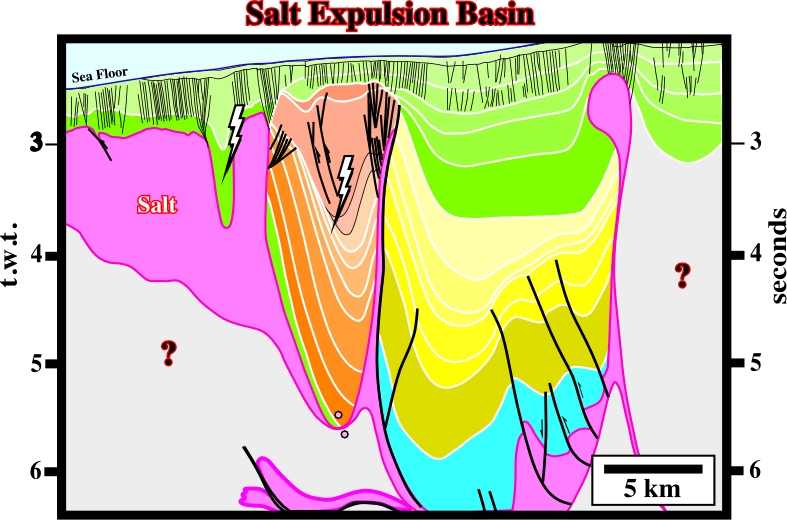
Fig. 313- In association with the allochthonous salt, which is connected with the autochthonous layer by a salt ramp, a large and a small salt expulsion basins are quite evident. The compensatory subsidence, which created them, can only by explained by salt flowage. The bottom of the small basin is clearly the allochthonous salt. A salt weld can occur at the bottom of the large basin, what means that hydrocarbons can eventually migrate into such a mini-basin. Chronostratigraphic correlations between seismic intervals within and outside of mini-basins are quite difficult in absence of calibration wells.
The salt expulsion basins are generally rich in reservoirs. They are mainly associated with turbidite depositional systems, either basin floor fans or slope fans, using the Vail’s terminology. The petrophysical characteristics of these reservoirs are generally very good. They allow high productivities in the order of 10.000-20.000 b/d, which are fundamental for the profitability of the associated accumulations, particularly when water depth is high. Actually, since hydrocarbons are predicted, or found, attention must be give to the type of reservoirs we are leading with. The geometry and continuity of turbidite reservoirs can be quite different:
- Basin floor fan reservoirs, generally, have large and continuous dimensions. In addition, they are often connected.
- Contrariwise, slope fan reservoirs, in general, have small dimensions and are rarely are connected. Their discontinuity is a distinguish trait.
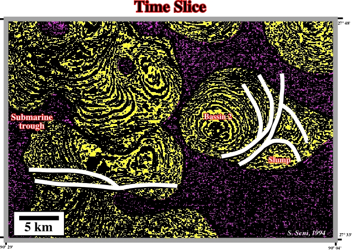
Fig. 314- On this time slice several salt expulsion basins (yellow) are visible within an allochthonous salt nappe. The sediments filling these basins are slightly discordant against the salt walls. In red, are picked normal-faults extending the sediments of the mini-basins.
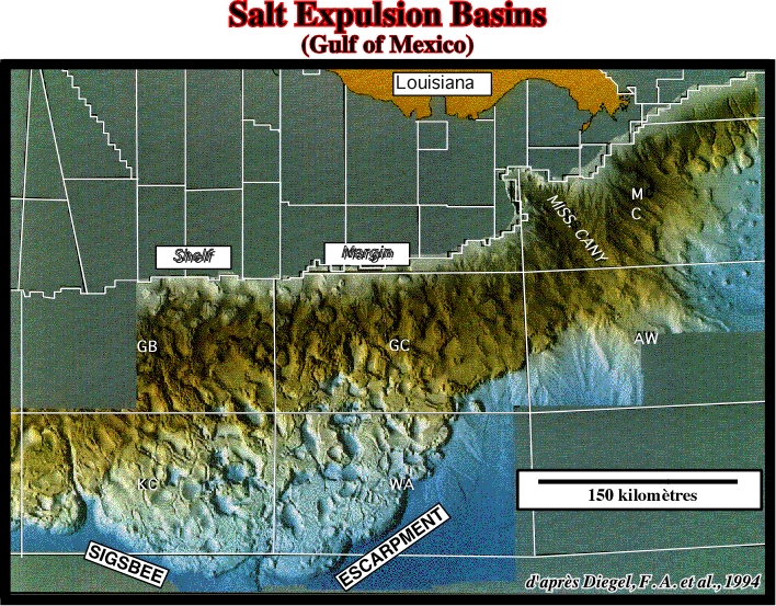
Fig. 314- On this sea-bottom presentation of the central part of the Gulf of Mexico, salt expulsion basins are underlain by circular negative anomalies (bathymetric depressions), which match the sedimentary depocenters illustrated on the previous figure.
The mechanism of development of salt expulsion basins is depicted on the sketch below (fig. 315).
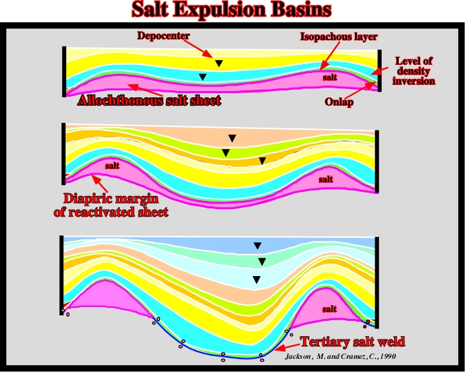
Fig. 315- Take into account the allochthonous salt sheet (in pink), which can be of 1st or 2nd generation and the overlying isopachous interval (in light green), which indicates the sedimentary thickness under which the allochthonous salt was put in place, the reactivation of the salt induced: (a) diapiric margin structures, (b) depocenters and (c) a tertiary salt weld between the diapiric structures. The salt expulsion basins correspond to the depocenter, in which the lateral displacement of the maximum thickness corresponds to the variation in salt flowage the salt.
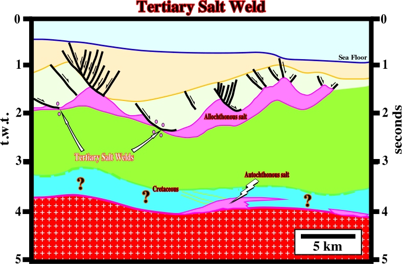
Fig. 316- In a dip section, roughly parallel to the salt flowage, salt expulsion basins show a geometry totally different of the one represented in the sketch of fig. 315. The previous sketch was built using a strike line. The next figures (fig. 317-318) represent perpendicular lines through a salt expulsion basin.
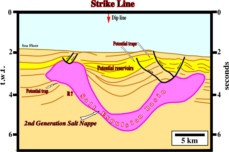
Fig. 316- This figure represents the interpretation of strike line through a salt expulsion basin. It crosses a dip line (fig. 317). Strike lines, as this one, show well the depocenter forming the mini-basin. Potential morphological traps by juxtaposition associated with the normal faulting, or with the walls of the marginal diapirs are possible. Potential morphological traps associated with the external flanks of the marginal diapirs (outside of the mini-basin) are also likely. The first type of traps requires the existence of a tertiary salt weld allowing an eventual migration of the hydrocarbons toward the salt expulsion basin.
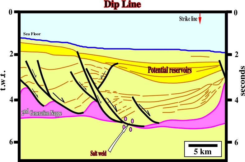
Fig. 317- This interpretation shows the longitudinal morphology of the salt expulsion basin and the evidence of the down-dip flowage of the allochthonous salt sheet, which created a tertiary salt weld (salt window), which allows migration of the hydrocarbons generated by sub-allochthonous salt potential source rocks.
Tertiary salt welds are easier recognized in dip lines than in strike lines. Therefore, the evaluation of the hydrocarbon potential of a prospect within a salt expulsion basin requires an exhaustive interpretation of all lines, particularly the dip lines and salt welds, in which migration paths are easier to recognize. The other hydrocarbon parameters are often present. Sandstone turbidite reservoirs are quite abundant in this type of basin. Explorationists have invoked several sedimentary models explaining the abundance of reservoir in mini-basins. Among them, there is one, where the turbidite currents jumping from mini-basin to mini-basin in a similar way as they jump in a foredeep basin context (fig. 318).
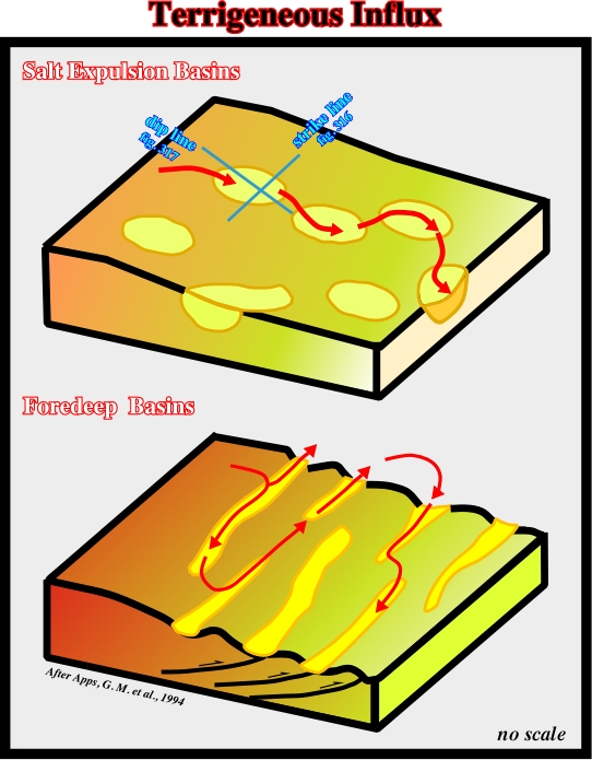
Fig. 318- On this depositional model, due to the bathymetric anomalies (see fig. 314) on the continental slope, the turbidite currents do not have high degree of freedom. They do not have a shelf organized critically (SOC) behavior. Therefore, amalgamated deposits take place in each mini-basin. However, in a clastic setting, the sand-shale ratio decreases down-dip. Similarly, in a deep-water foredeep or fold belt settings, as those found in the distal areas of the salt divergent margin (Angola, Campos, Gulf of Mexico), the same depositional model is likely. The major difference is the orientation of the depocenter. In a salt expulsion basin, they generally show a down-dip alignment, while in a contractional geological context, the alignment is roughly parallel to the shelf break.
to continue press next
next

Send E-mails to ccramez@compuserve.com or cramez@ufp.pt with questions or comments about these notes.
Copyright © 2001 CCramez
Last modification:
Março 19, 2006