Porto, Portugal
3- Growth of Salt Domes (cont.)
3.11- Autochthonous and Allochthonous salt
Goguel (1983) with an ingenious experience (fig. 103) showed the more likely evolution of an unstable salt layer with time. It suggested how an autochthonous salt layer (mother salt layer) can generate allochthonous salt layer, as in fig. 101.
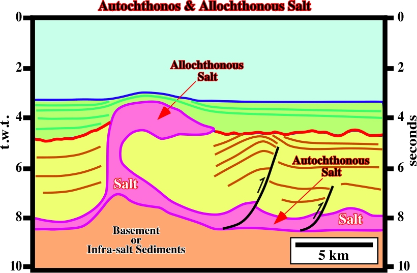
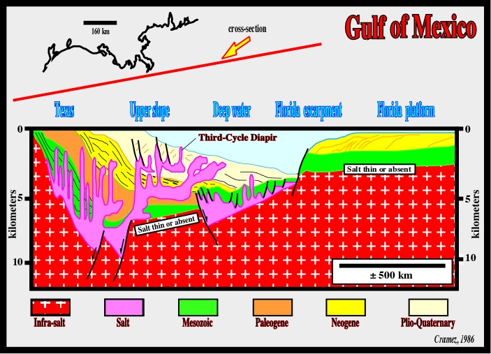
Fig. 102- On this line deepwater seismic line of Gulf of Mexico, autochthonous salt, that is to say, salt resting on the original strata on which it accumulated and allochthonous salt (salt emplaced at stratigraphic levels above the autochthonous source layer) are easily recognized.
Goguel, in his experiment, using an aquarium, superposed two liquids with different density, to simulate a mother salt layer and an overburden:
(i) At the bottom, he poured oil (the lighter liquid), and (ii) At the top, he poured water, the denser liquid.
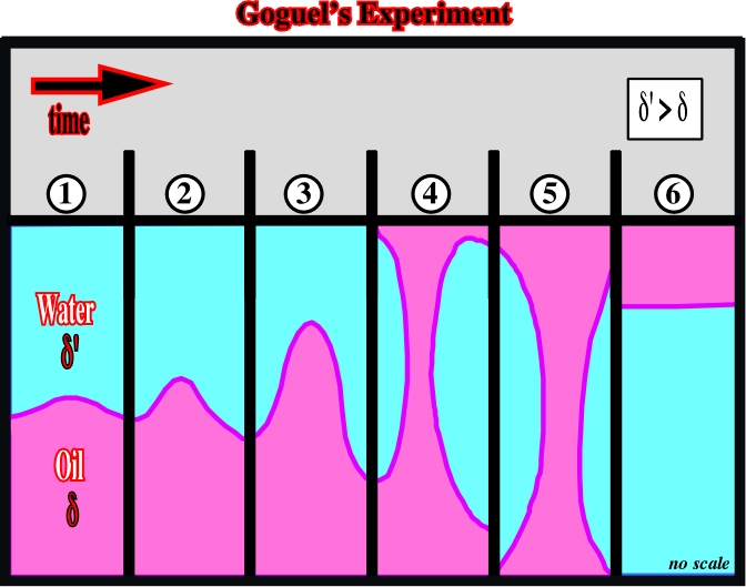
Such a situation, i.e. a lighter fluid under a denser one is an unstable situation. Thereby, with time, the lighter fluid will become to surface, while the denser goes to the bottom. During such an inversion, several steps or stages can be considered:
a) Small Positive Anomalies: at the oil-water interface small equidistant (Rayleigh-Taylor instability) anomalies develop (1 in fig.103).
b) Mound Stage: the anomalies grow-up forming mounds characterized by its relatively flat flanks (2 in fig. 103).
c) Dome Stage: growing, the mounds become domes. Their flanks reach a quite high dip, near the vertical (3 in fig. 103).
d) Post-Dome Stage: since a dome arrives at surface, the oil starts to flow laterally, creating post-dome structures; some of these structures become disconnected from the mother oil layer (4 and 5 in fig. 103).
e) Canopy Stage: at surface, the oil flowing in opposite direction creates canopy structures similar to those created by ascendant convection currents (5 in fig. 103).
f) Stable Stage: Finally, all oil will be transferred at surface, reaching an equilibrium state (6 in fig. 103).
The last three steps simulate the development of allochthonous salt layers, which can be connected or disconnected with the mother salt layer.
Using a centrifuge, M. Jackson (1986) simulated the different steps of salt diapirism and the formation of the allochthonous salt nappes of the Gulf of Mexico (fig. 104).
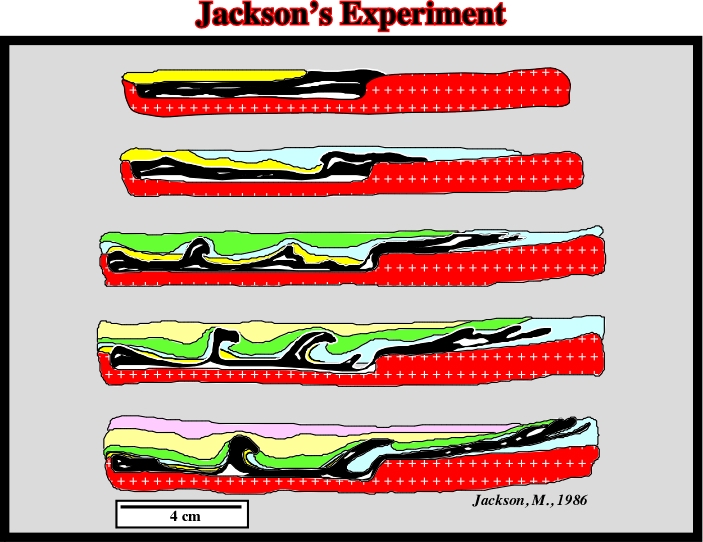
In this simulation, where several stages (fig. 104) can be considered, one must take into account:
1) The presence of an important step on the infrastructure.
2) The black layer simulates the salt.
3) The black layer flows laterally and vertically due to the loading of the yellow layer.
4) The extension of the yellow layer does not exceed that of the black layer.
5) The extension of the blue layer, exceeds that of the black layer.
6) The loading of the blue layer obliges the black layer to flow vertically and slightly rightward.
7) The depocenters of the green layer not only force the black marker to form intrusive domes, but intrusive nappes as well. They are clearly intruded and cut the blue layer.
8) The diapiric mechanism and the allochthony of the black layer continue with the deposition of the upper layers.
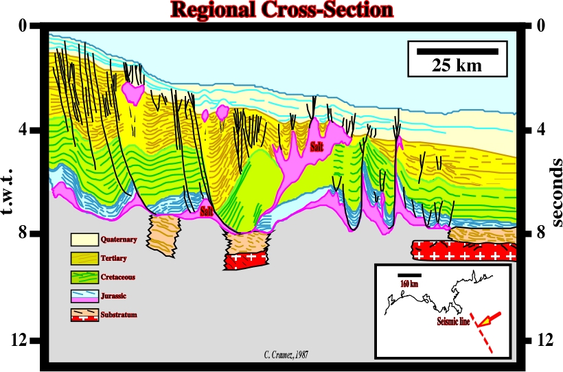
The final result is quite similar to that that geologists deducted from the geological interpretation of the regional lines whether:
(i) In Gulf of Mexico (fig. 105) or
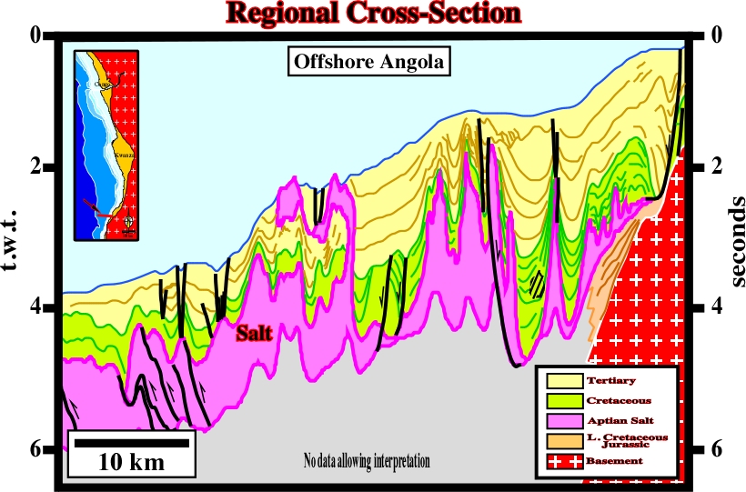
(ii) In offshore Angola (fig. 106).
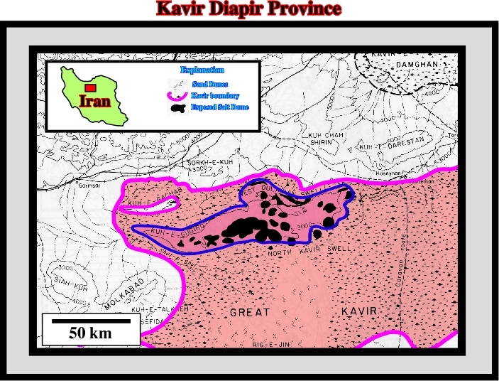
Iran is exceptionally rich in evaporite deposits. They were deposited episodically throughout the Phanerozoic. The best known evaporites are the Infracambrian Hormuz salts (800 to 500 Ma) of the southern Zagros and Persian Gulf region and their equivalents in Central Iran, the Permo-Triassic anhydrite of the Gulf and Coastal Zagros, the Upper Jurassic evaporites in the Gulf region and eastern Central Iran, the Lower Fars (Miocene) salt of the Zagros, and the Tertiary salts of the Great Kavir basin in Central Iran (fig. 107), which has a unique abundance of exposed salt diapirs.
In 1992, M. Jackson, proposed few geological cross-sections of the exposed salt domes. In addition, adopting critical scientific approach, he hypothesized two different possible, and opposite, geological evolutions for the Kavir diapir province:
(i) Diapirism without Posterior Folding and
(ii) Folding followed by Diapirism.
These opposite hypotheses that will be described here after are quite interesting. Indeed, in the majority of the salt basins, geologists must always decide whether the salt structures were just induced by halokinesis or by salt tectonics. If an extensional, or compressional, tectonic regime is also responsible by the final result. Actually, in these notes, this problem will be tackle several times (offshore Angola, Gulf of Mexico, North Sea, etc.). The petroleum exploration implications are quite different.
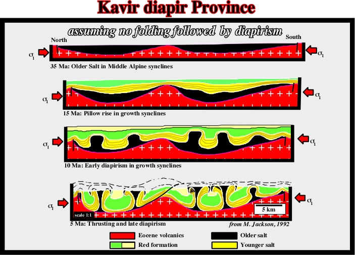
On this hypothesis (fig. 108), M. Jackson proposed:
a) Around 35 Ma (notice that 35 Ma means 35 million years ago, that is to say, a geological age and 35 My means an interval whether Cretaceous or Paleozoic of 35 million years) , the older salt (in black) was deposited in Alpine synclines.
b) After the deposition of the young salt (in yellow), mound structures rise within the growth synclines.
c) At 10 Ma, domes structures are predominant.
d) Around 5 Ma, late diapirism creates canopies and thrusting.
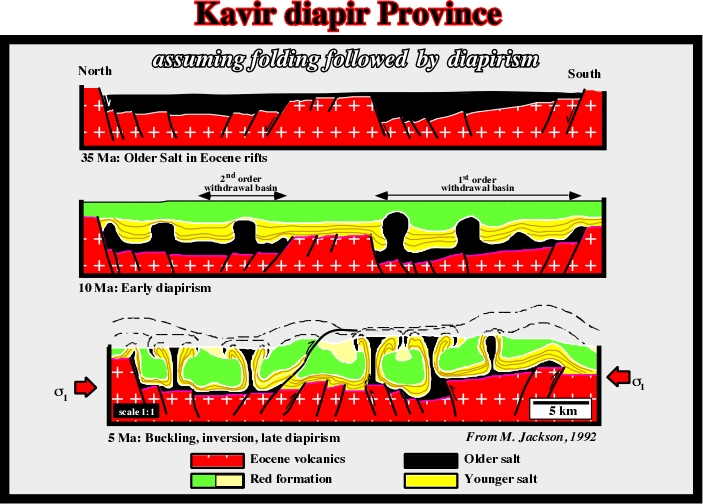
The alternative hypothesis (fig. 109) implies a shortening and folding after diapirism in order to explain the formation of salt canopies. It can be summarized as follows:
a) At around 35 Ma, an extensional tectonic regime creates rift-type basins, which were filled by older salt (black).
b) At the Upper Miocene, first in the southern rift-type basin, and then in the northern basin, the older salt started to move during the deposition of the younger salt. Mounds and domes were developed.
c) During the Pliocene, a compressional tectonic regime took place and shortened the rift-type basins:
- The Oligocene normal-faults, which have created the rift-type basins, were reactivated as reverse faults inducing tectonic inversions.
- The salt layers as well as sediments were folded, what facilitate a late diapirism of the salt layers with development of canopy structures.
Contrary to autochthonous salt, where salt bodies rest more or less on the original strata or surface on which they accumulated, allochthonous salt comprises sheet-like salt bodies emplaced at stratigraphic levels above the autochthonous mother salt layer. As was suggested by several authors, the term allochthonous salt is applied even if the salt sheet remains attached to its source layer. M. Jackson (1991) evoked two main reasons for this liberal definition:
I- Allochthonous salt is transported from its original position and rests on a different substratum regardless of whether its roots remain attached.
II- Determining whether a salt sheet is detached or connected by only a thin stem is generally impracticable, even with modern seismic data.
Therefore, the terminology for allochthonous salt structures (fig. 110) cannot be definitive. Several overlapping terms are currently in use. The terminology proposed by the Sub-commission on Tectonic Nomenclature (International Union of Geological Sciences) is illustrated in fig. 110. It will be followed in these notes.
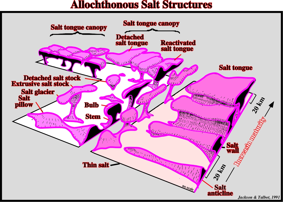
Fig. 110- Block diagram showing the majority of the allochthonous salt structures. The structural maturity and size increases toward the composite, coalesced structures in the background.
A salt sheet is a broad, non-genetic term that can be defined as any allochthonous salt structure whose breadth is several times greater than its maximum thickness. Therefore, it can include salt tongues, salt laccoliths and salt sills (fig.111 & 112).
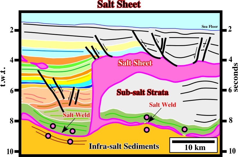
Fig. 111- This single rooted allochthonous salt structure can be considered a salt sheet.
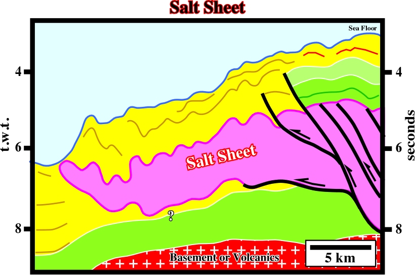
Fig. 112- Reactivated (shortened) salt sheet located westward of the salt basin limit in deep water Angola.
A salt laccolith is an intrusive salt sheet that has a ratio of maximum width to maximum thickness (arbitrarily and tentatively) less than 20. Its upper contact is typically concordant, whereas its lower contact is commonly slightly discordant (fig. 113 & 114).
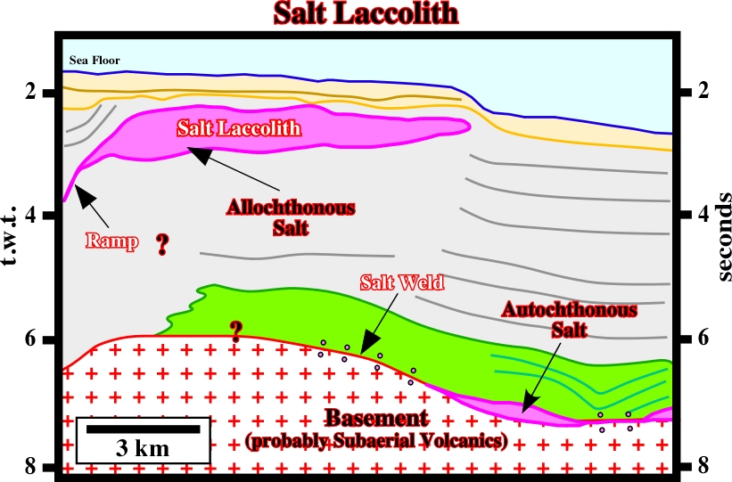
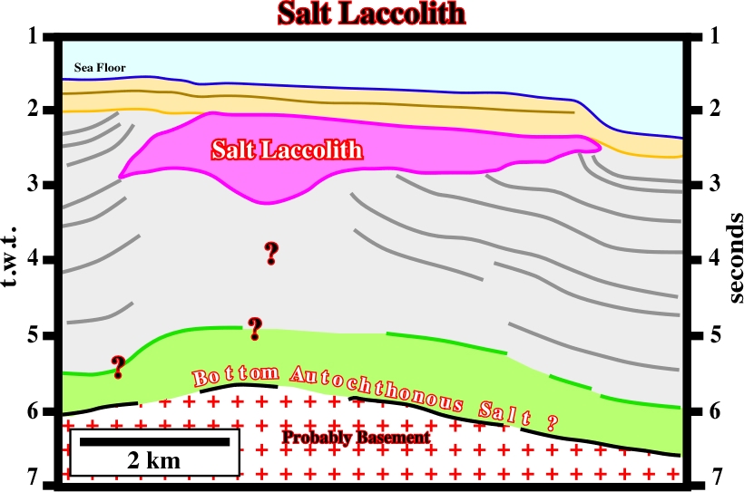
Fig. 114- This allochthonous salt structure can be also considered a detached laccolith.
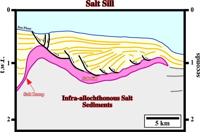
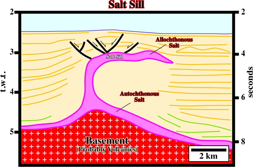
A salt sill is an intrusive salt sheet that has a ratio of maximum width to a maximum thickness (arbitrarily and tentatively) more than 20. It is typically intruded at depths of only a few hundred meters or less. Contact relations are similar to those of a salt laccolith (fig. 115 & 116).
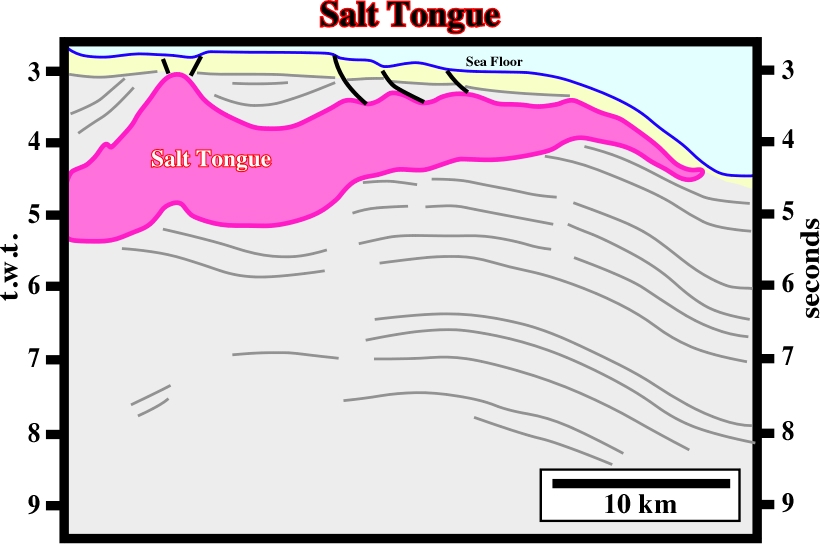
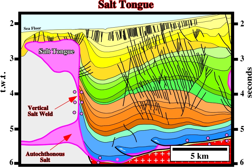
A salt tongue is a highly asymmetric variety of salt sheet or salt laccolith fed by a single stem. Individual salt tongues are as much as 80 km long and 7 km thick. This term is typically applied to wedge-like bodies having tapered angles and do not resemble a salt still (fig. 117 & 118).
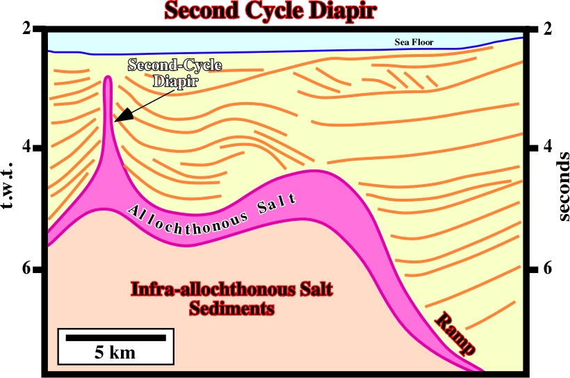
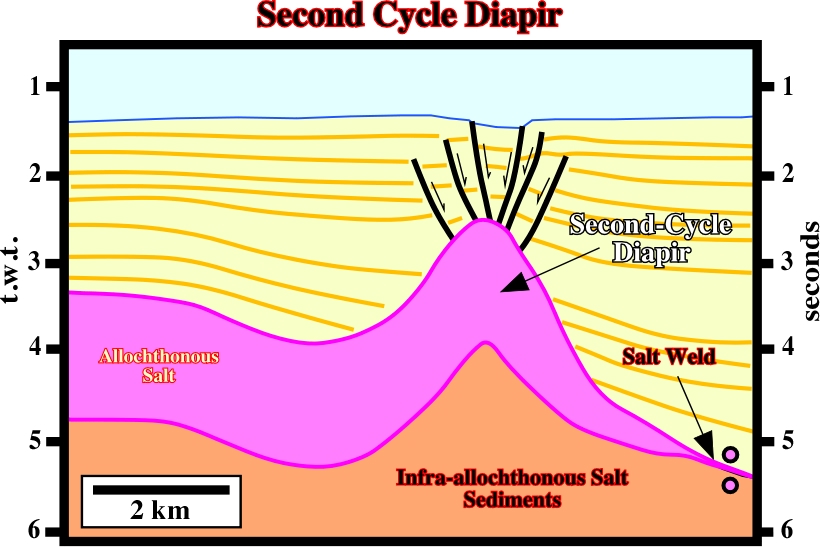
A secondary-cycle diapir is a diapir that rises by reactivation of allochthonous salt (fig. 119 and 120).
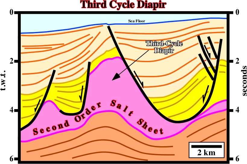
A third-cycle diapir is that which rises from salt sheets derived from still older salt sheets that have also been inferred in the basin (Fig. 121 & 122).
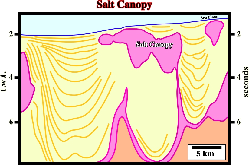
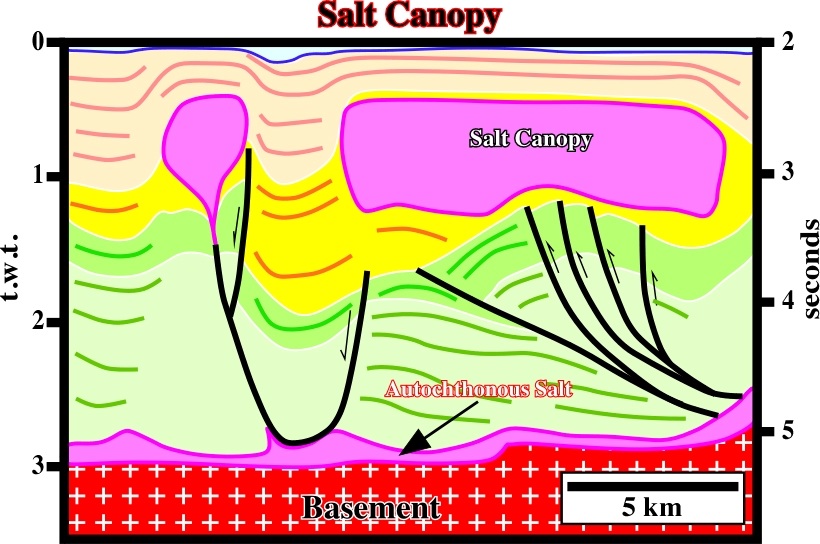
A salt canopy is a composite diapiric structure formed by partial or complete coalescence of diapir bulbs or salt sheets. These bodies coalesce along salt sutures and may or may not, be connected to their source layer by feeder stems (fig. 123 & 124).
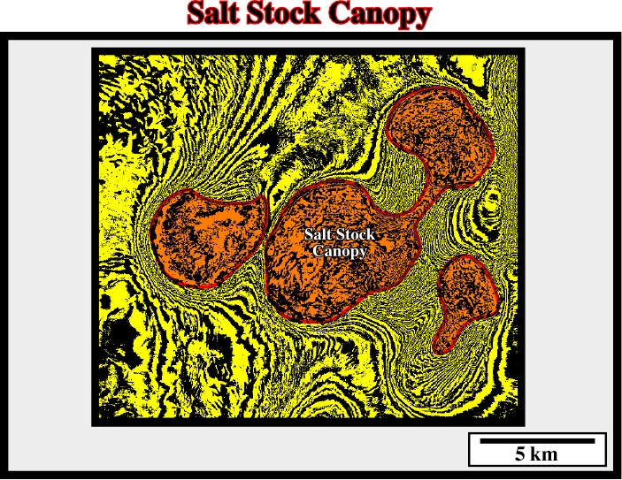
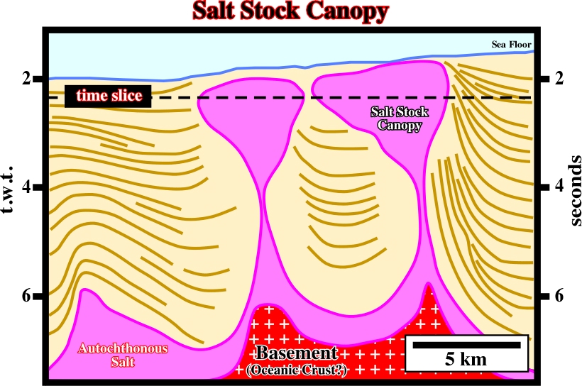
A salt-stock canopy is a salt canopy, which forms by coalescence of stocks, that is to say, of plug-like salt diapirs having sub-circular planform (fig.125 & 126).
A salt-wall canopy is a salt canopy that forms by coalescence of salt walls (fig. 127 & 128).
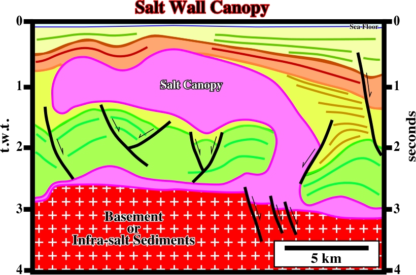
Fig. 127- This salt canopy is the result of the coalescence of the two parallel salt walls.
A salt-tongue canopy is a salt canopy that forms by coalescence of tongues.
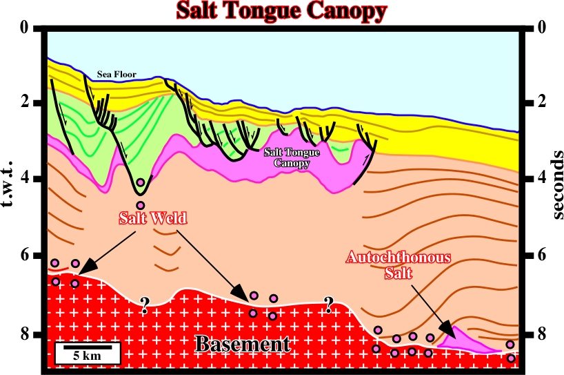
Fig. 128- This reactivated canopy is the result of the coalescence of at least two salt tongues.
A salt suture is a junction between individual salt structures that have coalesced laterally to form a salt canopy. Incomplete sutures have lens overburden along them. Complete sutures have folds in the overburden above them; either the suture is below a subsided, cuspate synforms, or it is the junction of a pair of oppressed, raised salt antiforms. (fig. 129 & 130).
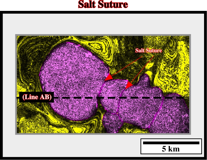
Fig. 129- Several salt sutures are evident on this time slice (see seismic line below, fig. 130).
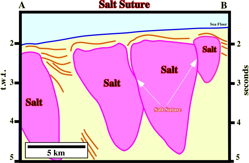
Fig.130- Two salt sutures are illustrated on this seismic line (see time slice for location).
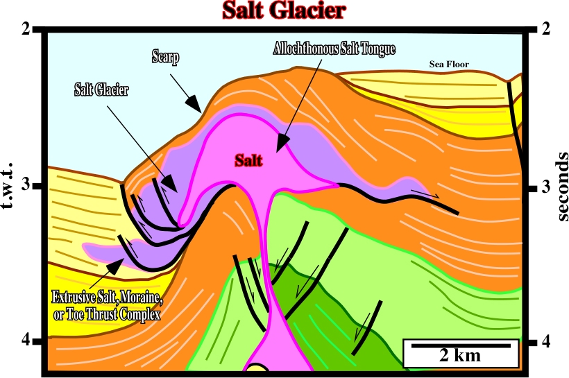
A salt glacier, or namakier, is a sheet-like extrusion of salt flowing from an exposed diapir and spreading beneath air or water (fig. 131 & 132).
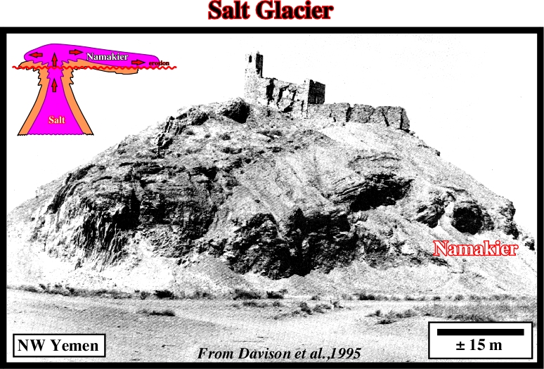
Fig. 132- On this line from deep water Angola, it is likely that when the salt became extrusive, it flowed laterally along the sea floor, as a glacier, before being squeezed.
to continue press
next
![]()
Send E-mails to ccramez@compuserve.com or cramez@ufp.pt with questions or comments about these notes.
Copyright © 2001 CCramez
Last modification:
Março 19, 2006