Porto, Portugal
Contents: 5.1- Basement Involved 5.1.2- Extension (1 vertical) Generalities a) Sequence of geological events b) Dip of beds and dip of faults c) Angle between the fault plane and the vertical d) Depth of a detachment surface e) Amount of extension f) Ends of a normal fault g) Normal faulting deformation h) Intermediated fault blocks i) No planar faults j) Deformations in no planar faults k) Associated grabens 5.1.2.1- Positive Tectonic Stress (
5.1- Basement involved (cont.)
a) Sequence of geological events
During an extensional tectonic regime the sequence of geological event can be summarized as follows:
Extension.....Lengthening.....Subsidence.....RSL Rise.....Sedimentation
In other words, when s1 is vertical the sediments are lengthened, which implies subsidence. Subsidence creates a relative sea level rise, i.e. increases accommodation and, generally, there is deposition. This sequence is quite different of the one induced by a compressional tectonic regime (shortening, uplift, relative sea level fall, erosion, unconformity), which ends by erosion of the sediments deposited during the previous extensional regime.
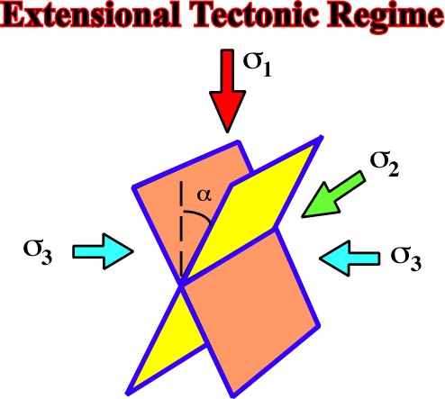
Fig. 162- In an extensional tectonic regime, the maximum effective stress (
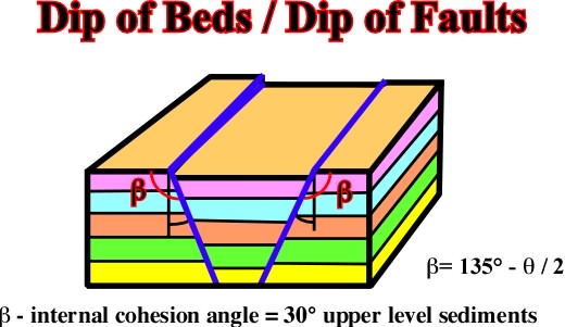
Fig. 163- In the upper levels of the ground, the dip of conjugated normal faults ranges between 60-70°, while the dip of conjugated reverse faults ranges between 30-40°. The dip strike slip faults is sub-vertical. Such a criterion (Anderson's law) is particularly useful in geological interpretation of seismic lines. For that, a roughly depth conversion at natural scale (1:1) is often enough. Vertical normal faults do not exist, even if, locally, the dip can be near 90º. In fact, as normal faults are developed in order to length the sediments, a vertical normal fault is against all Nature's laws. It cannot length or short and, in addition, it implies a crucial volume problem, since there is no space on the ground (void) allowing a vertical throw.
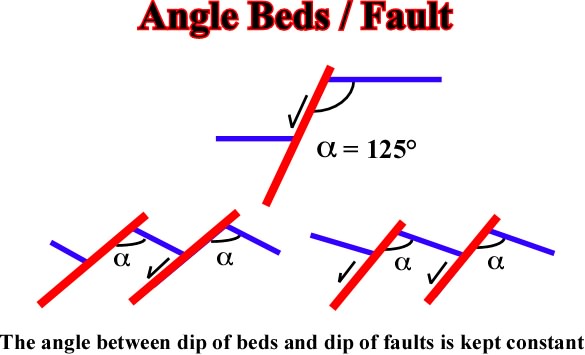
Fig.164- As illustrated on this sketch, the angle between a normal fault plane and the beds composing the footwall and the hangingwal is keep roughly constant, either when the throw changes or or when the sediments are tilted.
c) Angle between the fault plane and the vertical.
In a normal fault, the hade, that is to say, the angle that a structural surface makes with the vertical (measured perpendicularly to the strike) or the angle a between the fault plane and the vertical, is constant (fig. 165).
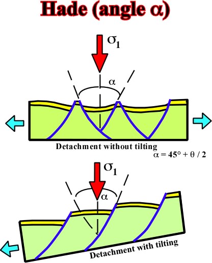
Fig. 165- In normal faulting, the hade, which is the complement of the dip, is constant. In the upper sketch, where the detachment plane is not tilted, it value is represented by the angle a ( more or less equal to 45º plus half of the internal cohesion angle b). As illustrated in the lower sketch, the hade is the same, even when the detachment plane is tilted.
d) Depth of a detachment surface
The depth of detachment surface of a listric fault is related with:
(i) Length of blocks (L).
(ii) Rotation of blocks (dip).
(iii) Cartography of the fault plane.
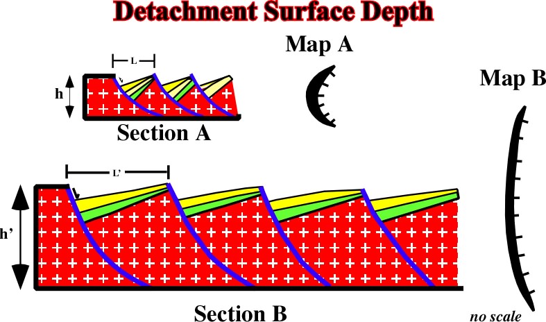
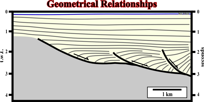
Fig. 166- Larger are the fault blocks, smaller is the rotation of the blocks and so lower is the detachment surface and less curvilinear is the cartography of the fault plane. Such empiric statement can easily be corroborate on seismic lines, particularly those shot in areas affected by a thin skinned extension, as illustrated below (fig. 167).
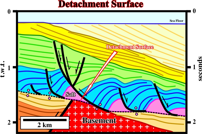
Fig. 167- On this seismic line a detachment surface associated with the base of a mobile layer (allochthonous salt) created a sharp tectonic disharmony. The sediment overlying the tectonic disharmony were deformed in a complete different way of those below it. The overlying sediments were lengthened by curvilinear normal faults dipping downdip with a more or less constant angle (the hade increases slightly in depth, but not too much). The fault blocks show roughly the same rotation and, in a map, the fault planes have more or less the same geometry.
In listric faults (curvilinear faults), there is a typical relationship between the slip throw and the amount of extension as illustrated in fig. 168.
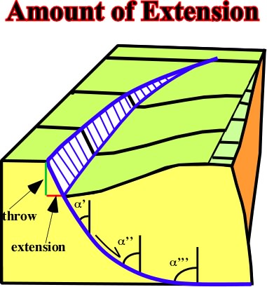
Fig. 168- In listric normal fault, the change of vertical displacement (throw) is associated with the rotation of the downthrown blocks and with the amount of extension. At the ends a fault the extension is zero. Notice how the hade increases with the depht pf the fault plane. It reaches 90º when the detachments surface becomes horizontal.
The conseqeunces of the relationships depicted above are:
(i) The depth of the ends of fault plane, in the downthrown block, is minimum; there is no extension.
(ii) At the ends of a fault plane there are not upthrown and downthrown blocks; there is no fault, so the throw and extension are nil.
Two zones of differential movement are developed at the ends of fault planes (fig. 169).
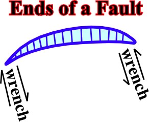
Fig. 169- As at the ends of a fault there is no extension, and so, no throw, the presence of a unique fault is impossible since it creates differential wrench movements. In other words, to extent (lengthen) a certain area of 10%, for instance, several normal faults are necessary to avoid wrench deformations., i.e. to create an homogeneous extension.
To avoid wrench movements during extension (see fig. 169), normal faults can be display in two different ways:
1) Relay display, 2) Transfer display
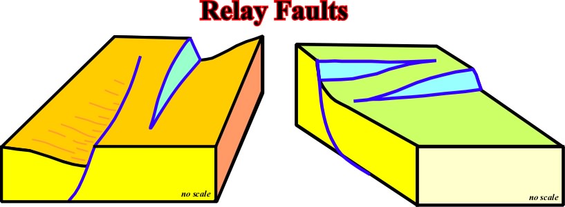
1) Relay display (fig. 170)
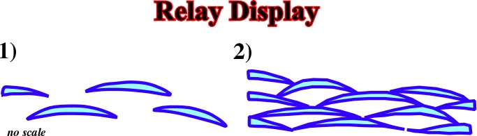
Fig. 170- The large majority of the normal faults are curvilinear. When they look rectilinear is just a question of scale. So, one can say when normal faults are display in relay, the lengthening of the area is homogeneous. Indeed, since along the
Fig. 171- In relay faults the maximum of extension of a fault fits with the minimum of extension of the nearby fault, in order to give an homogeneous extension of the area, i.e. avoid differential wrench movements near the ends of the faults (see fig. 172).
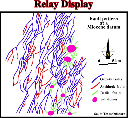
Fig. 172- On this structural sketch, the growth faults (in bleu) are displayed in relay, which gives an homogeneous seaward extension. Note the antithetic faults (red), as well as the radial faults (green) associated wont the salt domes. The radial faults were developed by local extensional tectonic regimes (
2) Transfer display (fig. 173)
In a transfer display, extension is tranfer from a fault to the nearby by transfer faults. So, transfer faults are extensional strike-slip faults (fig. 174). They have higher dips than the associated normal faults and, generally, they show, on the discontinuity planes, slickensides with horizontal and downward displacement.
![]()
Fig. 173- In a transfer display, as illustrated on this sketch, at the end of a fault, extension is transfer to a nearby normal fault, buy a a vertical and rectilinear zone called, often, transfer fault, as shown in block diagrams below (fig.174).
![]()
Fig. 174- Transfer fault allows extension to be transferred to other normal faults. In these examples,one can see that they are extensional strike slip faults wit a vertical or almost vertical fault plane (see fig. 175).
![]()
Fig. 175- In these block diagrams, based on seismic data of offshore Japan, it is easy to understand the role of transfer faults in the lengthening of the non-Atlantic type and Atlantic-type divergent margins (fig. 176).
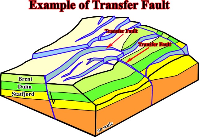
Fig. 176- In N\orth Sea, detailed structural maps show very often that extensional accommodation was obtain by the development of transfer faults as in this particularly example coming from a Total's field.
In the block diagram below (fig. 177), is depicted a nice example of what some structuralists (geologists studying Structural Geology) call an helical structure, which is cretaed between the ends of parallel faults with opposite vergence. Indeed, one can recognized:
(i) An helical synform, and not antiform, between normal faults with opposite vergent with small stretching faults on the top of the structure.
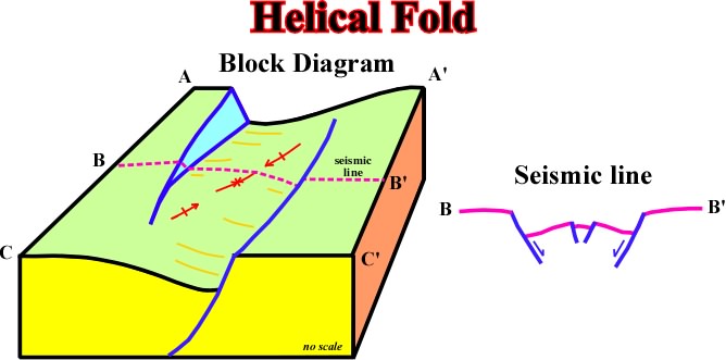
Fig. 177- This block diagram illustrated an helical fold, which is often used by funny geologists to farmout areas characterized by an absence of hydrocarbon traps. Indeed, as one can easily notice, in 3D, the apex of the structure, bounded by the opposite vergence normal faults, is a structural low and not a high.
(ii) In spite of the fact, that the majority of transversal seismic line crossing an helical structure show an antiform structure, the central zone, underlined by the arrow (in red), is not a longitudinal structural high, but a structural low.
(iii) The stretching faults developed near the apex of the structure, as illustrated by the seismic line B-B', apparently suggest the possibility of a potential traps for hydrocarbons. However, explorationists should not forget the apex is a structural low, so it is almost impossible to have an hydrocarbon trap. The chrono-stratigraphic lines updip toward the fault ends, where extension is zero.
Very often, normal faults, developed by different extensional tectonic regimes (different
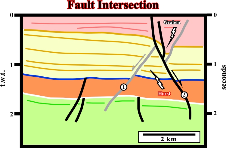
Fig. 178- This seismic line illustrates the displacement of a normal fault by another normal fault of different age. Admittedly, the faults dipping to the left (in green) are older than the faults dipping to the right (in red), i.e. the green faults were displaced downward and rightward by the younger faults. Such a displacement created, in the same vertical, a graben above a horst. This geometry, called by some as "X-faults" is typical of such intersections faults.
On the other hand, interpreters must also recognize how the dip of a fault plane can be affected by lithological changes in the fault block. These changes, induced by differential compaction associated to the facies, can be used to suggest lithological prediction. In fact, in a sand-shale realm, such in Gulf of Mexico, it is possible to predict the lithology of the footwall using rollover or sag geometries recognized on thhangingwall (fig. 179).
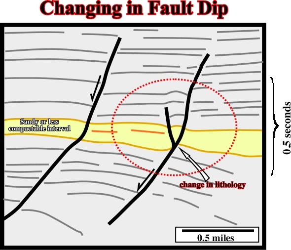
Fig. 179- As illustrated on this seismic line, the dip of a fault change all along the fault plane. Such a change is mainly induced by compaction of the sediments which implies a pre-compaction faulting (see below, (i) no planar faults).
Similarly, explorationists, and particularly seismic interpreters, should not forget the geometry of seismic markers is, also, dependent on the angle between the seismic profile and the strike of the fault planes, as illustrate on the sketch below (fig. 180).
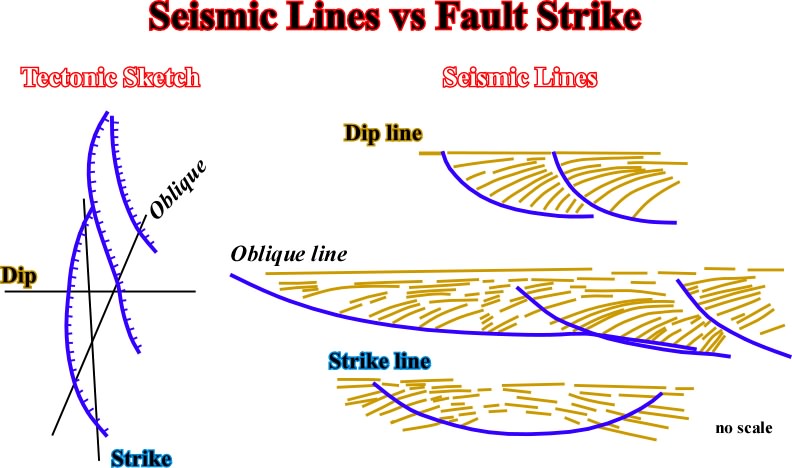
Fig. 180- On a seismic line, the geometry of the reflectors is largely depend of the angle between the profile and the strike of the faults. The more representative geometry is the one recognize on dip lines, i.e. lines perpendicular to the strike of the fault and sediments. Indeed, in oblique and strike lines, the geometric relationships between the reflectors themselves or between the reflectors and the disconformities are apparent as illustrated on the seismic line below (fig.181).
Fig. 181- On this slalom seismic lines, i.e. a non rectilinear line, the faults planes are intersect at different angles. So, the geometry of the reflectors, particularly in the hangingwal are quite different. The more representative is the one where the rotation of the hangingwall is more homogeneous and higher, that is to say the hangingwall on the right.
g) Normal faulting deformation
Deformation associated with normal faulting is mainly concentrated on the hangingwall near the fault plane as illustrated in fig. 182.
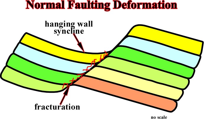
Fig.182- In a normal fault, due to the relative downward movement of the hangingwall, the bedding planes are slightly deformed and fractures, often to fill the space created by the lengthening.
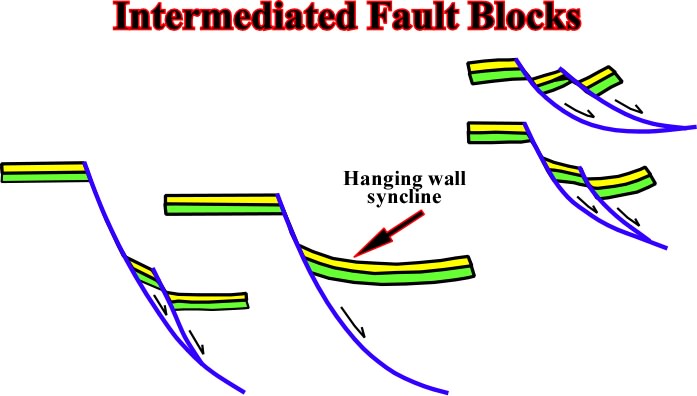
Fig. 183- Very often, in order to accommodate the hangingwall sediments to the new volume conditions, intermediated fault blocks are developed. They are limited down dip by the major fault and due to the rotation of the major faulted blocks, they can dip toward the downthrown block, or in opposite sense (fig. 184).
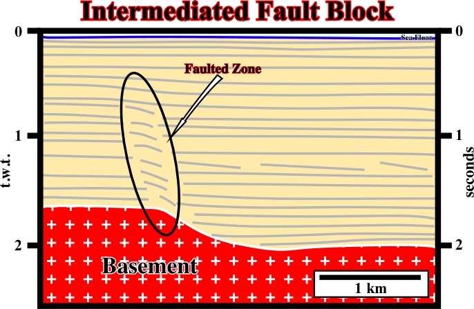
Fig. 184- On this seismic line, the sediments were lengthened by a normal faulting. However, due to the lack of rotation of the hanging wall, the development of an intermediated fault block was necessary to solve volume problems, i.e. potential voids.
Volume problems associated with no planar fault planes are solved by a width deformed gouge zones, where drag blocks are orientated parallel to the fault planes and rotated downwards (fig. 185).
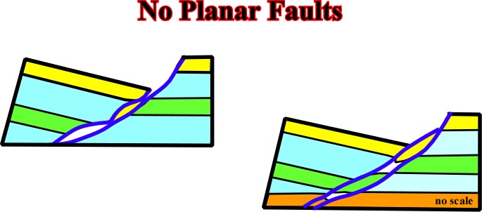
Fig. 185- As illustrated, in no planar faults, volume problems can be solved by the dev elopement of a gauge zone between the fault blocks. However, the majority of the sediments of such a deformed zone come from the hangingwall,
No planar fault planes could result from the different mechanical properties of sediments, anisotropies or differential compaction (see also fig. 179, as illustrated on the following sketch:
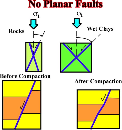
Fig. 186- As illustrated, the angle between two conjugated normal faults depends either on the sediment's rheology or on the differential compaction. Indeed, when normal faulting is pre-compaction the dip of the fault planes, after compaction, can change a lot. It depends on then compactability of the sediments. Admittedly, shales are much more compatable than sands, so, the dip of fault planes in sandy sediments will high han in shaly facies (fig. 187).
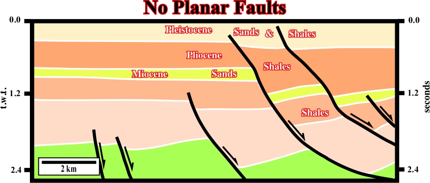
Fig. 187- On this seismic line from the Gulf of Mexico, the interpretation is redundant. The geometry of the fault planes clearly indicates a change in facies (sand / shales) of the stratigraphic intervals. In fact, the lithology of the Neogene sediments of the Gulf Coast is fundamentally an interbedding of shales and sands, and the sandy interval are lesser compatable than the shaly.
j) Deformations in no planar faults.
In no planar faults one can recognize, in the downthrown block, several kinds of deformations: (i) rollovers, (ii) hangingwall synclines, (iii) grabens, (iv) small tilted blocks, as illustrated in the following figures (fig. 188-190):
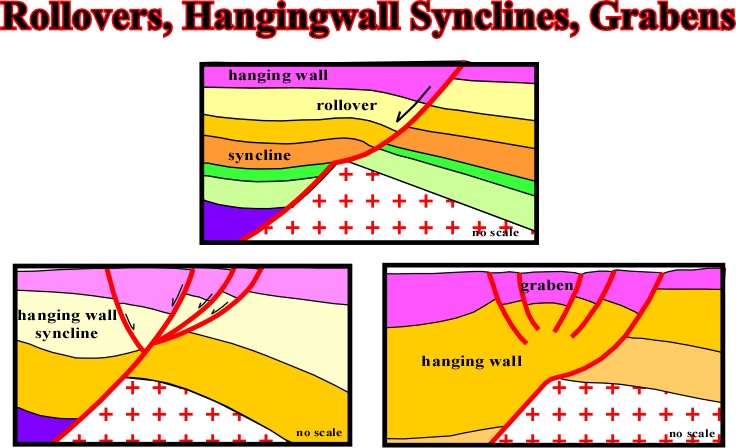
Fig. 188- The change in lithology, between the basement and sediments, in the footwall created in the hangingwall a volume problem. Subsequently, the sediments were obliged to extend to avoid potential voids. THus rollovers, hangingwall synclines and graben were developed in the downthrown block.
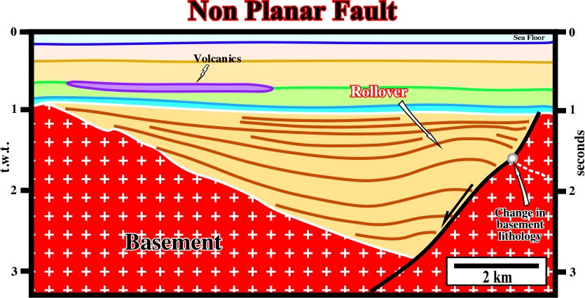
Fig. 189- The normal fault limiting this half-graben (rift-type basin) is no planar. The change of the dip of the fault plane is created by a lithological changing in the basement (Paleozoic rocks), Such a dip change created a volume problem in the half-graben and so the sediments were lengthened by a rollover structure, which indicates roughly the position of the lithological change (intersection of the axial plane of the rollover with the fault plane). Notice that on this seismic line the major fault is underlined by a more or less continuous reflector due to the great impedance contrast between the rift-type basin sediments and the basement.
When sediments are extended by regional or local tectonic regimes, the development of graben-type structures appears very often to accommodate the sediments to the new volume conditions, i.e. to lengthened the sediments to fill all space created by extension, as illustrated in fig. 190.
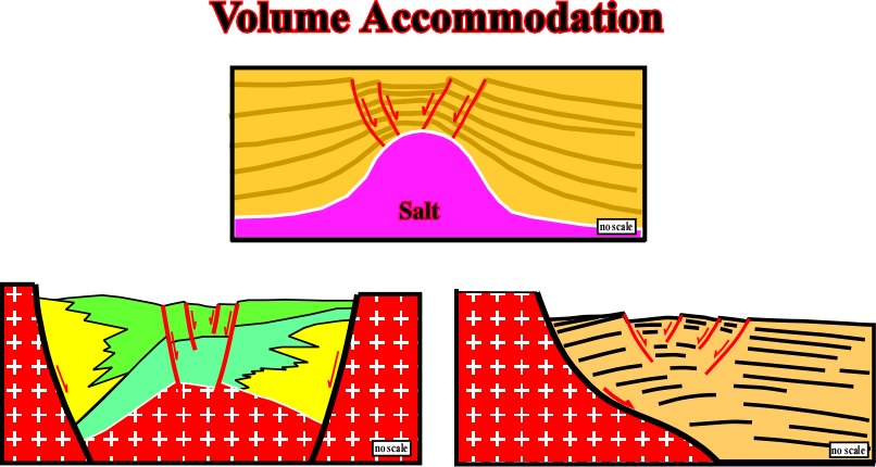
Fig. 190- In this figure are represented three typical examples of volume accommodation, in which the sediments were lengthened to fill the potential voids created by extension. Above, a salt diapir elongated the sediments in the top of the diapiric structure and so the sediments were lengthened by radial faults. Below, the right sketch illustrated, as the previous seismic line, how the geometry of ea fault limiting a rift-type basin can created a rollover, i.e. an antiform (extensional structure) with the associated stretching normal faults. Finally, the sketch on the left, is a typical example of the type-rift basins in onshore Sudan, where a Cretaceous extensional tectonic regime was followed by a Lower Tertiary extensional regime. The final result was the formation of half graben structures with opposed vergence which, when combined, give an apparent graben structure with a helical geometry, in which is almost impossible to find structural traps (four-way dips) associated with this kind of deformation.
5.1.2.1- Positive Tectonic Stress (s t > 0)
When the tectonic stress is positive, but
Fig. 191- In this tectonic regime, in which the sediments are lengthened, the chiefly extensional structures are graben or half-graben trending parallel to
a) Normal Faults -Grabens
On a scale of hundred of kilometers, at a given time, a lessening of the stresses and consequently of the deformations, is observed. Indeed, far enough from the area of compression, the tectonic stress can be positive but smaller than the geostatic stress. This implies a vertical
Overthrusts -- Folds -- Strike-slip Faults -- Grabens
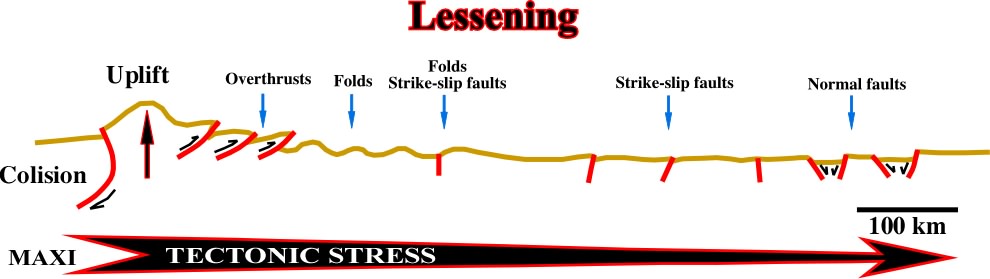
Fig. 192- Generally, this sequence of deformations (overthrusts -- folds -- strike-slip faults -- grabens) is interpreted as a result of relaxation of the tectonic stress (lessening of tectonic stress). Actually, as explained by J. Goguel, within a lithospheric plate, the tectonic stress is more or less constant. There is not lessening of the tectonic stress but just local changes in the sediments' threshold deformation (rheological behavior) function of temperature and pressure.
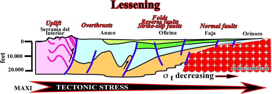
Fig. 193- This geological cross section from Guyana shield to Serrania del Interior, in Venezuela, is illustrative of this sequence of deformations between the fold belt and the craton. As said previously (see fig. 74 and 75), in a certain area only the deformations of the adjacent tectonic regimes are possible (adjacent columns in Tectonic Regimes Table, fig. 74). So, three major areas can be considered in this cross-section. They are characterized by: (i) thrusts and cylindrical folds, (ii) Strike slip faults and conical folds and (iii) normal faults striking perpendicularly to the fold-belts.
b) Pull-apart Basins
Pull-apart basins are developed by local stresses as illustrated below (fig. 194).
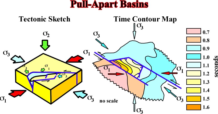
Fig. 194- Pull apart basin are developed in regional extensional tectonic regimes with s1 vertical. However, locally and in association with strike slip faults, local compressional tectonic regimes (with
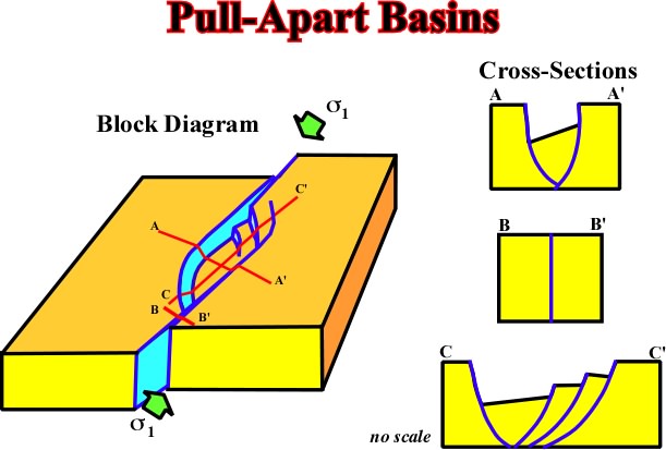
Fig. 195- On this sketch are represented three seismic lines illustrating different geometries found on pull-apart basins,
The deformations associated with the "Maradi fault zone", located southward of Hawasina nappes, in Oman, are typical examples of this kind of deformation as illustrating on the next figures.
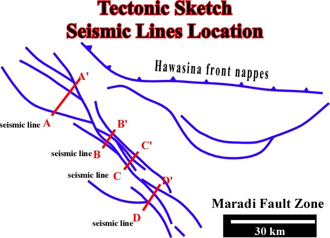
Fig. 196- Location of the seismic lines illustrated in the following figures.
The following seismic lines illustrate the deformations associated with Maradi's fault zone, where pull-apart basins were developed (the lines are located on the previous structural sketch).
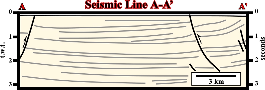
Fig. 197- On this seismic line the shortening is not quite quite evident, since the geometry of the faults seems normal, i.e. the inversions is relatively small.
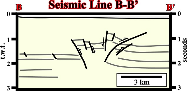
Fig. 198- On this seismic line the shortening is evident. All faults have a reverse geometry, i.e. inversion and reactivation was strongly enough to change the fault geometry.
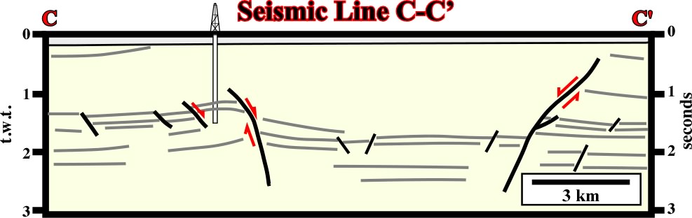
Fig. 199- In spite of the fact thyat locally shortening is evident, one can say that on this line extension is preponderant.
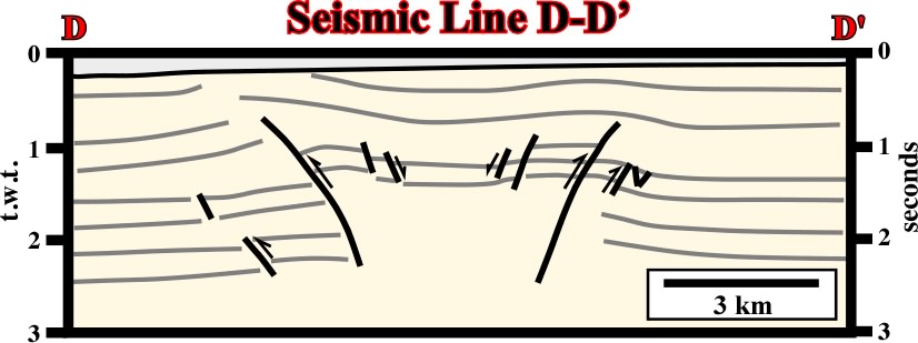
Fig. 200- Here again, inversion was strong enough and so the geometry of faults is predominantly reversal.
5.1.2.2- No Tectonic Stress (
When tectonic stress is nil and
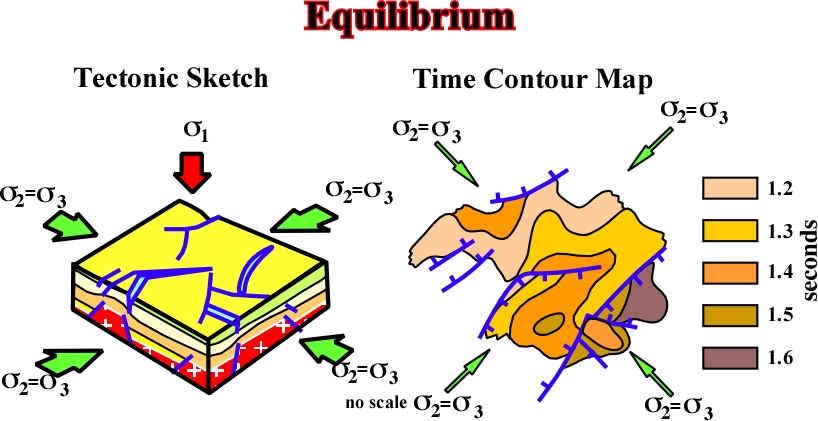
Fig. 201- Generally this tectonic regime, characterized by a
Admiteddly, in this tectonic regime, the sediments are lengthened by:
(i) Normal faults,
(ii) Differential compaction antiformes.
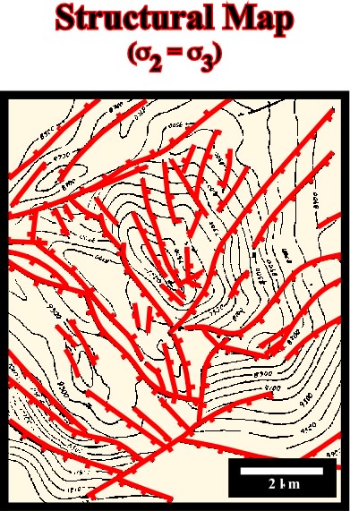
Fig.202- This tectonic regime (
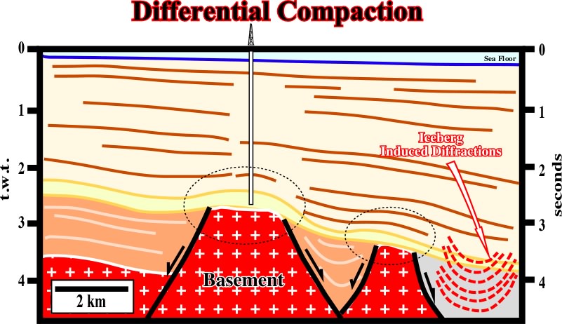
Fig. 203- On this seismic line, the structure tested by drilling correspond to a compaction structure over a high of basement (supracrustal rocks). The sediments of the cover were lengthened by more or less radial faults, which suggests a tectonic regime with a
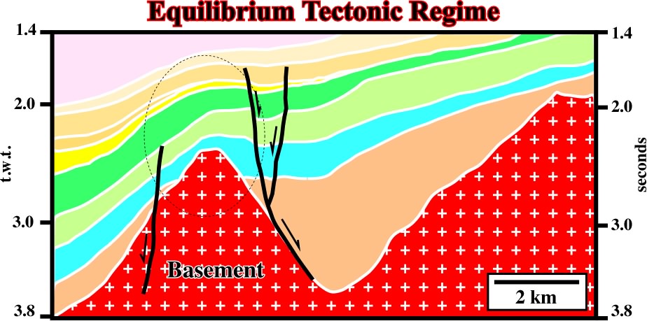
Fig. 204- A local equilibrium tectonic regime, characterized by a vertical s1 and a
5.1.2.3- Negative Tectonic Stress (
When the tectonic stress is negative, the ellipsoid of the effective stresses is triaxial and so the sediments are lengthened by normal faults striking parallel to
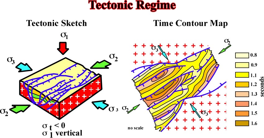
Fig. 205- Sediments can only be lenthened by normal faulting. In addition, when the ellipsoid of effective stresses is triaxial the normal faults strike roughly parallel to the
The structures associated with this tectonic regime are:
a) Rift-type basins and Grabens (fig. 206 to fig. 209),
b) Continental divergent margins,
c) Differential subsidence,
d) Differential uplift and
e) Transfer basins.
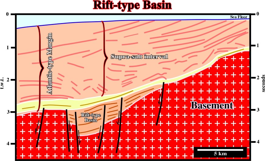
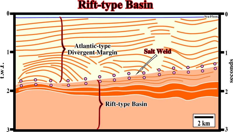
Fig. 206- A rift-type basin is clearly recognized within the basement and below the sediments of the the overlying divergent margin, in which a salt induced tectonic disharmony allows to differentiate supra and infrasalt sediments.
Fig. 207- When the rift-type basin are too big, their half-graben geometry is difficult to recognized as illustrated on this seismic line from offshore Cabinda (Angola). Indeed, below the salt induced tectonic disharmony, the rift-type sediments (the infrasalt sediments of the margin are under seismic resolution) look like those deposited in association with a regional subsidence rather than a differential subsidence.
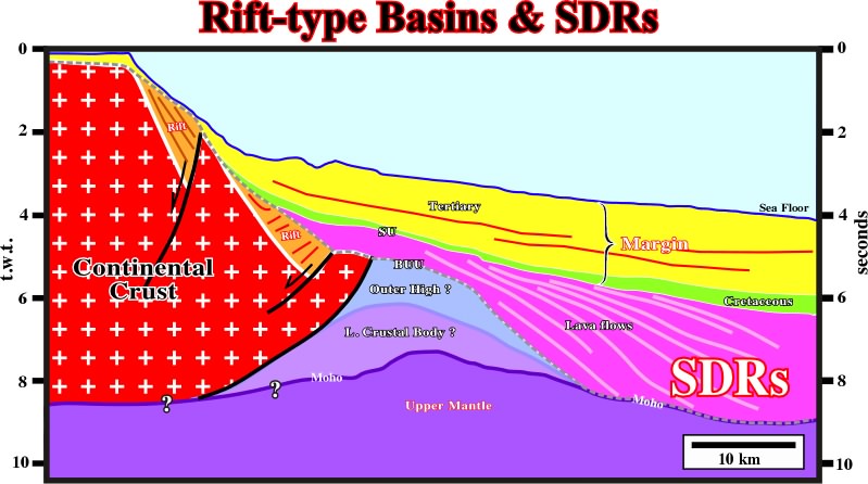
Fig. 208- Generally, the sediments of rift-type basins dip landward contrariwise to the post breakup subaerial lava flows which dip seaward (seaward dipping reflectors or SDRs). In this particular example, coming from offshore Brazil, it is quite easily to reconstruct the original dip of the rift-type sediments (before seaward tilting). In other words, explorationists should not confound the SDRs (without generating petroleum potential) with the sediments of the rift-type basins, which, under certain conditions, can be quite rich in organic matter and so considered as potential source rocks.
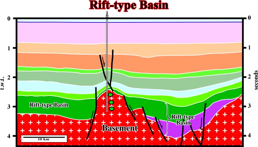
Fig. 209- Structural high points in a rift are not the result of an uplift; they are the less subsident points. In other words, here is not development of horst structures but grabens (maximum of subsidence).
Note that if an extension affects a pre-faulted basement, the pre-existent lineations (faults, weak zones, etc.) can be offset and develop transfer basins, as illustrated below (fig. 210).
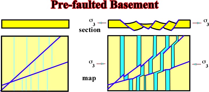
Fig. 210- When an heterogeneous basement is extended, normal faults parallel to
In hydrocarbon exploration, this tectonic regime, which creates tilted blocks should be studied with caution. Actually, the hydrocarbon exploration of tilted blocks is a highly risky when explorationists do not know exactly the location of the potential reservoirs and the lateral seals. Nice examples of such a problem can be illustrated by some oil fields in Gulf of Suez (fig. 211).
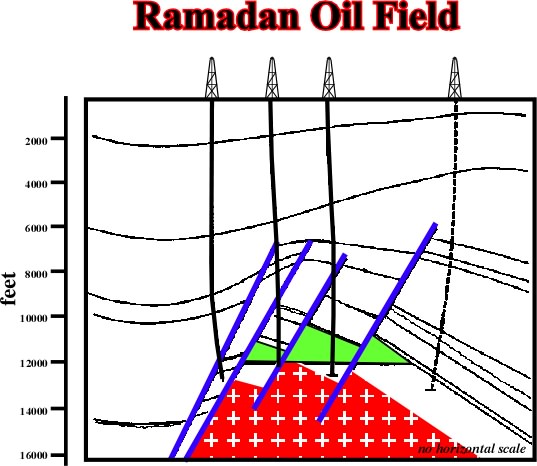
Fig. 211- On this sketch, it is quite evident the dry wells were done before explorationists recognized where the reservoir interval was located. Indeed, when drilling morphological traps by juxtaposition (tilted blocks), the location of the well is dependent of the location of the potential reservoirs intervals.
b) Continental divergent margins
This tectonic regime is mainly found in Atlantic-type continental divergent margin (fig. 212), that is to say, in margins associated with the formation oceanic crust. In other words, with margins outside of the megasutures.
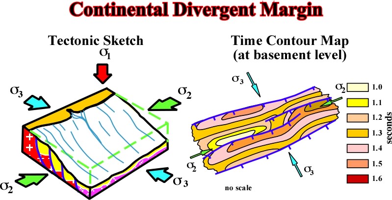
Fig. 212- Overlying rift-type basins, created by a differential subsidence, the margin is developed during a triaxial extensional tectonic regime, in which the
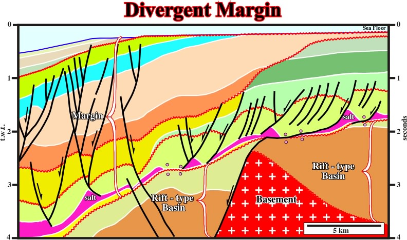
Fig. 213- On this seismic line from the Offshore Angola, there are two major truncations near the outer shelf above the Atlantic Hinge Zone. Across this hinge zone, the base of salt (and base of Tertiary) has a cumulative vertical offset of about 3 s, equivalent to between 3 and 4 km. The deeper truncation is typically assigned to the middle to late Oligocene and is onlapped by Miocene strata. It was formed by up to 30 km landward erosion and 600 to 2000 m of vertical truncation of the Upper Cretaceous and Paleogene carbonate platform (Steckler et al., 1997, Congo; Karner et al. 1997, Gabon). The truncation coincides with a major eustatic fall in relative sea level of more than 300 m at about 30 Ma. But the estimated 2 km of truncation would requires that most of the relative fall in sea level was caused by epeirogenic uplift of the shelf. Note, that the thermal subsidence following continental breakup in the Neocomian would have been largely complete by the Oligocene. Thus, the Atlantic Hinge Zone owes very little to thermal subsidence, only a bit to eustatic changes, and much more to coastal uplift. The cause of this uplift may be connected with uplift above the Cameroon hotspot, which subsequently emplaced the Cameroon Volcanic Line in the Miocene (Meyers et al., 1996). Fluid inclusion temperatures in offshore Angola indicate a thermal pulse in the Miocene which raised temperatures by 30° – 40°C and the geotherm to 50–60°C/km (Walgenwitz, 1990). Temperatures increased northward toward the Cameroon hotspot. Then followed a period of tectonic stability dominated by overall progradation as relative sea level rose to present-day levels. The shallower truncation affects the youngest strata on the outer shelf. The previous slide showed that across a width of at least 15 km on the shelf, Upper Cretaceous isopachous strata have been truncated at the sea floor. This line shows that farther west at the present shelf break, a zone at least 8 km wide contains Neogene foresets that end abruptly at the sea floor; their geometry suggests truncation rather than toplap. Truncation appears to be related to uplift and erosion of the entire Congo coastal plain, which created outcrop belts of successively older, truncated units in a landward direction.
The tectonic evolution of divergent margins proposed by Burchfield (fig. 214) was refuted by the Atlantic seismic lines particularlyin South Atlantic.
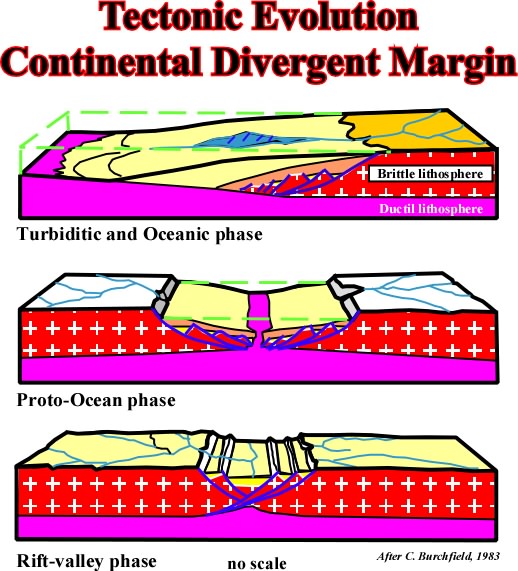
Fig. 214- This hypothesis was often refuted particularly in the timing of the breakup, which, as illustrated in the next figures, seems to take place at the end of the rifting phase and not during an hypothetical proto-ocean phase.
In the South Atlantic, and particularly in the Offshore Angola, the conventional opening hypotheses assume the Aptian salt basins formed before the breakup of Pangea (fig. 215).
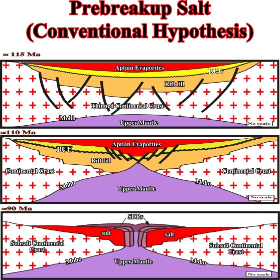
Fig. 215- This hypothesis has several implications: (1) rifting took place both before and after salt deposition; (2) conjugate salt basins were originally a single giant salt basin that was later divided by continental breakup; (3) the breakup unconformity should overlie the Aptian salt, but this is not observed; (4) evaporites were thickest in the center of the giant salt basin, above breakup zone, but this is not observed; (5) after breakup, the oceanward edge of salt basin is abrupt, fault-bounded margin through thickest salt, but this is not observed; (6) basalts should sink into thick distal salt until they froze and strengthened, but this is not observed; (7) seaward-dipping reflectors should overlie distal salt basin, but this is not observed.
We prefer an alternative hypothesis (Total's hypothesis), in which the salt basins formed after the continents separated and sea-floor spreading began (fig. 216).
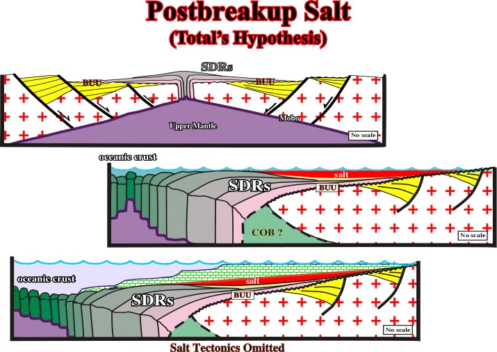
Fig. 216- On this hypothesis: (1) rifting ended before salt deposition; (2) the Aptian salt overlies the break-up unconformity (observed on seismic lines); (3) conjugate salt basins were always separate and independent; (4) oceanward edge of salt basin is a pinch-out of thin salt, which creates a toe-thrust that may be thickened by later salt flow (observed on seismic lines); (5) seaward-dipping reflectors should underlie the distal salt basin or its age equivalent. This is observed wherever seaward-dipping reflectors have been identified.
On a continental divergent margin, differential subsidence is often near the hinge line as illustrated in fig. 217.
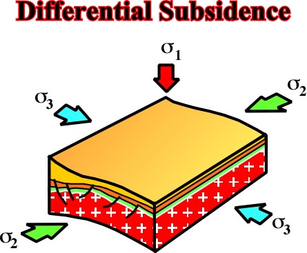
Fig.217- Near the hinge line of a basin, a local extension tectonic regime is often created, which oblige the deposited sediments to lengthen along to s3 forming grabens (not rift-type basins) striking parallel to the hinge line (s2), as illustrated in fig. 218.
The structures developed by differential subsidence are generally associated with the basin hinge lines (fig. 218):
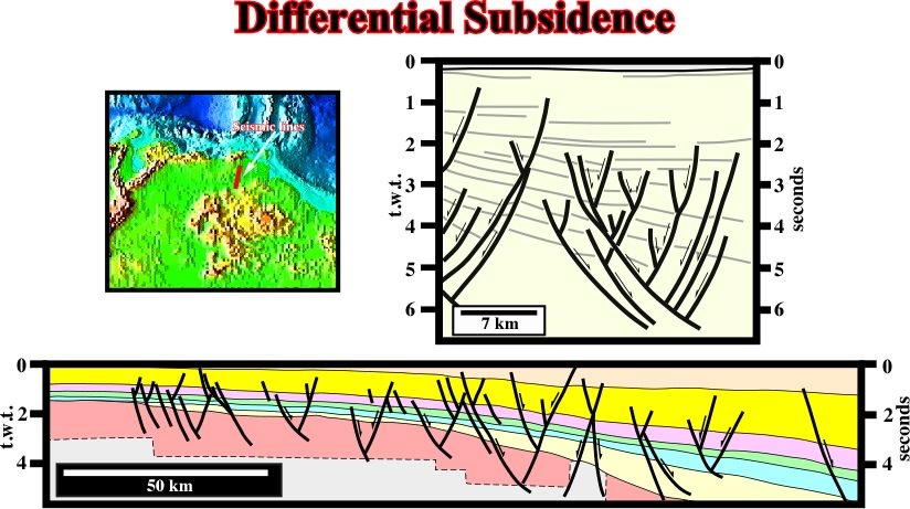
Fig. 218- In onshore Venezuela a lot of oil accumulations are associated with graben striking parallel to the hinge line of the basin. Indeed, around the hinge line, the sediments were lengthened by normal faults, with opposite vergences, developed parallel to the hinge line.
Since E. Argand (1924), the horizontal tectonic stresses became the basis of the modern tectonics.
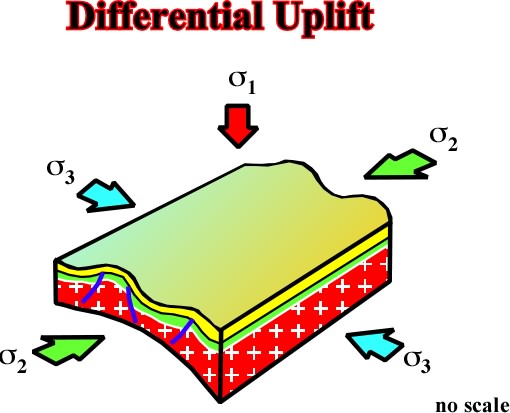
Fig. 219- Vertical movements, i.e., apparent vertical movements are just a consequence of folding and the elementary tectonic feature fault does not mean a special rupture along the earth's radius but a rupture due to the lack of plasticity of a brittle "BATI" under horizontal tectonic stresses. Therefore epirogenic movements can be considered as folds with a very wide wavelength.
Examples of differential uplifts can be seen in the seismic lines of Sevier Desert (central Utah), which has been taken as an example of large scale extensional allochthonous structure (fig. 220).
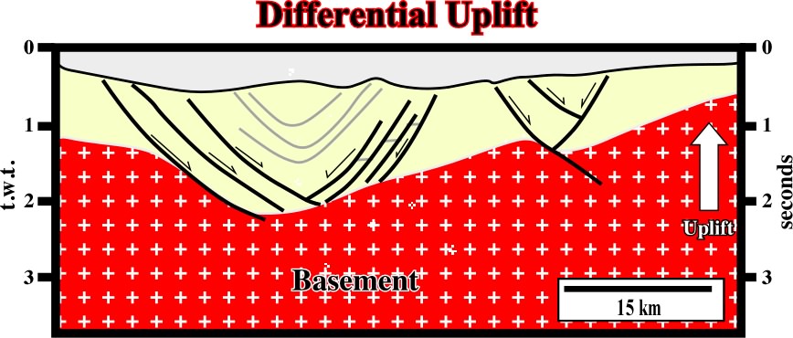
Fig. 220- As illustrated on this seismic line (Sevier Desert), the footwalls may remain unrotated while other parts may rotate in opposite directions over a low-angle normal fault.
As illustrated in the next figures different geometries can be found on the cross-sections of these basins.
![]()
Fig. 221- As said previously, transfer basins are often the result of the extensional reactivation of pre-existent faulted zones. Therefore, they strike obliquely to
![]()
Fig. 222- On this sketch, the section AA' and CC' are located in what one call normal extensional basin (striking parallel to
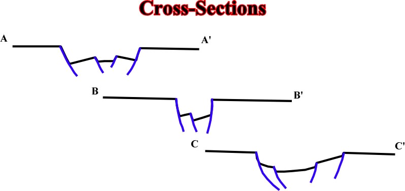
Fig. 223- In spite of the fact that the basins strike in different directions, the cross-sections are quite similar. Subsequently, on a single seismic line (fig. 224) it is quite impossible to differentiate transfer basins from "normal basin" (normal grabens).
![]()
Fig. 224- On this seismic line from the Tanganyika Lake, one cannot say if it corresponds to a transfer basin or to a normal graben. Such a differentiation requires to known how the faults strike in relation to
to continue press here
next
![]()
Send E-mail to ccramez@compuserve.com or cramez@ufp.pt with questions and comments about these notes.
Copyright © 2001 CCramez
Last update: March, 2006