
South Bengal Offshore
Lower Bengal Fan
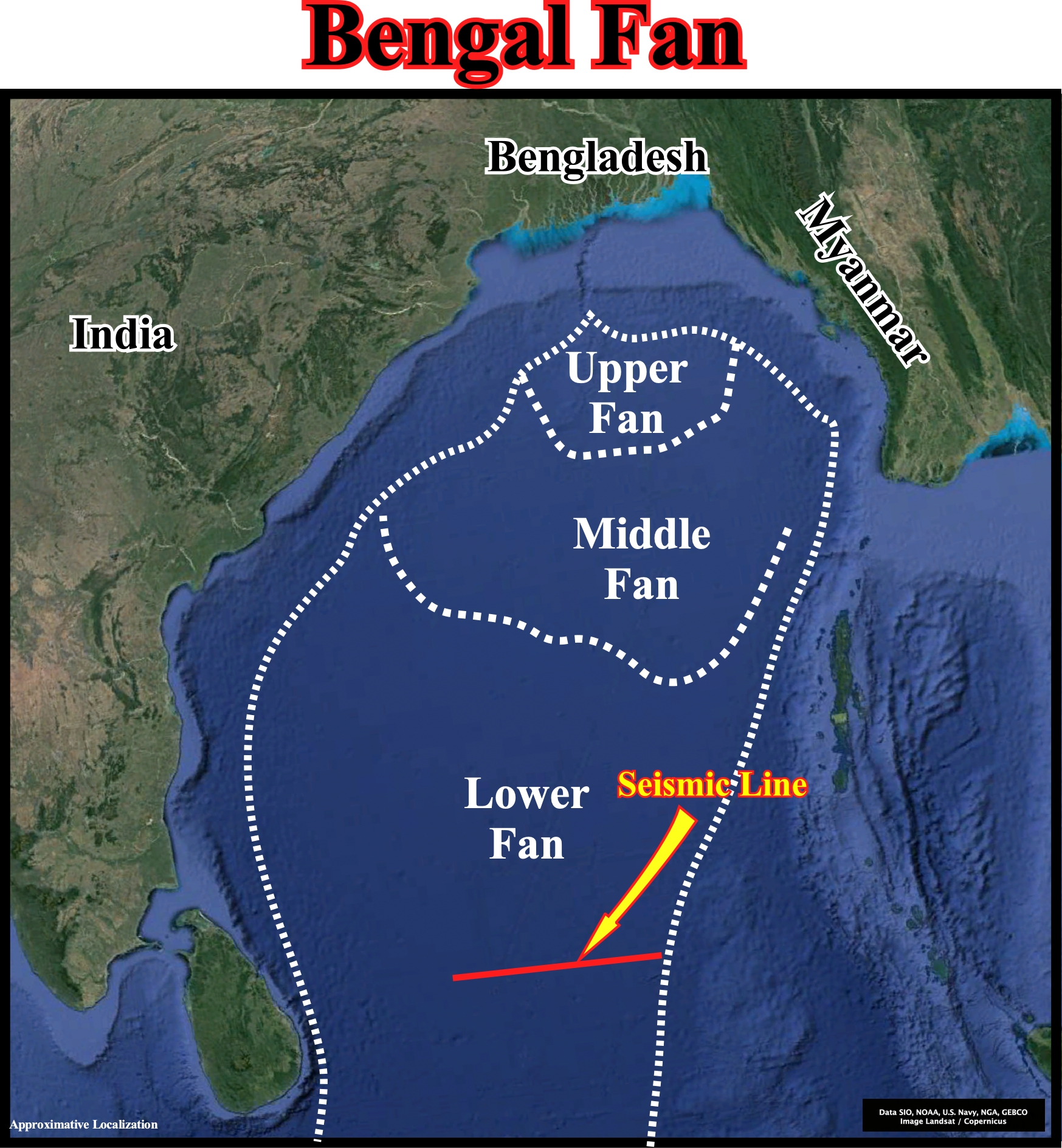
This plate illustrates the approximative extension of the Bengal fan, located between the eastern India offshore, which corresponds to the stacking of rift-type basins and an Atlantic-type divergent margin, and the B-type subduction zone bordering the Burma lithospheric plate. The upper, middle and lower fan are delimited, roughly, as well the location of the next Canvas autotrace, which recognizes, mainly, the lower Bengal fan.
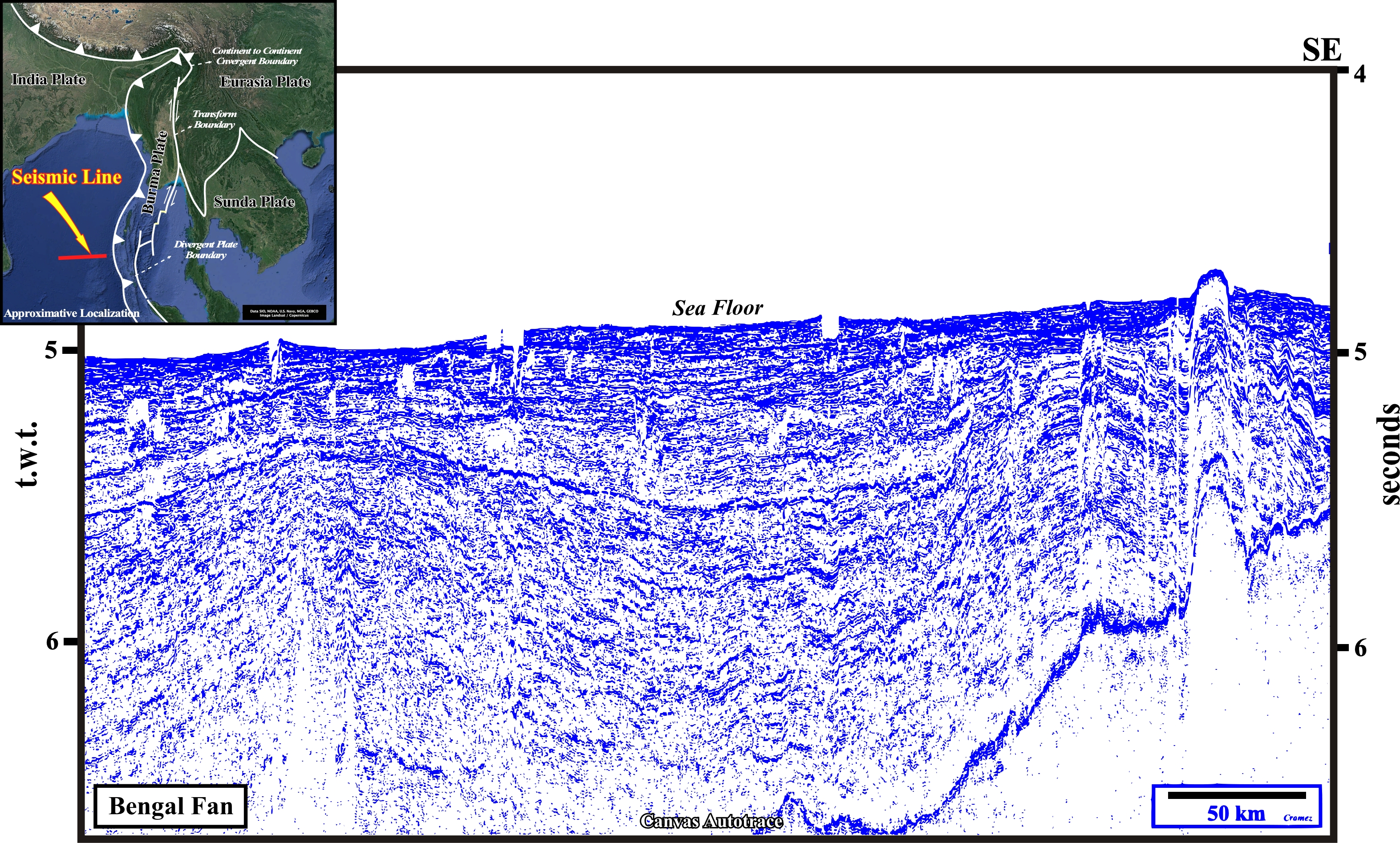
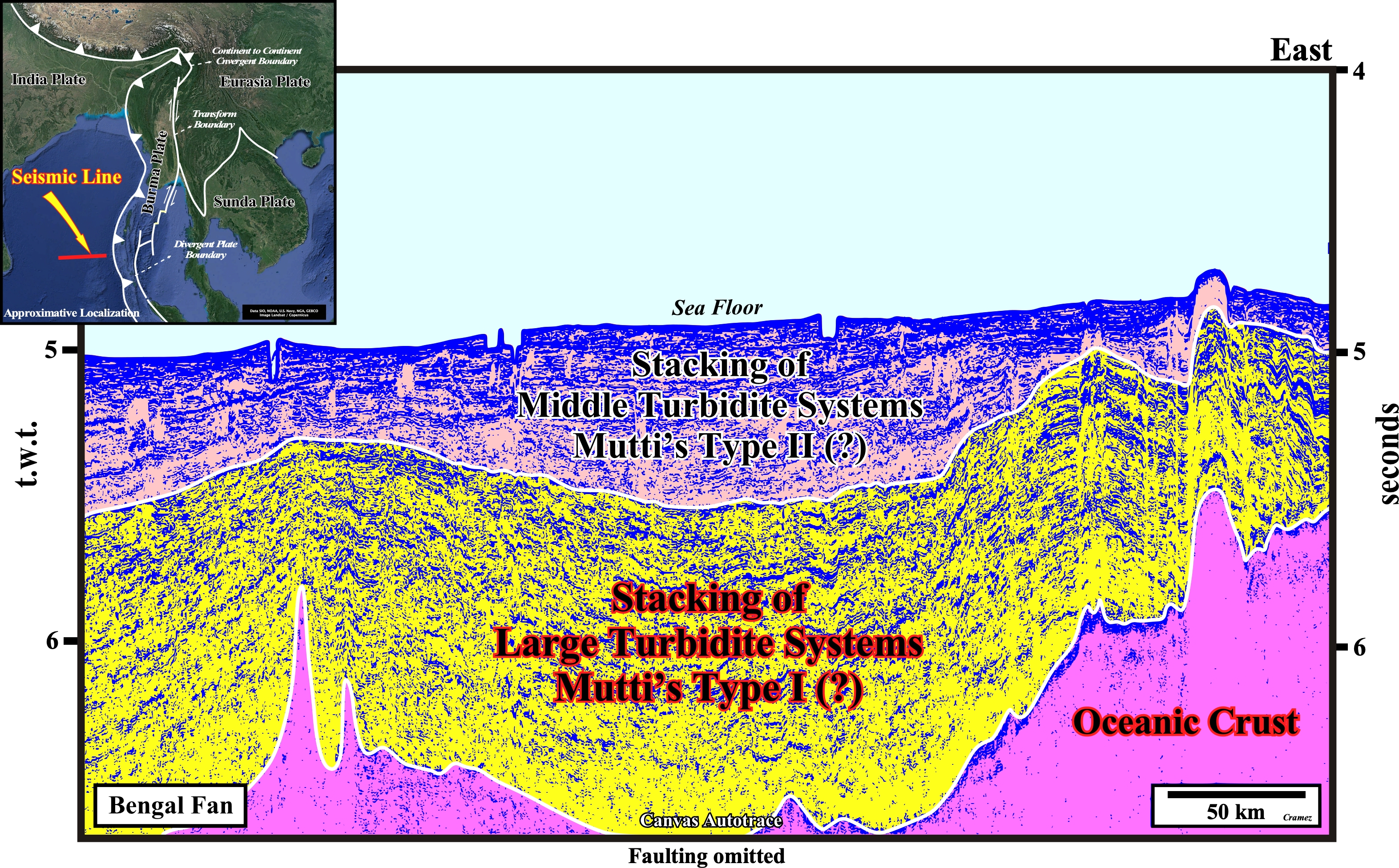
This Canvas autotrace can be tentatively interpreted as composite by three seismic intervals : (i) A basement formed by oceanic crust ; (ii) A stacking of large turbidite systems (Type I in the Mutti's model), which corresponds, roughly, in P. Vail's model to distal submarine basin floor fans and (iii) A stacking of middle turbidite systems (Type II in E. Mutti's model), which in Vail's model correspond, more or less to distal submarine slope fans.
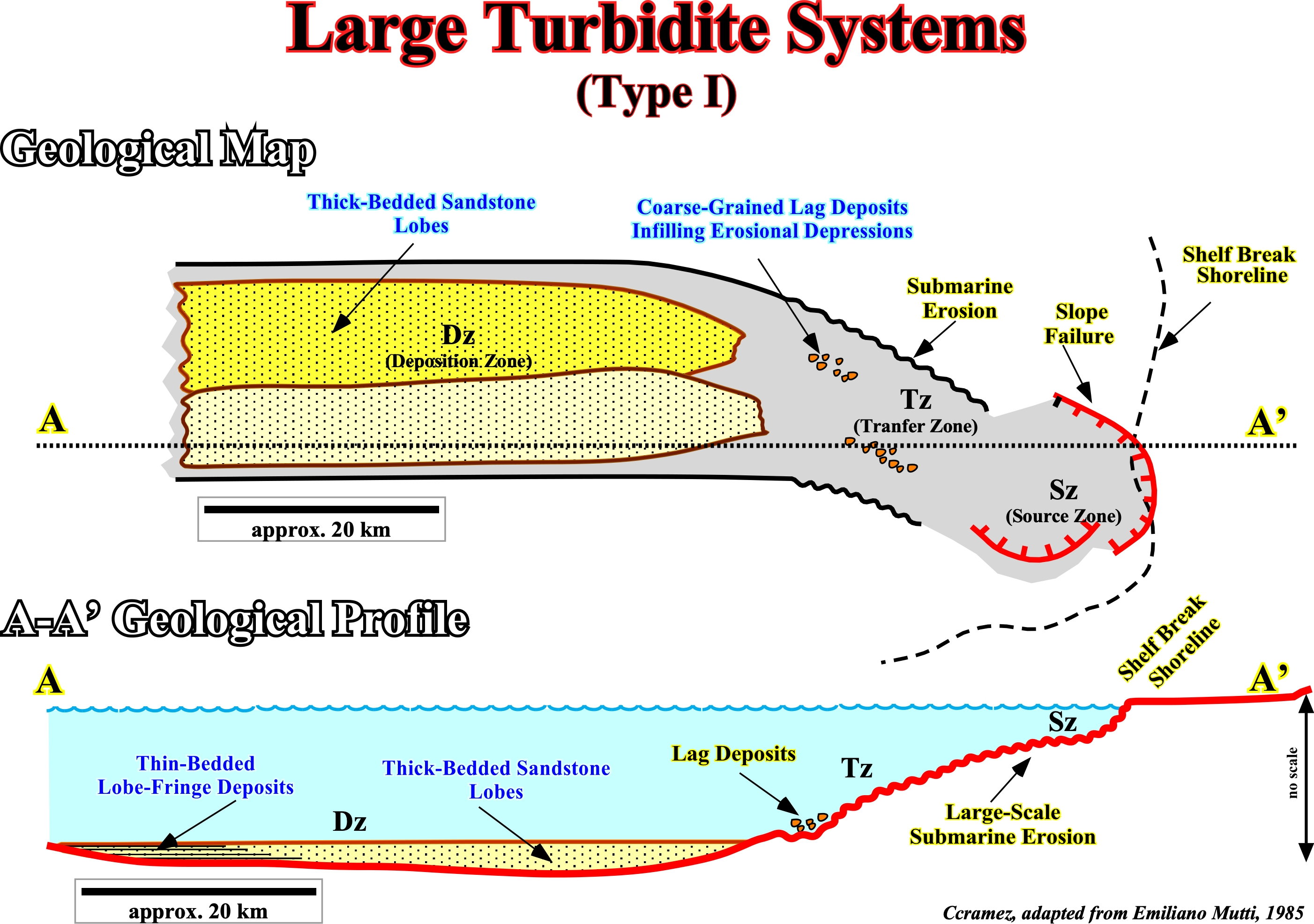
Assuming that the turbidite currents have a high degree of freedom, i. e., in absence of effective obstacles along the slope, the turbidite deposits can be : (i) Large Turbidite Systems ; B) Middle Turbidite Systems, and C) Small Turbidite Systems., based either on the volume and texture of the gravity flow (sand-rich / mud-rich systems or type I, II and III of Mutti, 1985) or linked to the physiography of the margin and predominant sediment granulometry of coastal systems (Reading & Richard, 1994). Such a classification takes into account the "efficiency" concepts of Mutti (1979) and it corresponds to classification that he proposed in1985: (A) Type I, mainly composed of tabular lobes ; -(B) Type II, mainly composed of transition channel-lobes and (C) Type III, composed mainly of channel-levee complexes. Above, it is illustrated the geological model of the Large Turbidite Systems (Type I), which is characterized by a large zone of non-deposition with by residual deposits between the continental slope and the most proximal part of the abyssal plain, and, seaward, thick-bedded sandstone lobes and thin-bedded lobe-fringed deposits. This geological model can make plain and comprehensible the yellow seismic interval of the previous tentative interpretation, in which the following geological features are likely: a) The main depositional zone is located in the abyssal plain ; b) The bulk of sandstones occur in non-channelized and elongated lobes in the outer area of the system ; c) The potential sand-prone reservoirs have a tabular geometry with tens of kilometers of extension ; d) The individual strata thickness range between 0.5 - 2 m ; e) The thickness of each lobe, commonly ranges between 3-15 m thick ; f) The total thickness of each system can reach 50-100 m with a sand/shale ratio (N/G around) of 50% ; g) Each lobe is thick-bedded and grades seaward into thinner bedded and finer grained deposits ; h) They create huge morphologic traps with large four way dip closures, etc.

![]()
![]()
Send E-mails to carlos.cramez@bluewin.ch with comments and suggestions to improve this atlas.
Copyright © 2001 CCramez
Last update:
2022![]()