

15) Trapping (structural & non-structural)
Structural traps are developed in shortened geological structures. They have their own closure (four way dips). Traps against faults do not exist. Few geoscientists know what is a morphological trap by juxtaposition. Hydrodynamic traps in the majority of the cases are, totally, forgotten.
Hydrocarbons can be trapped, in economic quantities, when, in the ground, there are, simultaneously :
(i) An isolated area of a reservoir-rock with low potential (low displacement pressure) and
(ii) A barrier (seaéling-rock) with a displacement pressure strong, enough, to retain the hydrocarbons.
The migration of hydrocarbons whether primary (expulsion of hydrocarbons out of the kerogen and source-rock) or secondary (transfer of oil to areas of lower pressure and temperature) follow the direction of decreasing pressure gradients. Their accumulation will be, preferably, in areas with low potential areas. The displacement pressure of a sealing-rock depends on both the physical character of the seal (pore throat radius and pore throat size distribution) and the physical character of the hydrocarbons (interfacial tension and wettability).
Conventionally and depending on the predominance of the geological factor responsible for the isolation within the reservoir-rock of a lower potential sector, certain geoscientists classify the traps into three broad categories:
A) Structural Traps ;
B) Non-structural traps, which can be:B.1) Stratigraphic ;
B.2) Associated with an unconformity and
B3) Morphologic, which can be morphologic by juxtaposition or just morphologic.C) Hydrodynamic traps.
Structural traps are, in every point of view, a very special and very different type from the other two categories of traps. Their closure, i.e., the barrier that forces the flow of hydrocarbons to accumulate upstream, is, fundamentally, different from the closure of non-structural and hydrodynamic traps. This difference is very significant not only geometrically, but also at the dynamic point of view.
At geometrical point of view, the closure of structural traps is formed by a chronostratigraphic concave downward geometry of the layer forming the cover. This characterizes all traps associated with anticlines. Obviously, such a definition does not apply to the traps associated with non-synchronous warped surfaces of the sand-prone sedimentary anomalies that are very recognizable on seismic lines. Also, it cannot be applied to the reef structures, which are typical morphological traps.
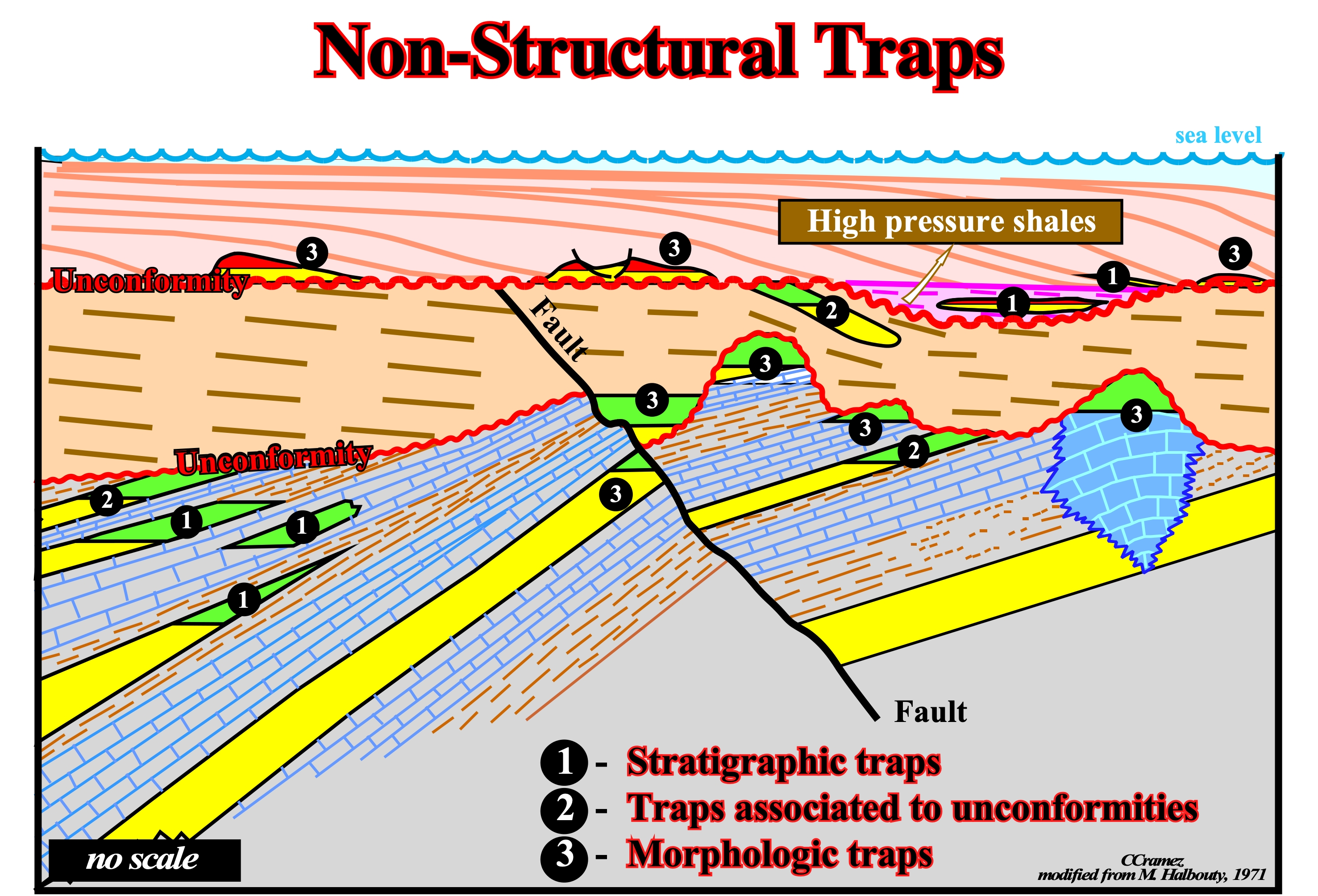
Figure 064- On this idealised cross-section all types of non-structural traps, i.e., stratigraphic traps, traps associated to unconformities and morphologic traps, are depicted. It interesting to notice they are the result of a contiguous presence of a reservoir-rock and a sealing-rock, i..e, very closed or connected in space or time.
At the dynamic point of view, the difference between the closure of structural traps and the others types of trapping is even more pronounced. A closure is a barrier to hydrocarbon migration, i.e., a passage from a porous and permeable facies (lithology) to a fine grained sediment with a pore or displacement pressure greater than the pressure exerted from the outside fluids. If the capillary pressure is sufficient to force the oil-water interface through the pores of the upstream sediments, they do not form a barrier to hydrocarbon migration.
In structural traps the flow of hydrocarbons is perpendicular to the bedding, while in the other traps, the flow is parallel. The trapping associated to faults, i.e., where a fault is, directly or indirectly, associated with trapping, is completely different of the structural traps, since the flow of the hydrocarbons is not perpendicular to the layers.
Structural traps, due to their geometry, are very easy to highlight and their closures are much more effective. In fact, if the first layer above the reservoir-rock does not have a displacement pressure strong enough to trap the hydrocarbons, there is always a likelihood that a higher stratigraphic levels owns a higher pressure to trap them.
Non-structural traps, are more difficult to recognize. They are, often, very obscure and their recognition on the seismic lines is, often, quite subtle. Their closure is, essentially, constituted by the displacement pressure of stratigraphic levels or fractures extending the reservoir-rock. Just one thin bed more detritical, i.e., having a lower displacement pressure, is enough to allow migration of oil or gas.
The aquifers and hydrodynamism play a very important role in the efficiency of the closures. This is, particularly, true for the closures of the non-structural traps, because in these traps, the hydrodynamic gradient is parallel to the layers or fractures and, therefore, parallel to the directions of the preferential leak of the hydrocarbons.
Closures, as well as, covers, under certain pressures and temperatures, are effective to some fluids and not to others. They form a delicate and complex set of inputs and outputs of oil and certain geoscientists think that in most cases, a trap is filled as it is fed upstream at a rate, more or less, equal to that of the losses downstream. The traps, located in the more subsiding sectors of a sedimentary basin, have more chances to be full than those located in stable or uplifted sectors.
Before continuing, we will summarize what all geoscientists have learned about this in petroleum geology courses:
1) Almost all of HC accumulations are associated with an aquifer environment.
1.1 - The interstitial water contained in reservoir-rocks is, generally, in movement.
1.2 - The interstitial water moves toward the areas of low potential (low pressure).
1.3 - The velocity of displacement varies with the difference in potential and transmissibility of the aquifer.
1.4 - The velocity of displacement is, generally, low (few centimeters per year).
1.5 - Hydrodynamism plays a very important role in the movement and trapping the hydrocarbons.2) The gas and oil are immiscible in water and have a lower density.
3) The age, origin, composition and petrophysical characteristics of the reservoir-rocks are highly variable.
4) Potential traps are induced either by tectonics or deposition or by a combination of both.
5) A gradient of the water potential in a reservoir-rock can be a barrier to the movement of hydrocarbons and be a factor of trapping. This is particularly true when it is combined with tectonic and stratigraphic factors.
6) The shape and size of the pores, the permeability pathways and the chemical composition of reservoir-rocks vary greatly. It is in these pores and chemical environments that migration and trapping takes place.
7) The minimum time for the HC be generated, migrate and be trapped is probably less than 1 million years.
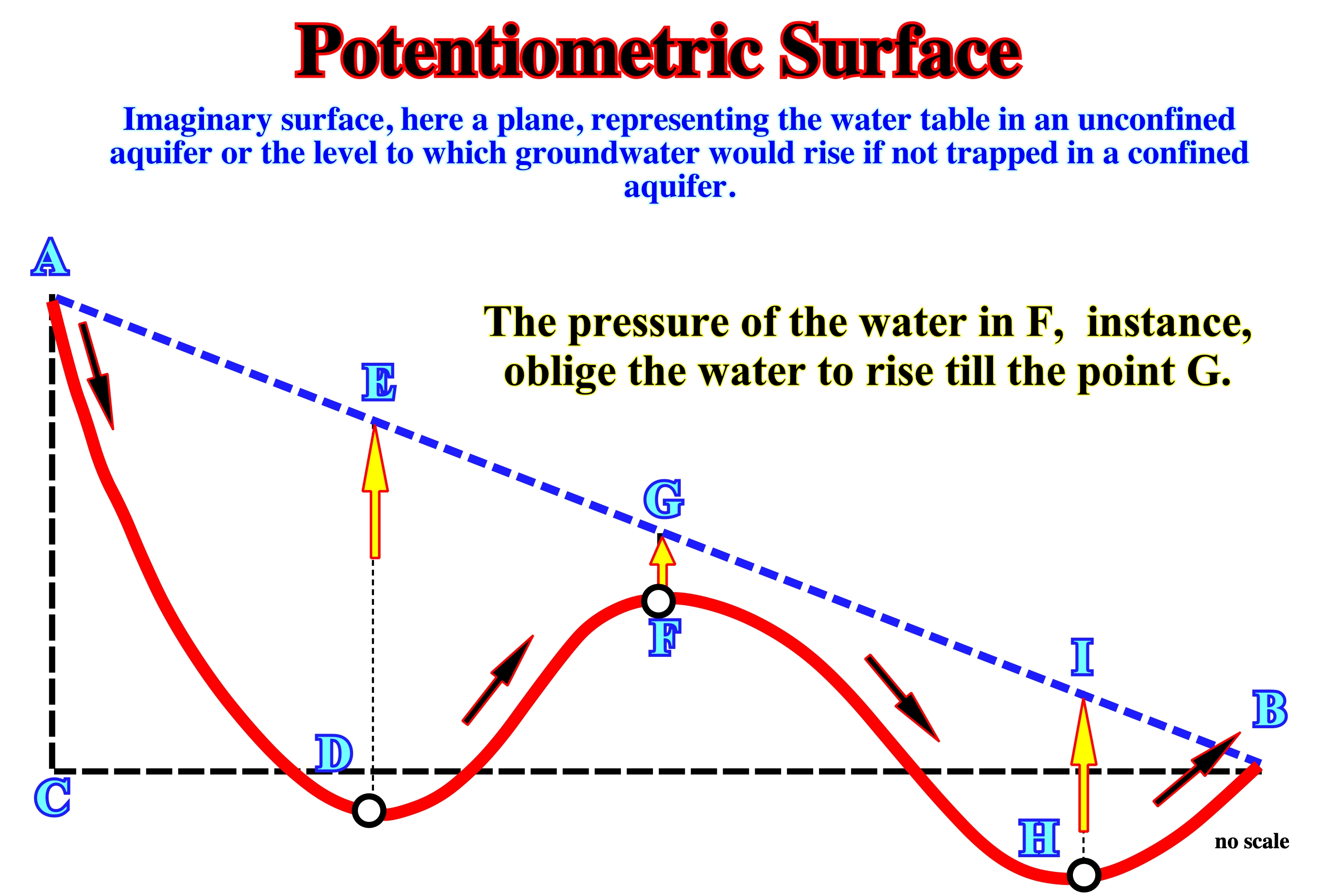
Figure 065 - A potentiometric surface is an imaginary surface, here a plane, representing the water table in an unconfined aquifer or the level to which groundwater would rise if not trapped in a confined aquifer. In other words, having two storage tanks of water with one full and one empty will gradually fill / drain to the same level, since the full storage tanks has a great enough potentiometric surface to provide flowing water toward the empty one. Groundwater level measurements can provide important information about local groundwater resources. Because differences in water-level elevation provide potential for flow, spatial mapping of water-level elevations can permit the identification of regional groundwater flow direction. In general, the potentiometric surface for a water table map follows the overlying land-surface topography and intersects the land surface at major streams, lakes, or wetlands.
8) The upper and lateral boundaries of a trap whether structural, stratigraphic or both and with or without hydrodynamic component is a surface, relatively, impermeable and concave downward.
9) The temperatures of the reservoir-rocks range between 50° and 160° C.
10) The fluid pressures in the reservoir-rocks can vary in time. They increase or decrease depending on the geological evolution.
11) The history of the traps is very variable. It can be associated to a single geological episode, or to a combination of events spanning in significant geological periods.
12) If oil or gas contained in the water that is expelled from the shales into the reservoir-rocks (primary migration) it must displace the water already present, which creates a movement of the water toward potential issues.
13) The HC particles entrained by the moving water moving along reservoir-rocks tend to flocculate in the form of small droplets, which are transported with water until their sizes are large enough so that their buoyancy can develop a movement independent of the water.
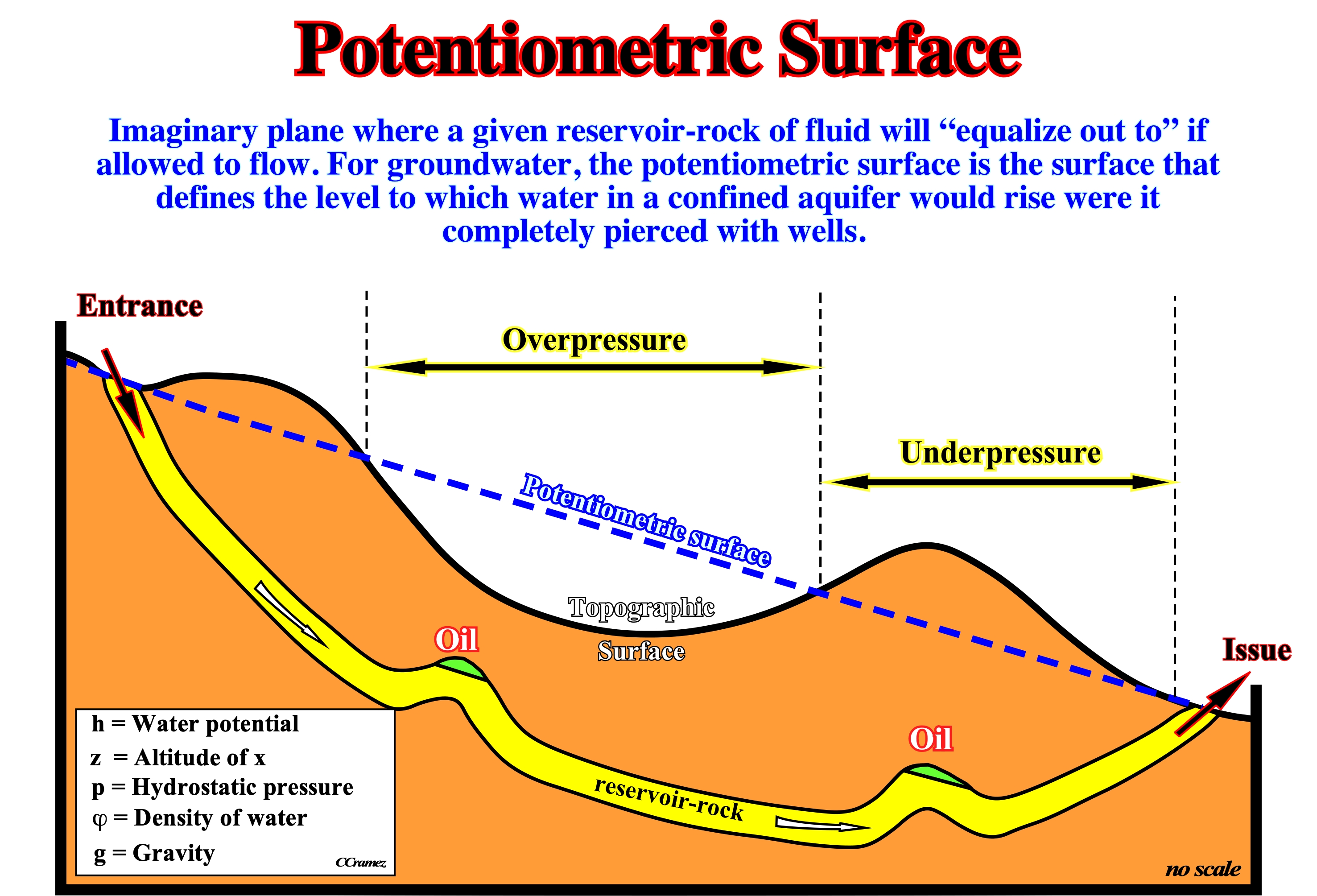
Figure 066 - The potentiometric surface, is the hypothetical surface, in blue, which represents the level to which groundwater would rise if not trapped in a confined aquifer (an aquifer in which the water is under pressure because of an impermeable layer above it that keeps it from seeking its level). The potentiometric surface is equivalent to the water table in an unconfined aquifer. In the area of over-pressure, artesian wells are likely,i.e., the well sunk through impermeable strata into strata receiving water from an area at a higher altitude than that of the well, so that there is sufficient pressure to force water to flow upwards, what is not the case in the underpressure sector. Due to the shortening of the sediments, the reservoir-rock, in yellow, was locally uplifted, which induced a global downdip flow of the aquifer (from the entrance till the issue), which tilted the oil-water plane contacts. Such a tilting is observed in the majority of the oil accumulations of the sedimentary basins developed in association with the megasutures as, it is the case, of the back-arc basins. The examples of the geographic Neuquén basin corroborate such a conjecture.
14) In the movement of water inside a reservoir-rock geoscientists must take into account two pressure gradients :
(i) The hydrostatic pressure gradient increased by water pressure depth due to the weight of the overlying water column and
(ii) The hydrodynamic pressure gradient, i.e., the gradient of the potential existing in the aquifer, in which the water moves.
- If the potentiometric surface of an aquifer is horizontal, the system is in equilibrium hydrostatic and the water formation is not moving.
- If the potentiometric surface of an aquifer is inclined, the system is in equilibrium hydrodynamic and the water is in motion.
15) The movement of the water in the reservoir-rocks changes, continuously, according to the variation of pressure gradients.
16) The altitude of the potentiometric surface, in a given point, can be calculated from the density of water and the pressure of the reservoir:
h = z + p / φg
where,
“h” is water potential,
“z” the altitude of x,
“p” the hydrostatic pressure,
“φ” the density of water and
“g” the gravity.17) When the potentiometric surface intersect or overlap a trap, the pressure of the reservoir-rock is atmospheric and hydrocarbons float in water. (figure 067)
Returning to the closure’s problems, one can say aquifers and hydrodynamism play a very important role in the effectiveness of closures. Their influence is particularly true for the closures of the non-structural traps because the hydrodynamic gradient, as said previously, is parallel to the beds or faults, i.e., parallel to the directions of preferential hydrocarbons escape (leaking).
In the evaluation of a trap, it is important and, often decisive, to know whether there are hydrodynamism (movement of liquids and the movement of solids in a liquid) and if it is in the direction of the flow of oil or the opposite. The consequences are not the same. In young subsiding sedimentary basins, such as the cratonic basin of the North Sea or Atlantic-type margins divergent, most of the sedimentary series still are in the process of compaction. The highest hydraulic potential is located in the central and deeper parts of the basin. Consequently the hydrodynamic gradients are mostly centrifugal.
In sedimentary basins associated with the Mesozoic / Cenozoic megasuture, such as the SE Asia or South America episutural basins (backarc basins) or the perisutural basins (foredeeps), which are, generally, under compression, the structural deformations uplift and fold the sediments :
- These deformations are, generally, most pronounced along the ancient normal faults bordering basement highs and near the margins.
- The deepest parts of these basins, with very high hydraulic potential, are, often, inverted as a result of sedimentary shortening becoming high structural areas.
- The deepest parts of these basins, with very high hydraulic potential, are, often, inverted as a result of sedimentary shortening becoming high structural areas.
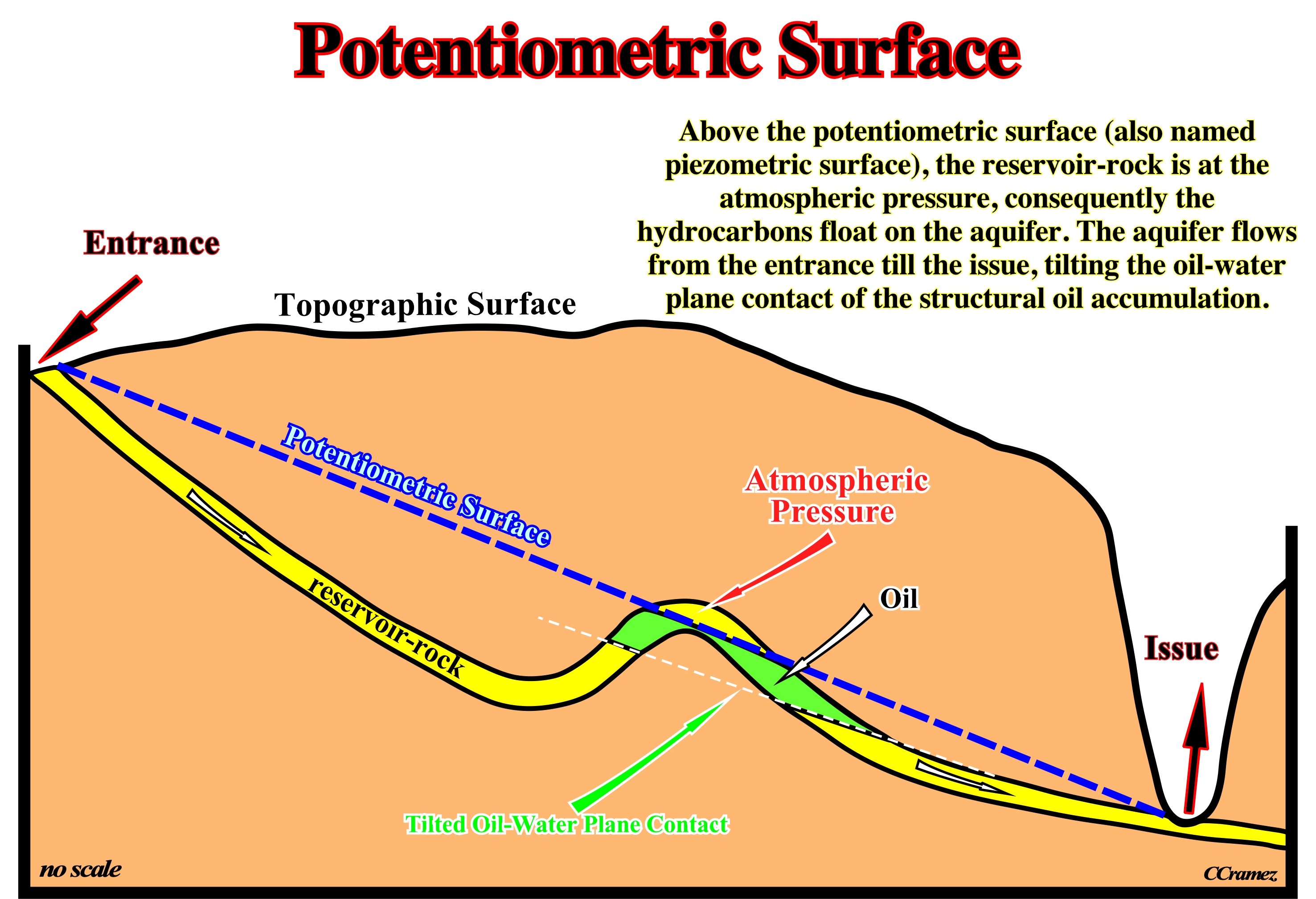
Figure 067- In this sketch, obviously, above the potentiometric surface (also named piezometric surface), the reservoir-rock is at the atmospheric pressure, consequently the hydrocarbons float on the aquifer. The aquifer flows from the entrance till the issue, tilting the oil-water plane contact of the structural oil accumulation. As most hydrocarbons are lighter than water, they migrate, often, upward through adjacent rock layers until either reaching the surface or becoming trapped within reservoir-rocks by impermeable rocks above. However, the process is influenced by underground water flows, causing oil to migrate hundreds of kilometers horizontally or even short distances downward before becoming trapped in a reservoir. The reservoir pore-fluid pressure is a fraction of the overburden pressure that is supported by the fluid system. The other portion is supported by the rock and generates the in-situ rock stress. The overburden pressure is created by the weight of the rocks composing the lithostatic column at the point of observation. Hence, the difference between the overburden pressure and the vertical rock stress can approximate the pore pressure. Notice that the potentiometric surface of a confined aquifer is not a flat surface. It shows high areas and low areas just like the hills and valleys found on land. Just as surface water tends to flow downhill, groundwater tends to move down-gradient from water-table areas (or potentiometric regions) of higher elevation to water-table areas (or potentiometric regions) of lower elevation.
In the evaluation of the non-structural traps, geoscientists must do not forget :
If the flow of the aquifer is in the same direction as that of hydrocarbons, it will decrease the efficiency of the closure and eventually there will be no trapping (figure 068).
To trap hydrocarbons under such conditions particular geological factors must be present. The migration being in the direction of decreasing pressure gradients, most likely, all hydrocarbons migrated along the unconformity (figure 068), to areas with lower potential (a higher oil accumulation or to the surface).
However, if the reservoir-rock is protected by an overlying layer with a very high pressure, this layer may be an effective cover and it is possible that hydrocarbon remain trapped in the reservoir-rock. Nevertheless, the accumulation will be profitable just if :
(i) The hydrodynamism is not to active and
(ii) The structural behavior of the reservoir-rock is, more or less, horizontal.
On this subject, it is interest to point out that certain oil fields, as for instance, the Gabian oil field, located in South France, had the particularity of deflate very quickly. Despite that, every spring, after the winter rains, the production restarts. The meteoric water causes a local increasing of centripetal hydrodynamic flows, which prevented the oil to disperse. Migrating toward the surface, it is trapped by hydrodynamism.

Figure 068 - The top left sketch shows the negative influence of a hydrodynamic flow (arrow direction) along the hydrocarbon migration direction. There are no trapping in onlaps of the reservoir-rock (yellow) or in the faulted blocks. The top right sketch shows the favorable influence of a hydrodynamic flow in opposite direction to the migration of hydrocarbons. There are often trapping in the onlap reservoir-rock termination and in the footwall of the faulted block. In the lower sketch, is illustrated the influence of aquifer flowing downward in a structural trap (anticline). The wall of the accumulation, i.e., the water-oil plane contact is dipping in the direction of flow according to the Hubbert’s law : t.g.Φ = dh /dx x dw /(dw- dh).
In structural traps, the influence of hydrodynamic gradient is much less marked. The flow of the aquifer, which is parallel to the bedding planes, can just displace laterally the hydrocarbon accumulation as illustrated in figure 068. The wall of accumulation, i.e., the water oil plane contact is inclined according to the Hubbert’s law (1953) : t.g.Φ = dh /dx x dw/(dw- dh), in which
“Φ” represents the angle of the oil-water plan contact with the horizontal,
“dh / dx,” is the slope of the hydraulic tectonic nappe (see figure 068),
“dw” the density of water and
“dh” the density of the hydrocarbons.
According to Hubbert’s equation, it is evident the tilting of the oil-water plane increases with inasmuch the hydrodynamic gradient is stronger and the densities of oil and water are closer and nearer 1.
When the hydrodynamic flow is very important, the hydrocarbon accumulation can be completely swept out of the trap. In such conditions, in these kind of traps, it can happen that the hydrocarbon column exceeds the theoretical closure, determined from the structural maps. It is therefore important to distinguish:
(i) The theoretical closure (determined from geological data, mainly from seismic and field data) and
(ii) The impregnated closure or practice closure, is that given by the actual height impregnated in the volume of the trap.
In structural traps, for mono-layers accumulation (a single bed of reservoir-rock), the impregnated closure can be:
(1) Equal to the theoretical closure (in this case, geoscientists say that the reservoir has a fill factor of 1)
(2) Less than the theoretical closure (in this case, the load factor is less than 1).
For multi-layer accumulations (several beds of reservoir-rocks), geoscientists should considered:
(a) If there is a unique water-plane contact (the impregnated height is then equal to the structural closure) or
(b) If there are different wear-plane contacts (the total height is greater than the largest structural closure).In other words, in the evaluation of a structural trap, geoscientists must necessarily take a position on these possibilities and use the more likely. In some cases, the prospect may not interest the economists, but in others, it may be economically profitable.
In non-structural traps of some episutural or perisutural basins, in which the hydrodynamic gradients are, often, centripetal and opposite to the hydrocarbon migration, geoscientists noticed, with satisfaction, that the impregnated oil column exceeded, sometimes a lot, the theoretical closure determined from seismic data or calculated by the formula Hobson (1954):
Zc = 2y (rt /rp) / g (rw-rh), where
“Zc” is the right of the oil column ;
“y” is the interfacial tension (the necessary work necessary per unit area to expand the interface between two immiscible fluids, in this case the water and oil) ;
“rt" corresponds to the radius to the tubules between the pores ;
“rp" is the radius of the pores assumed equal to that of the oil drops ;
“g” the gravity force ;
“rw" the water pressure and
“rh" the oil pressure.
All this was corroborated by a lot of oil fields, what obliged geoscientists to recognize the importance of hydrodynamic conditions in the exploration of non-structural traps. In fact, most of the non-structural traps provide economically viable deposits, just if the hydrodynamic conditions are favorable. Otherwise, the accumulations will rarely exceed the geological success.
In onshore Argentina, and particularly, in the backarc basins, which have been shortened and are, often, overlain by foredeep basins, down-dip hydrodynamic flows are quite common. Such a flows, opposite to the migration of the hydrocarbon, strongly favor the trapping mechanism as it is the case, for instance, of the Aguada Pichana field32, illustrated in figure 069.
32Aguada Pichana field is a gas field located in the Neuquén basin. This field discovered in 1971 by YPF was evaluated, until 1980, for 25 wells without be put into production. In 1993, it was proposed to Total Austral, as part of the compensation on the price of gas from the geographic Cuenca Austral. In 1994, after the assessment and acceptance of the offer of YPF, Total Austral, became operator. Since then, more than twenty development wells, located between the appraisal wells were drilled in order to start production in early 1996 field.
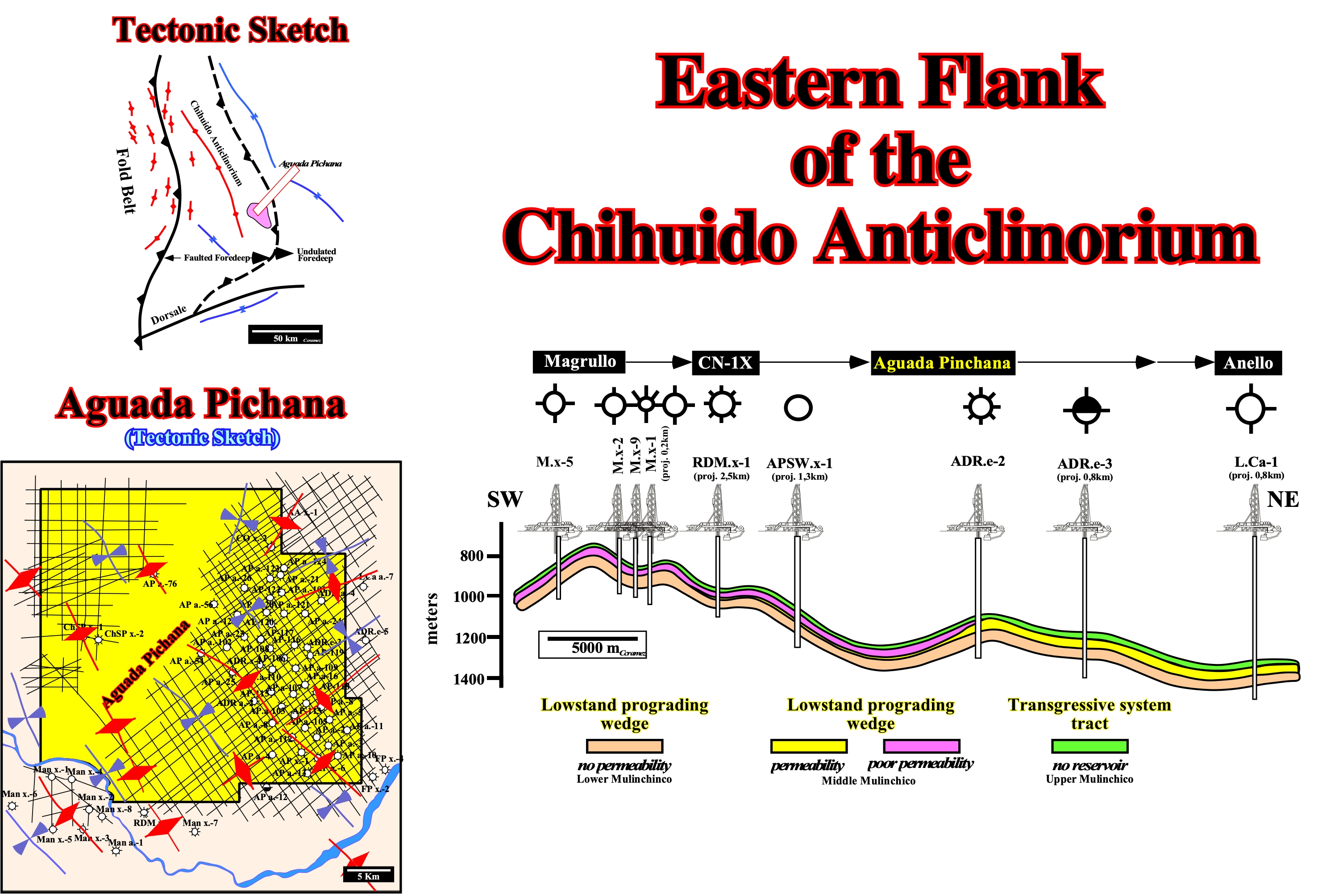
Figure 069 - Locally, Aguada Pichana field is located on the Eastern flank of the Chihuido anticlinorium on the south of an anticline structure. This schematic geological section, illustrated on this figure underlines the Easter flank of the Chiuido anticlinorium. The final structuration of the Neocomian clastic sediments seems polyphasic and the characteristic distribution of the reservoir-rocks aleatorious. The cartography of the structural axes deducted from the seismic map of the top of the Middle Mulinchinco formation strongly suggests a polyphasic deformation with two different axial directions (NW-SE and NE-SW). The chronology of these shortening, which, so far, was not yet established, is fundamental for the understanding of the trapping and evaluation of the remnant hydrocarbon potential. On the other hand, the hydrodynamic trapping component seems evident, just noticing the location of the hydrocarbon and the dry well. Indeed, the majority of the dry wells seem to be in the highest structural points. The hydrocarbon accumulations to have been displaced eastward in the sense of the hydrodynamic flow of the aquifer.
The hydrodynamism can also affect the reservoir-rock characteristics. In fact, in Aguada Pichana field, the reservoir quality is directly related to a necrosis induced by a significant diagenesis (formation of clay minerals and silica) which seems to have occurred during the burial and uplift reservoir rocks. Everything seems to indicate that approximately 30 x 106 years ago, the potential reservoirs (sandstones of the Middle Mulinchico formation) had been buried till depths of 3500 meters. Thereafter, during the Andean orogeny, these horizons have been raised and are now, in the area of Aguada Pichana field, at a depth of about 1,500 meters. During this burial and then during the uplift, the chemistry of hydrodynamic currents (centrifugal initially and, thereafter, centripetal) and the changes in pressure and temperature have profoundly changed the petrophysical characteristics of the potential reservoirs.
The classification of the traps proposed above (figure 064) is the Halbouty's classification, which is the one that is best applied to the hydrocarbon exploration. It is particularly useful in evaluating the petroleum potential of residual oil basins.
This classification distinguishes two large families :
A) The structural traps and
B) Non-structural traps.A - Structural Traps
- By definition, these traps are formed after the deposition of sediments.
- They are characterized by a concave downward geometry of the couple reservoir sealing-rocks.
- The reservoir-rock and cover are, in most cases, are composed by a single depositional system ; between the reservoir and the cover does not exist any major geological event, such, for instance a tectonically enhanced unconformity.
-These traps represent about 90% of the giant oil fields in the world (a giant oil field must have at least 70 million tons of reserves, i.e., more or less, 500 Mbbl, while a gas field must have at least about 70 Mm3, around 2.5 TCF)
As examples of these traps the following fields are often cited :
a) Romachkino, in the Urals-Volga, which has a closed area of about 3000 km2.
b) Samotlor, in Western Siberia, which has a closed area of about 2000 km2.
c) Ghawar, in Saudi Arabia, which has a structural closure of about 2300 km2.
d) Kirkuk, in Iraq, in the foothills of the Zagros, has reserves that exceed 2000 Mt.
e) Kangan, in Iran, which has gas reserves of several hundreds of TCF.
f) Gasharan, Iran, whose reserves exceed 1600 Mt.
g) El Furrial, Venezuela, in the Maturin basin, which has reserves in excess of 4 G barrels.
h) El Carito in Venezuela, which is the western extension of Furrial field.
i) Cusiana, in Colombia, etc.B - Non-Structural Traps
The non-structural traps (figure 056) represent, currently, about 10% of giant fields in the world. This low percentage should be weighted by the importance of the Middle East fields, which in its vast majority are associated with structural traps, and by difficulty of their recognition. Today, these traps are in all petroleum exploration programs. Many geoscientists think that that the majority of the reserves to discover are related to non-structural traps.
Most of the economically profitable non-structural accumulations result from the interaction of various trapping parameters. Mr. Halbouty subdivided them into three subfamilies according to the predominant factor in geological trapping :
B. 1 - Stratigraphic traps sensu stricto ;
B. 2 - Traps associated with unconformities, mainly with tectonically enhanced unconformities and
B. 3 - Morphologic traps.B. 1 - Stratigraphic traps
- Stratigraphic traps are basically the result of facies changes that take place during or after deposition.
- When the trap is synchronous with the deposition, one can distinguish :(i) The lateral facies change from permeable to impermeable and
(ii) The pinch-out of reservoir-rocks.The lateral termination of a reservoir-rock can be done by proximal, distal, marine or coastal onlaps.
- As examples of the first ones (i) the following fields can be cited:
- Candeias, in the Reconcavo Basin, Brazil ;
- Bell Creek, in the Powder River Basin, Montana.
- Jay, in the onshore Alabama-Florida (USA), etc,- As example of the second ones (ii) the fields following fields are, often, cited :
- Bolivar, Venezuela (Lake Maracaibo and vicinity), whose reserves exceed 15 G bl ;
- Quiriquiri, Venezuela (1 G bl) ;
- Pembina, Canada (2 G bl), etc.B. 2 - Traps associated with Unconformities
- The traps associated with unconformities (figure 064) are formed when an impermeable layer (clay, salt, etc.), which is the cover of the trap, fossilizes an erosional surface and is in direct contact with a reservoir-rock in localized under the unconformity.
- The filling of these traps, that is to say, the migration is mostly “per descensum” directly from the source-rock, which plays, also, as a cover.
- A “per ascensum” migration is always possible, but it is rarer.
- These traps are associated, preferably, with tectonically enhanced unconformities, more or less flattened (peneplain) by erosive agents (angular unconformity).
- They are easily differentiated morphological traps located below the erosion surfaces, that is to say, from the buried hills.
- As these traps are the direct result of stratigraphic cycles, they are present in all petroleum basins
- Their recognition requires fine stratigraphic analyses, in particular, sequential analysis. These analyses, either made using the seismic, land or subsurface data, must always start from stratigraphic cycles associated with eustatic cycles of the first order, to those of lower order.
- Their approach, like that of any exploration, is, generally, done from the general to the particular and not the opposite. When the hierarchy of stratigraphic cycles is not respected in a sequential analysis leads to failure, i.e., lithological predictions are false.
- The size of the hydrocarbon accumulations associated with these traps varies from a few hundred to several millions recoverable barrels.Some examples:
- East Texas (> 5 G bl, USA) ; - Prudhoe Bay (> 10 G bl, Alaska) ;
- Hassi Messaoud (> 20 G bl, Algeria) ; - Meillon (Aquitaine) ;
- Boscan (> 5 G bl, Venezuela) ; - Kevin Sunburst (Montana), etc.B.3 - Morphologic Traps
- Geoscientists speak in morphological traps when topographic feature or sedimentary anomalies are fossilized by overlying sediments, generally, younger and impermeable (figure 056).
- Such anomalies are generally associated with unconformities or with their down-dip correlable conformities and they are produced by geomorphic processes (cuestas) or depositional processes (reefs, turbidite mounds, etc).
- The traps induced by the relative movements of faulted blocks are called morphological by juxtaposition.(i) Their genesis is very different, but the trapping mechanism and their recognition are very similar.
(ii) The throw of the faults (normal reverse) can induce "false topographic anomalies" which, when closed by juxtaposition, form traps with a geometry similar to morphologic trapsAs example of morphological traps the following oil fields can be cited :
- Poza Rica (reefs, in Mexico) ; - Faja d'Oro (reefs, in Mexico) ;
- Redwater (reefs, in Canada) ; - Scurry (atoll, in Texas) ;
- Frigg (basin floor fans, in North Sea) ; - Balder (Basin floor fans, in North Sea) ;
- Marlin & Albacora (Basin floor fans, Campos offshore, in Brazil) ;
- President Aleman (filled canyon, Faja d'Oro, in Mexico).As examples of morphologic traps by juxtaposition, the following fields are often cited :
- Jourdan (Texas) ; - Oklahoma City (USA) ; Sari (Libya) ;
- Bibi Eibat (Russia) ; - Faud (Oman), etc.
A large number of geoscientists, particularly, in South America, continue to take antiform structures as structural traps, even if they were developed by an extensional tectonic regime (σ1 horizontal), i.e., even when the sediments have been lengthened by normal faults. The traps associated with antiforms are typically morphological traps by juxtaposition, in which the movement of the normal fault blocks can put a sealing rock in juxtaposition to a reservoir-rock. Antiforms developed by compression are called anticlines. They shortened the sediments (as the reverse faults), and so they cannot have coeval normal faults associated. In geology, it is impossible to short and to length the sediments at same time in the same place. A lot of geoscientists reserve the term antiform to the shape-bell structures induced by an extensional tectonic regimen and anticline to the structure induced by a compressional tectonic regime.
In reality, when a geoscientist does not recognize normal faults on the apex of an extensional antiform structure, is not because the faults are not present, but just because the throw of the faults is under the seismic resolution (too small to be recognized on the seismic lines). Such erroneous trapping, i.e., take a morphological by juxtaposition traps as a structural traps is, undeniably, the responsible of a large number of unsuccessful wildcats all around the world and particularly in South America.
In fact, when a geoscientist propose a trap (structural or not) he is referring the trapping of a specific reservoir-rock (it is possible that several reservoirs form multiple traps). At the geological and petroleum point of view, proposing traps without specifying the reservoir-rock is meaningless. This is, particularly true, and frequent when, a geoscientist points on a maps a huge antiform structure at the level of tectonically enhanced unconformity (angular unconformity) and thereafter, said that the more likely potential reservoir-rock underlies the unconformity.
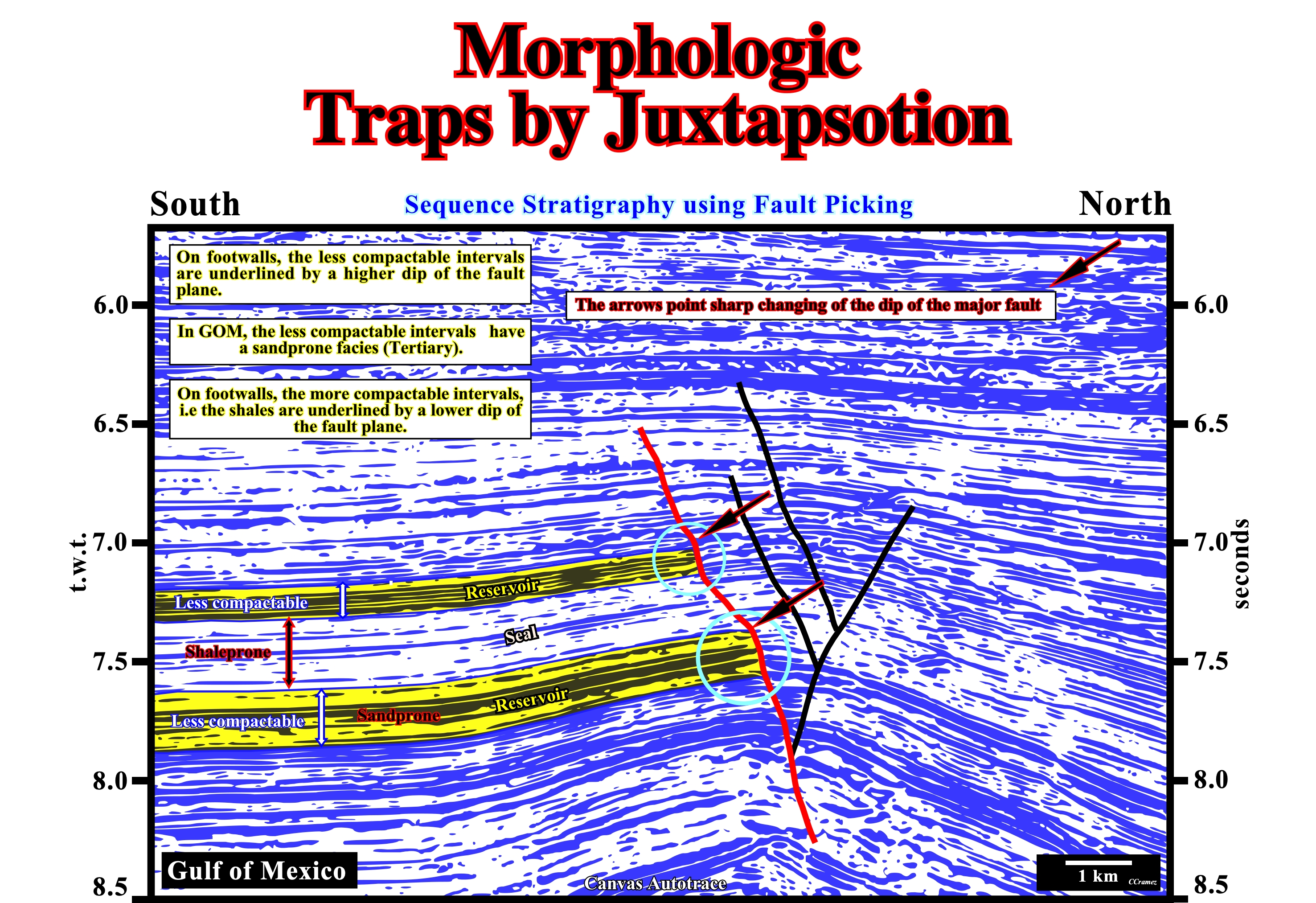
Figure 070 - The antiform structure recognized on this seismic line (Canvas autotrace) is, obviously, the result of the lengthening of the sediments induced by an extensional tectonic regime (σ1 vertical). The normal faults, which allowed the lengthening are clearly recognized on the apex of the structure. The fault planes (mental construction of the geoscientist, since there are no seismic reflections associated) have a quite particular geometry. The dip of the fault plane changes with the lithological changes within of the faulted blocks, particularly the changes in the footwall. Indeed, the dip is much higher is the less compactable intervals, which often correspond to potential reservoir-rocks. In the shale intervals, which are much more compactable the dip of the fault planes is smaller (far from the verticality). Every time the relative movement of the faulted blocks put a less compactable interval (potential reservoir-rock) in juxtaposition with a more compactable interval (potential sealing-rock) a morphological traps by juxtaposition is formed. Consequently, in an antiform extensional structure there several potential morphologic traps by juxtaposition. However, it is evident, that if one of these potential traps contains hydrocarbons, it does not means than the other traps are, also, filled with hydrocarbons. The opposite is also true. Admittedly, to define such a morphological traps it is obvious several geological maps are required : (i) The structural map of the top of the reservoir-rock ; (ii) Isopach map of the reservoir-rock ; (iii) Structural map of the top of the sealing-rock ; (iv) Isopach map of the sealing-rock ; (v) Map of the throw of the fault at each reservoir-rock level.
Each time a geoscientist propose trap, at a given a stratigraphic level (reservoir-rock), the only map that is really significant is the structural map at the top of this level. On the other hand, it should be remembered that there is no trap if there is no cover. The mapping of the cover (lateral and vertical) is part of the geological data needed to define a trap. In the case of non-structural traps, the mapping of the cover is as important, if not more important than the mapping of the reservoir-rock. This is particularly true in morphological traps by juxtaposition, as those illustrated in figure 070.
Downay (1980) long ago, insisted that the trap "against fault" of the certain geoscientists is a misnomer. A fault, which in the field or on a seismic line is just a geoscientist’s mental construction (taking into account very few exceptions, generally, on the seismic lines there are no seismic reflections associated to the fault planes), never traps. Most often, what traps is :
(i) The sediments located on the other side of the fault in juxtaposing to the potential reservoir-rock, or
(ii) The sediments of the gouge zone, if they a present, what is not always the case.
For that, the capillary displacement pressure of the sediments juxtaposed to the reservoir-rock must be greater than greater than that of the reservoir-rock.