
In certain sedimentary basins, in order to avoid misleading interpretation of fault planes, the recognition of reflected refractions is of paramount importance, as in the North Sea (Plate 73). The reflected refractions are often straight lines arrivals. As illustrated below (Plates 74-76), the slope of a reflected refraction is dependent on the velocity of the refractor and its dip. Discontinuities in the refractor can be a departure of reflected refractions (straight lines).
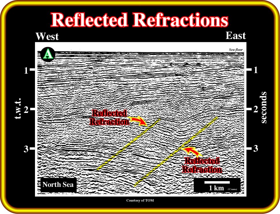
Plate 73- On this migrated line, reflected refraction are it is quite evident in association with a normal fault affecting the refractor bed, which, in this particular example, corresponds to a major unconformity. Generally, in unmigrated lines, a reflected refraction is tangent to the byckward diffraction hyperbola associated with the fault. On the side of the forward hyperbola, the refractor does not exist at the same level. Probably, that explains why on this migrated line, we just see the reflected refraction dipping westward.
The reflected refraction will be tangential to the diffraction at the critical distance:
- Larger amplitudes can be expected in the neighborhood of the critical distance ;
Reflected refractions can appear only on the backward-direction hyperbola. In the forward direction, the refractor does not exist. Still another fault arrival is a simple reflection from a fault plane. It is necessary that the elastic properties of the two rocks separated by the fault differ sufficiently strongly.
- For the fault reflection to be traced very far, the contrast must be maintained along the fault ;
- If this is not met, the fault-plane reflection will vary so much in amplitude and character that the continuity will be impaired ;
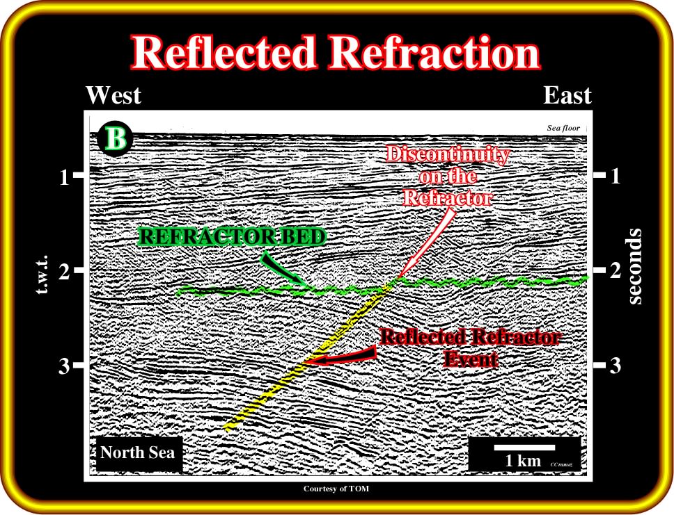
Plate 74- Note the refractor marker in green and the discontinuity (vertical displacement of the refractor marker, i.e., a normal fault), which creates an obvious reflected refraction. The slope of a reflected refraction (in yellow) is function of the velocity of the refractor, that is to say , the velocity of seismic waves along the refractor(in green) and of its dip.
Some fault plane reflections are so persistent in continuity and so regular in character even while cutting a great thickness of varied sediments, that one is led to the conclusion that the fault-plane itself has lithological characteristics, which contrast strongly with those of the enclosing rocks:
(i) Fault plane between sediments and basement rocks ;
(ii) Fault plane injected by intrusive rocks ;
(iii) Fault gouge (soft, uncemented pulverized clay or claylike material, commonly a mixture of minerals in finely divided form, found along some faults or between walls of a fault, and filling or partilally filling a fault zone, R. Bates & J. A. Jackson, 1980) water-saturated or gas-cut ;
(iv) Fault plane filled with sandstone dykes ;
(v) Fault plane with mineralized veins ;
(vi) Fault plane with salt (“fault weld”), etc.
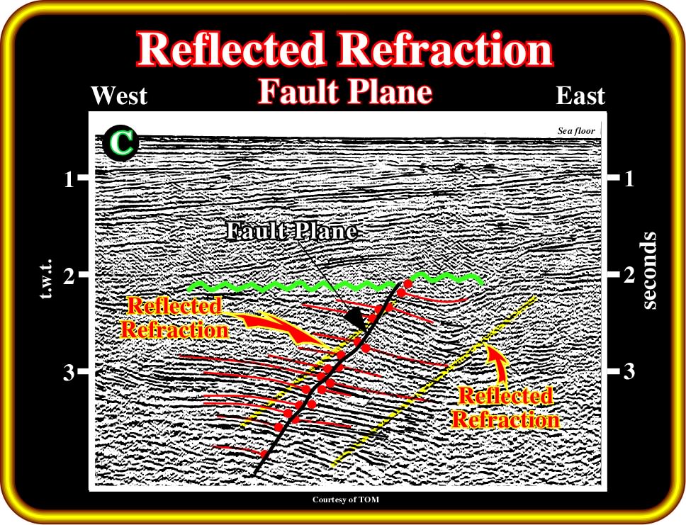
Plate 75- Here, one can see the differences between a reflected refraction and the fault plane of the normal fault affecting the Mesozoic rift-type sediments of the North Sea. As depicted above, the reflected refraction (yellow) is rectilinear downward. Its slope is function of the compressional wave velocity of the refractor bed, that is to say, the higher the velocity of the refractor bed (in green) the higher the slope of the reflected refraction. On the contrary, as pictured, the normal fault plane (in black), emphasized by the reflections termination (red circles), shows changes in dip and its hade slightly increases with depth, since the compressional wave velocity of the sediments increases with depth. The dip changes of the fault plane are associated with lithological changes in the faulted blocks.
In normal geological conditions, there are not primary seismic reflections associated with the fault planes. In practice, the picking of a fault plane, on a seismic line, obeys certain interpretations rules, since a fault corresponds to a more or less abrupt discontinuity of sedimentary layers along which appreciable displacement has taken place.
a) The first step to fault picking is to locate the reflection terminations that emphasize the geometry of the fault plane (Plate 75) ;
b) As illustrated above, the geometry of a fault plane, in the ground or on seismic lines, in general, is not rectilinear:
- The dip of the fault plane changes along its plane as a function of rheologic behavior and compaction of the sedimentary layers ;
- Such irregular geometry contrasts with the rectilinear geometry of the reflected refraction, in which the dip of the reflection emphasizes the velocity of the refractor bed ;
- Reflected refractions and fault planes, recognized on North Sea seismic lines, are illustrated on Plate 74 and 75 ;
- In addition, as a seismic line is a time section, it is physically impossible to have a fault geometry rectilinear.
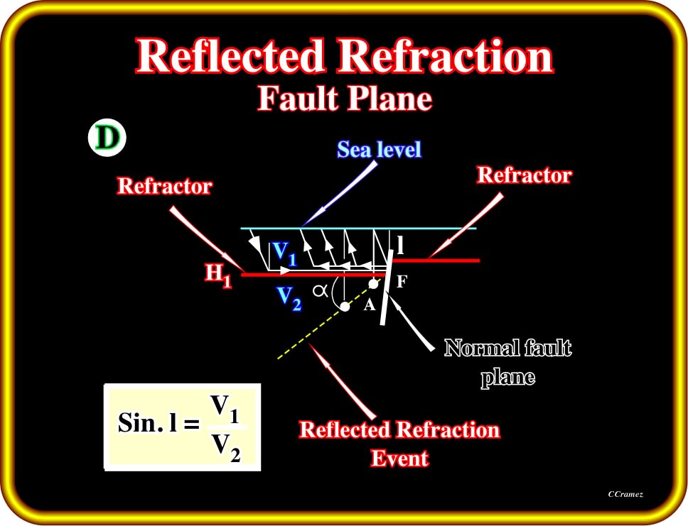
Plate 76- The theoretical principle of the development of reflected refractions are illustrated above. Basically, the seismic waves arriving to the refractor bed H1 (in red) are refracted along it until finding the discontinuity created by the normal fault F. Arriving at the discontinuity poin (normal fault), the waves are reflected backward along the refractor and upwards till the receiver. Subsequently, on a seismic line, the reflected refractor event will be depicted as a more or less continuous rectilinear reflection (yellow) dips toward the hangingwall of the normal fault. The dip of the reflected refracted event is a function of the velocity of the refractor.
Plate 76 illustrates what happen when the reflector is a strong one, with a positive reflection coefficient (i.e. when a low velocity rock overlies a high velocity rock):
- As the observation point moves further from the fault, the angle of the direct path from the diffracting point to the reflector eventually falls below the critical angle ;
- At this distance there are two arrivals ;
- The direct one is a wide-angle diffraction ;
- The second is a reflected refraction-refracted in the high velocity rock, reflected from the fault face.
to continue press
![]()