
Universidade Fernando Pessoa
Porto, Portugal
Seismic-Sequential Stratigraphy
External Forms & Internal Configurations
The overall geometry of a stratigraphic, or seismic unit, consists of the external form and the internal reflection configuration of the unit. Both must be described to understand the geometric interrelation and depositional setting of the units.
Initial analysis always starts in the two-dimensional mode of a single seismic section, and these apparent configurations are later corroborated in a three-dimensional grid of seismic sections. Single sections obviously may cut strata geometry at any angle. However, on these notes, diagrammatical sections illustrating reflections configuration, and seismic lines, are assumed to be parallel with sedimentary dip unless otherwise indicated.
Strata filling negative geologic features in the underlying sediments define characteristic reflection configurations. Underlying reflections may show either erosional truncation or concordance on the basal surface of the fill unit. Fill units may be classified by:
a) External Form
- Channel fill
- Trough fill
- Basin fill
- Front slope fill
b) Internal Configuration
- Onlap
- Mounded onlap
- Divergent
- Prograding
- Complex
- Chaotic
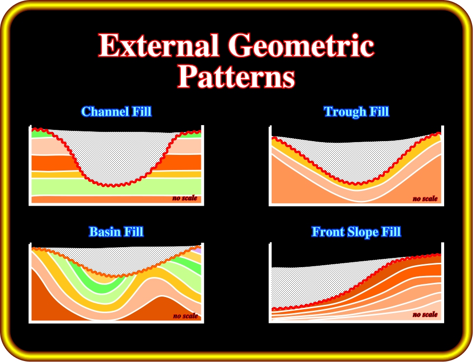
Plate 212- Taking into account the form of infilling units, geologists usually consider, as illustrated above, the following major patterns: (i) channel fill, (ii) trough fill, (iii) basin fill and (iv) front slope fill.
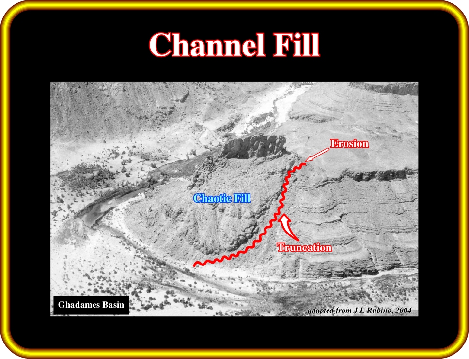
Plate 213 - On this photograph, taking into account the external geometric patterns (truncation), one can recognize a channel fill. Similarly, as we will see soon, the internal filling configuration can be considered as chaotic. It is relevant here to point out that the erosional surface as well as the filling are glacially controlled.
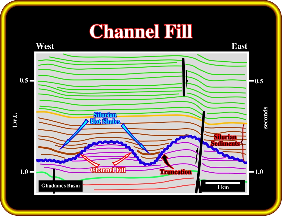
Plate 214 - On this seismic line, channel fill patterns are easily recognized by the obvious truncation reflection terminations of the Ordovician sediments. Similar to the previous slide, the erosion inducing the channel fill geometry is glacially controlled. Later, during the Silurian transgression, these glacial channels were partially filled in onlap by Silurian hot shales, which are by far the best source-rock in the basin.
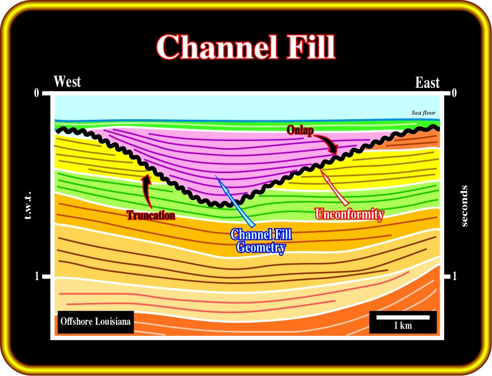
Plate 215 - On this line from offshore Louisiana, a relative sea level fall shifted the coastal onlaps basinward and downward. Subaerial erosion took place on the outcropping shelf creating an erosional surface (unconformity) with a typical channel fill geometry. Later, when relative sea level rose, the negative morphologic feature were onlapped by a slightly divergent shaly interval (channel fill).
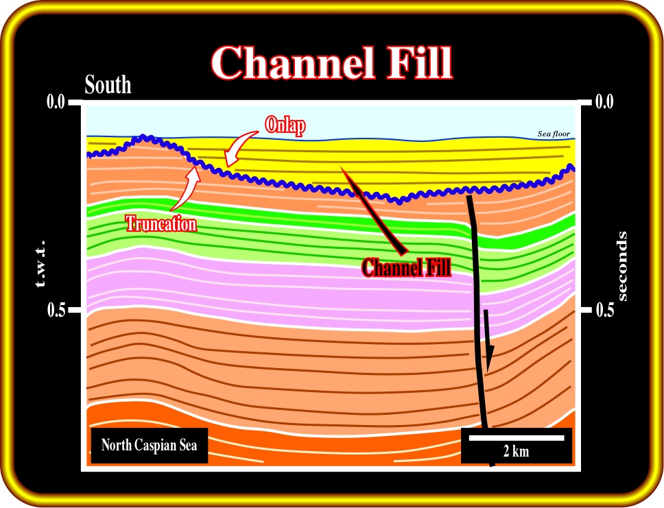
Plate 216 - On this seismic line, a relative sea level fall shifted the coastal onlaps basinward and downward developing a subaerial erosion in the outcropping shelf, which created an external channel fill morphology. Later, when relative sea level rose, the shelf was flooded and the channel were filled, in onlap, by shaly marine sediments. In such geological conditions, the erosional surface is quite regional and so, the channel fill fossilized an unconformity.
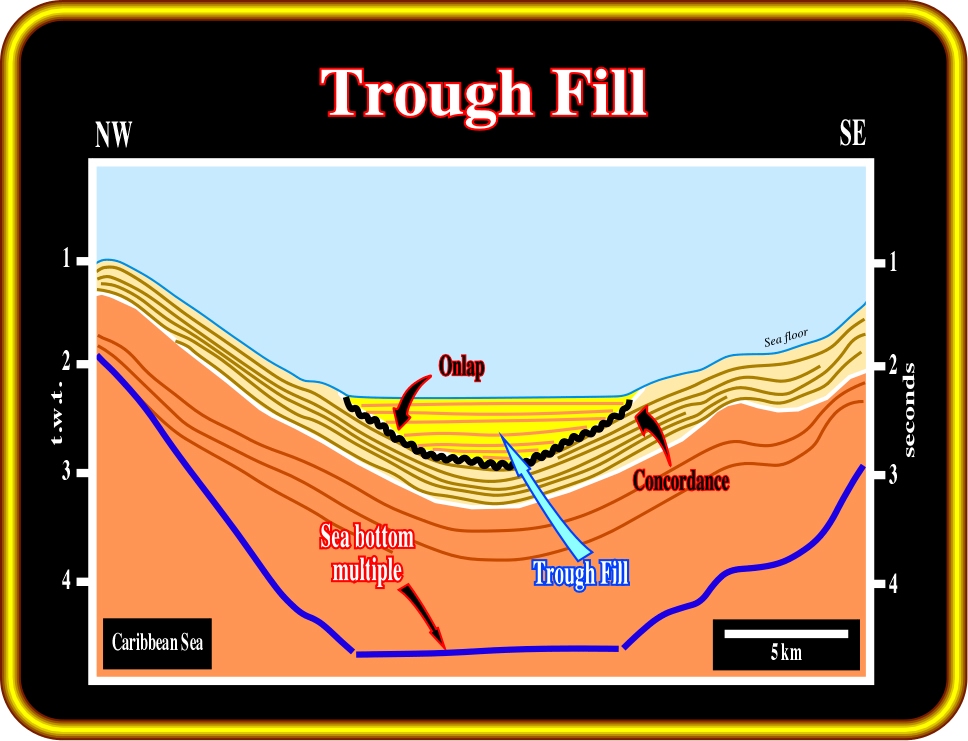
Plate 217 - An external geometry pattern is called trough fill when the depositional anomaly is structural, that is to say, when the depositional surface is not created by local or regional erosion. As illustrated on this seismic line, there is no significant erosion between the yellow and the light brown intervals, in spite of the depositional hiatus between them. In such geological conditions, the trough fill geometry does not necessarily correspond to an unconformity. The internal fill configuration of trough fills can vary considerably.
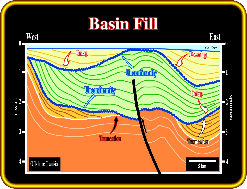
Plate 217 - On this seismic line, when taking into account the external geometrical pattern, one can say that the lower unconformity, at the base of the green interval, corresponds to an external basin fill. Actually, it is quite easy to recognize the underlying reflection terminations of the lower unconformity, which are truncations, and the overlying terminations, which correspond to tilted or deformed onlap. On the other hand, at least two major compressional tectonic regimes are evident. The oldest predates the lower unconformity, while the youngest postdates the unconformity B. Similarly unconformity B, in terms of external fill patterns can also be considered as a basin fill. Truncation (below) and onlap (above) are quite obvious.
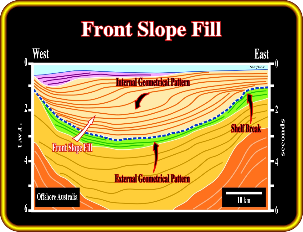
Plate 218 - On this line a front slope fill pattern is illustrated. It is composed by a progradational internal filling configuration. The green seismic interval underlying the front fill depositional surface, corresponds to a front slope fill. The shelf break, limiting the shelf from the continental slope, is easily recognized on the eastern part of the line. There is no significant erosion associated with this front slope fill.
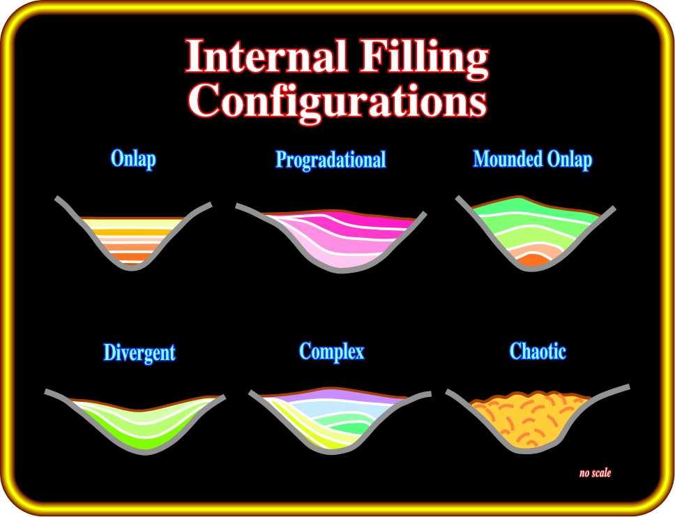
Plate 219 - Taking into account the internal (infilling) geometrical patterns, the fill units can be classified, as illustrated above, into: (i) onlap, (ii) progradational, (iii) mounded onlap, (iv) divergent, (v) complex and (vi) chaotic.
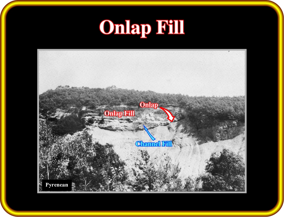
Plate 220 - The internal filling configuration is here clearly onlap. The external channel fill geometry seems to be created by the erosion by gravity currents (turbidite currents). The aggradational geometry filling underlines the stacking of turbidite deposits. In deep-water environments, onlap reflection terminations do not necessary correspond, as it is the case in shallow water deposits, to relative sea level rises. Turbidite depositional systems are most often deposited during relative sea level falls, that is to say, during lowstand geological conditions.
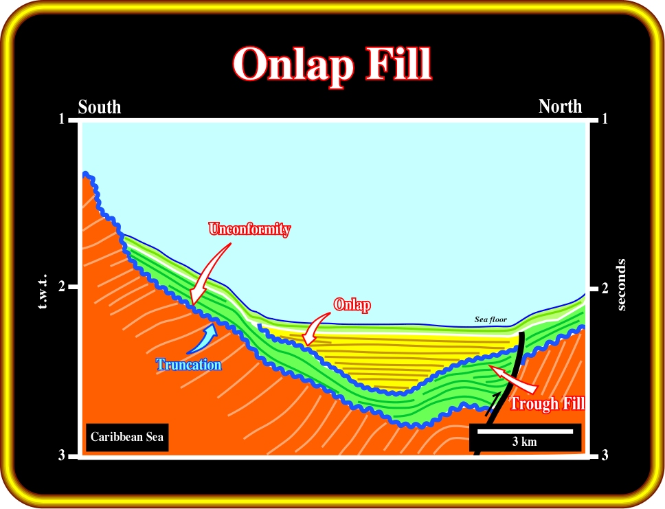
Plate 221- This line illustrates the difference between an unconformity (erosional surface or the basinward correlatable conformity) and a trough fill. Unconformities, as illustrated, are characterized by underlying truncation reflection terminations. In a trough fill there are no underlying reflection terminations. In fact there is concordance. On this line, the structurally induced trough fill was fossilized by deep-water sediments with an internal onlap fill geometry (at least in the N-S direction).
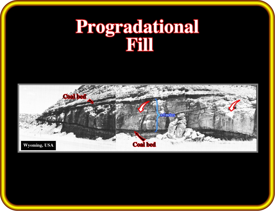
Plate 222 - Progradational reflection configuration, as illustrated on this photograph, can be interpreted as strata that was deposited due to lateral outbuilding or progradation. As we will see later, sigmoid, oblique, complex, shingled and hummocky progradational patterns form through progressive lateral development of gently sloping depositional surfaces, called clinoforms. Differences in prograding clinoforms result in large part from variations in the rate of deposition and water depth.
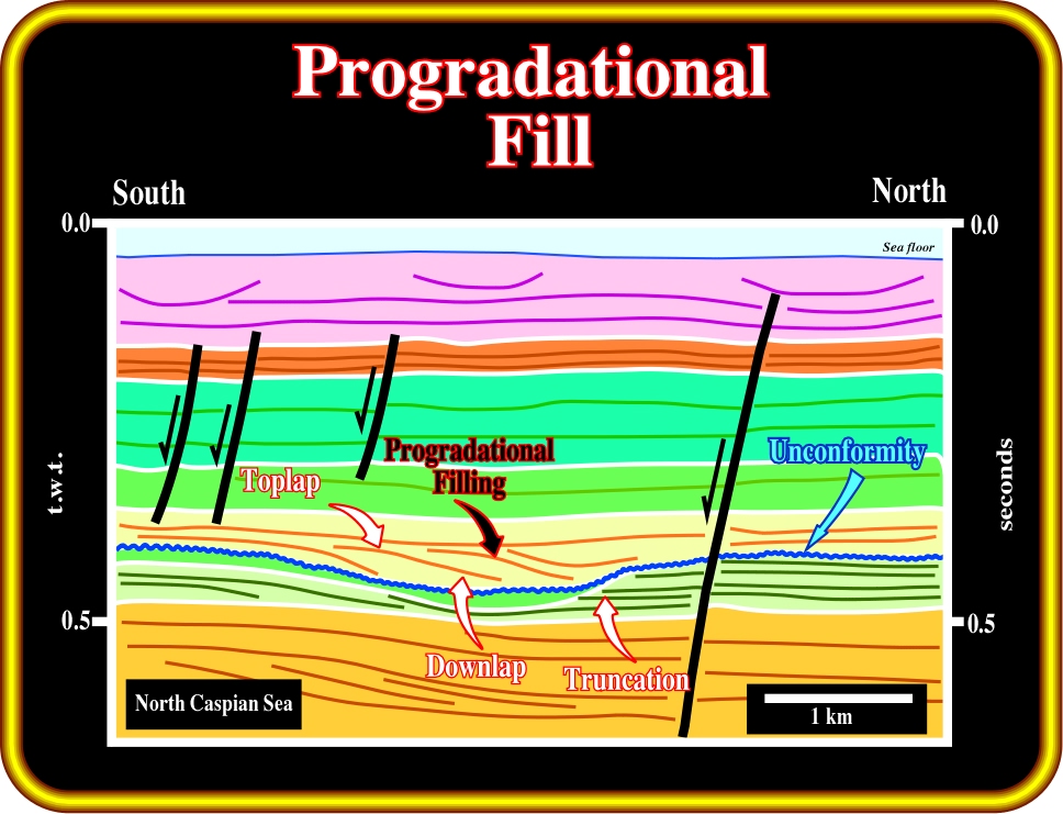
Plate 223 - On this line, an incised valley, created during a relative sea level fall, was later filled by progradational sediments as indicated by the downlap reflection terminations. The downlaps strongly suggest a terrigeneous influx coming from south. Quite often the incised valley, particularly those located near the shelf break, are filled by transgressive sediments, which at a small scale can show a forestepping geometry. The source of clastics sediments is the continent.
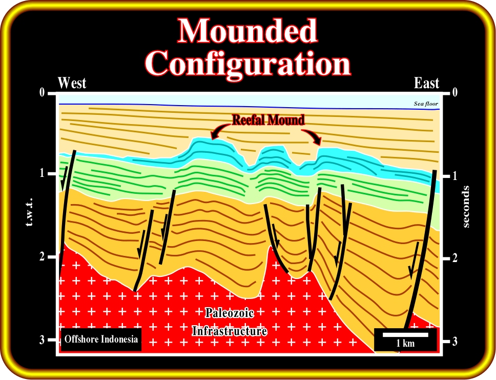
Plate 224 - Mounded reflection configurations are interpreted as strata-forming elevations or prominence's, rising above the general level of the surrounding strata. Most mounds are topographic buildups resulting from either clastic, volcanic depositional processes, or organic growth. On this line from offshore Indonesia, the mounded configuration is obviously associated with reefal buildups.
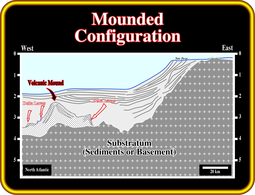
Plate 225- Volcanic mounds are quite frequent, particular in the North Atlantic from where this seismic line comes from. In this particular example, the volcanic mound corresponds to a seamount, with which lava deltas and sub-aerial lava flows (seaward dipping reflections) are often associated. It is important to point out that volcanic material cannot flow under water as it is quickly frozen. The development of lava deltas is due to such behavior.
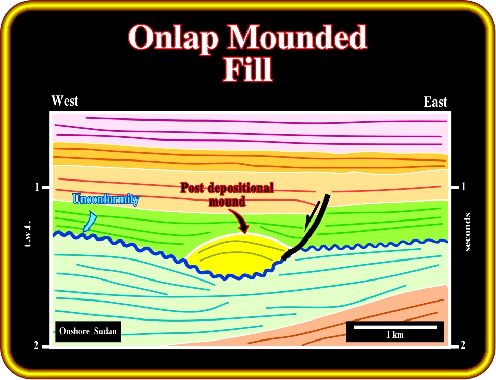
Plate 226- Mounded geometries, and particularly onlap mounded reflection configurations can be postdepositional. Actually, as illustrated on this seismic line, which comes from onshore Sudan (Piber Post Basin), the onlap mound configuration was created due to differential compaction of the sediments. The sandy facies filling the channel are less compacted than surrounding shale sediments. Geologists often use compaction to predict if a channel is filled by sandstones (onlap mound) or clays (absence of onlap mound).
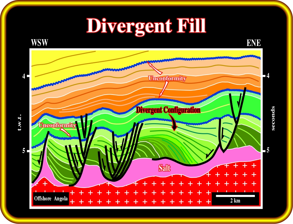
Plate 227 - Divergent fill or divergent reflection configuration is characterized by a wedge-shaped unit in which most of the lateral thickening is accomplished by thickening of individual reflection cycles within the unit, rather than by onlap, toplap or erosion at the base or at the top of the stratigraphic cycle. Divergent configurations suggest lateral variations in the rate of deposition, or progressive tilting of the depositional surface as illustrated on this line from offshore Angola.
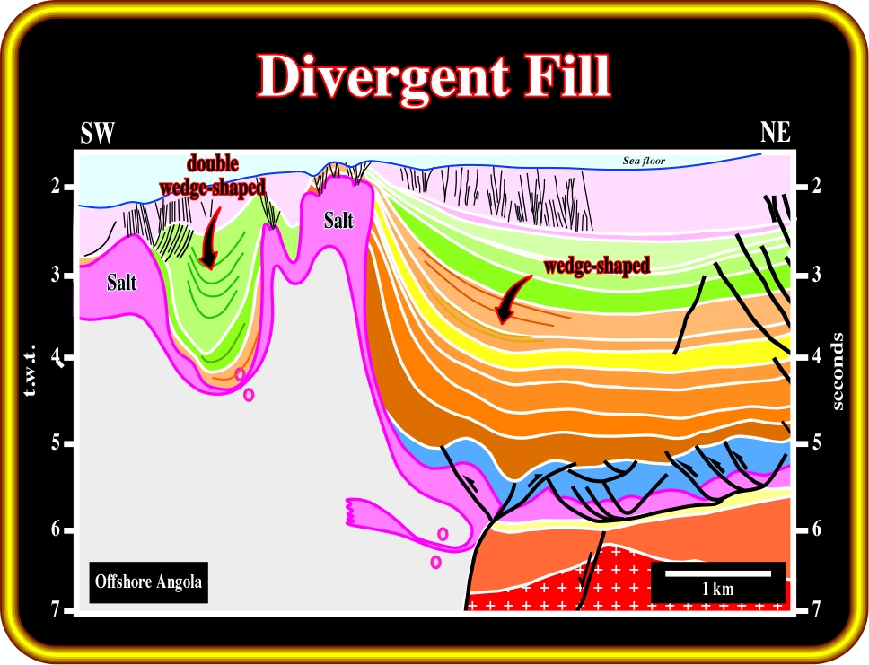
Plate 228 - On this line from deep-water Angola, divergent wedge-shaped configurations are mainly associated with compensatory subsidence induced by salt flowage. In association with allochthonous salt layers, salt expulsion basins (minibasins) are almost always filled by double wedge-shaped convergent sediments. Such a convergent configuration suggests an increasing of compensatory subsidence toward the center of the basin.
to continue press![]()
![]()