LPW).jpg)
(iii) Lowstand prograding wedge (LPW)
As eustatic sea level passes the lowstand position and begins to rise slowly, this effect, combined with continued basin subsidence, begins to move the relative position of the sea upward toward the old shelf-slope break. Rivers deposit shelf sediments beyond the old shelf break and bay, delta and shoreface sands begin to accumulate on the upper topographic slope as relative sea level rises. These units prograde laterally into the basin, resulting in deposits in bathyal to abyssal water depths composed predominantly of shales with a few thin turbidite sands.
If the prograding complex receives a large volume of sand supply, this system may become overloaded and any minor short-term lowstand results in a basin floor turbidite sand at the shingled toe of the prograding complex.
A thick series of shallow marine deltaic and shoreface sands may stack vertically in the updip portion of the prograding complex. Subsequently, differential compaction may result in a closed compaction high over these sands. Because the shelfward lateral seal is poor, these shallow marine sediments generally require structural closure to trap hydrocarbons.
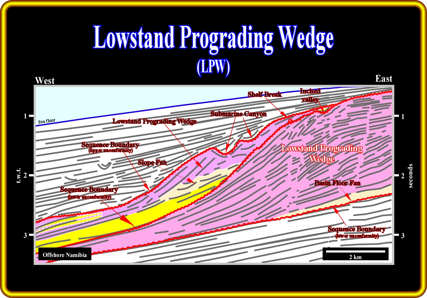
In Namibia deep offshore, as illustrated on this geological tentative interpretation, lowstand prograding wedges (PLW) are paramount. Two incomplete sequence-cycles are individualized by sequence boundaries easily recognized by onlap and toplap (truncation) seismic surfaces and associated incised valleys. Lowstand prograding wedges are not necessary formed by deep-water sediments. In fact, shallow water depositional systems, such as deltas, for instance, are often present landward of shelf breaks. Seaward progradation gives the overall forestepping geometry of lowstand prograding wedge (LPW). In the upper sequence-cycle, the lowstand prograding wedge (LPW) fossilizes, progressively, the slope fan (SF) and the basin floor fan (BFF). On the other hand, shingled turbidites were deposited at the toe of the distal progradation. In the lower sequence-cycle, which is also incomplete, the lowstand prograding wedge fossilizes the lower sequence-cycle boundary and the distal part of a slope fan.
Prograding complex sediments typically infill any associated submarine canyons cut into the old shelf margin during the late stages of the prograding complex time. These sediments also infill in the shelf, the river valleys.
At the end of prograding complex time, eustatic sea level begins to rise rapidly and a major flooding event occurs, starting the transgressive systems tract. Sand at the top of the prograding complex and on the adjacent shelf is reworked by this marine invasion, which is typically followed by deposition of marine transgressive shales, which provide a topseal for all lowstand system tract units.
In electrical logs, lowstand prograding wedges are characterized a positive log-sequence, that is to say, by a coarsening and thickening upward log interval, as illustrated below.
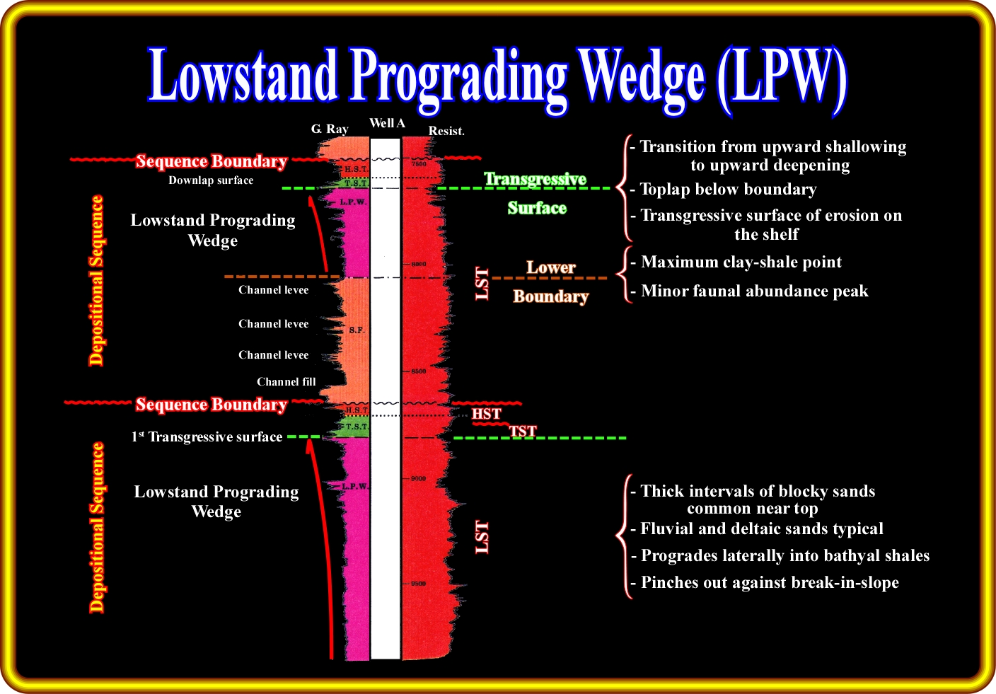
The log patterns associated with a lowstand prograding wedge (LPW,) are depicted here. Roughly speaking, one can say, that they emphasize a coarsening and thickening stratigraphic interval. In other words, in sand-shale facies, the sand layers are thicker and coarsening toward the top of the lowstand prograding wedge. In terms of relative sea level, one can say that the sand layers are thicker and coarser as the sea level rises in acceleration. The top of the lowstand wedge is defined by a flooding surface produced when the rate of sea level rise reaches its maximum.
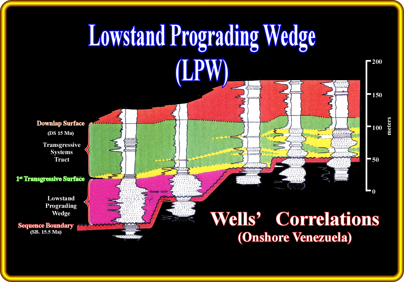
This figure illustrates the sequential stratigraphic correlation between five wells located in an onshore basin of Venezuela. The 15.5 Ma sequence-cycle boundary is easily recognized in the majority of the wells. On seismic lines, it corresponds to a quite evident onlap seismic surface and in the electrical logs, as depicted above, to the limit between a coarsening and thickening interval and a thinning and fining upward interval. Two wells penetrated the lowstand prograding wedge (LPW) seaward of the 15.5 Ma shelf break. The lowstand prograding wedge is overlain by a transgressive systems tract (TST), which landward of the 15.5 Ma shelf break, overlies directly the 15.5 Ma sequence-cycle boundary. In other words, landward of the 15.5 Ma shelf break, there is no lowstand prograding wedge. In hydrocarbon exploration terms, the sandstone horizons of the lowstand prograding edge are hydrocarbon bearing as well as the landward thickening transgressive sandstones. These correlations strongly suggest the oil trap is fundamentally non-structural, probably stratigraphic. Such a conjecture is not refuted ; the seismic lines crossing the field corroborate it.
The exploration applications of lowstand prograding wedges were summarized by Vail (1989) as follows :
1) RESERVOIR
- Variable. Stacked fluvial, deltaic and shoreface;
- Variable continuity2) MIGRATION
- Probably depends on fault conduits from deeper source ;
- Possible downward migration from transgressive systems tract (TST).3) SOURCE
- Deeper beds or transgressive systems tract (TST) source at top.
4) TRAP
- Typically structural.
- Possible compaction closure.5) SEAL
- Good transgressive systems tract (TST) seal.
- Lateral seal may be poor.
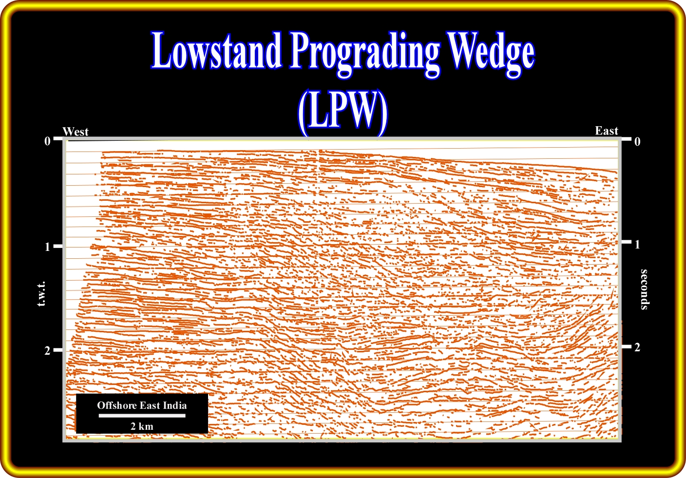
On this sketch of a seismic line from offshore East India, a major unconformity and a lowstand prograding wedge (LPW) is easily recognized by its forestepping geometry overlying a thick slope fan (SF). The "gull wing" geometry, with its opposite downlaps and the seaward displacement of the successive lowstand shelf breaks of the lowstand prograding wedge (LPW) are evident enough for a tentative solution to be proposed.
A. 3) Turbidite deposits associated with LST
As depicted below, the turbidite deposits associated with the lowstand systems tract (LST) can occur in all of the three member:
A.3.1) Lowstand Prograding Wedge (LPW) :
- Shingled Turbidites.
A.3.2) Slope Fan (SF) :
- Canyon Fill or Slump Blocks ;
- Overbank Deposits ;
- Distal Overbank Mudstones ;
- Channel Sands ;
- Basin Floor Thin Bedded Turbidites.A.3.3) Basin Floor Fans (BFF) :
- Sheet Lobe Facies ;
- Unamalgamated Turbidites ;
- Amalgamated Turbidites ;
- Channelized Facies ;
- Contourites.
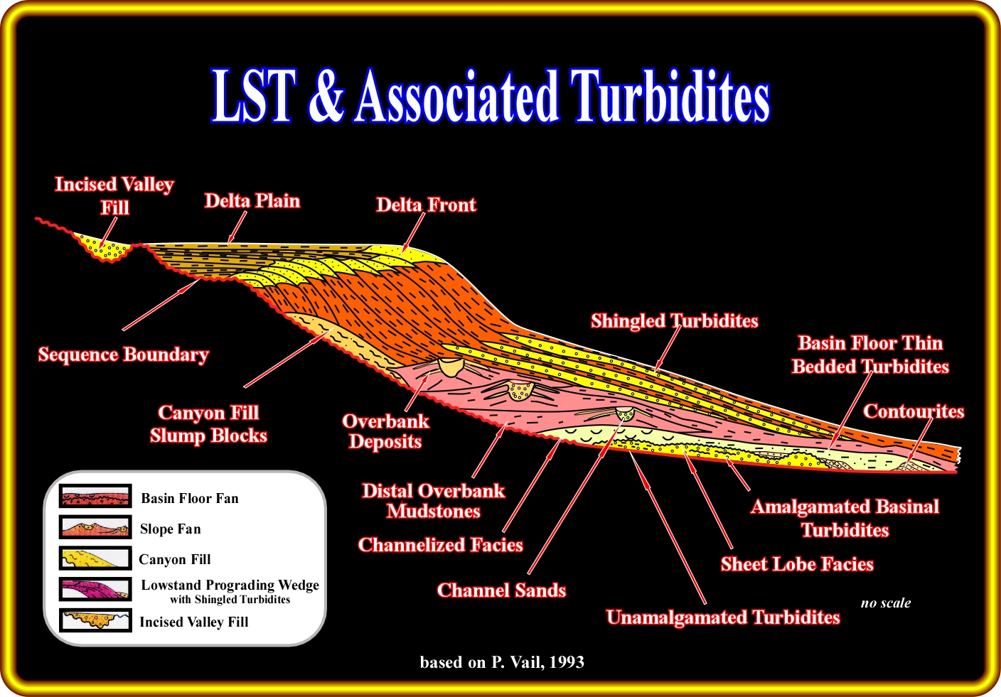
Several types of turbiditic deposits are associated with lowstand systems tracts. In the lower member, i.e., in a basin floor systems tract, the following turbidite depositional systems can be found : (i) Amalgamated basinal turbidites ; (ii) Unamalgamated turbidites ; (iii) Sheet lobe facies ; (iv) Channelized facies ; (v) Basin floor thin bedded turbidites and (vi) Contourites. In the slope fan systems tract, one can find : (i) Overbank deposits ; (ii) Distal overbank mudstones ; (iii) Channel sands with associated and (iv) Canyon fills and slump blocks. In the lowstand prograding wedge systems tract, shingled turbidites are often found at the toe of the progradations.
Similarly, the logs patterns associated with the turbidite deposits of a lowstand systems tract are quite characteristics and can be depicted as below.
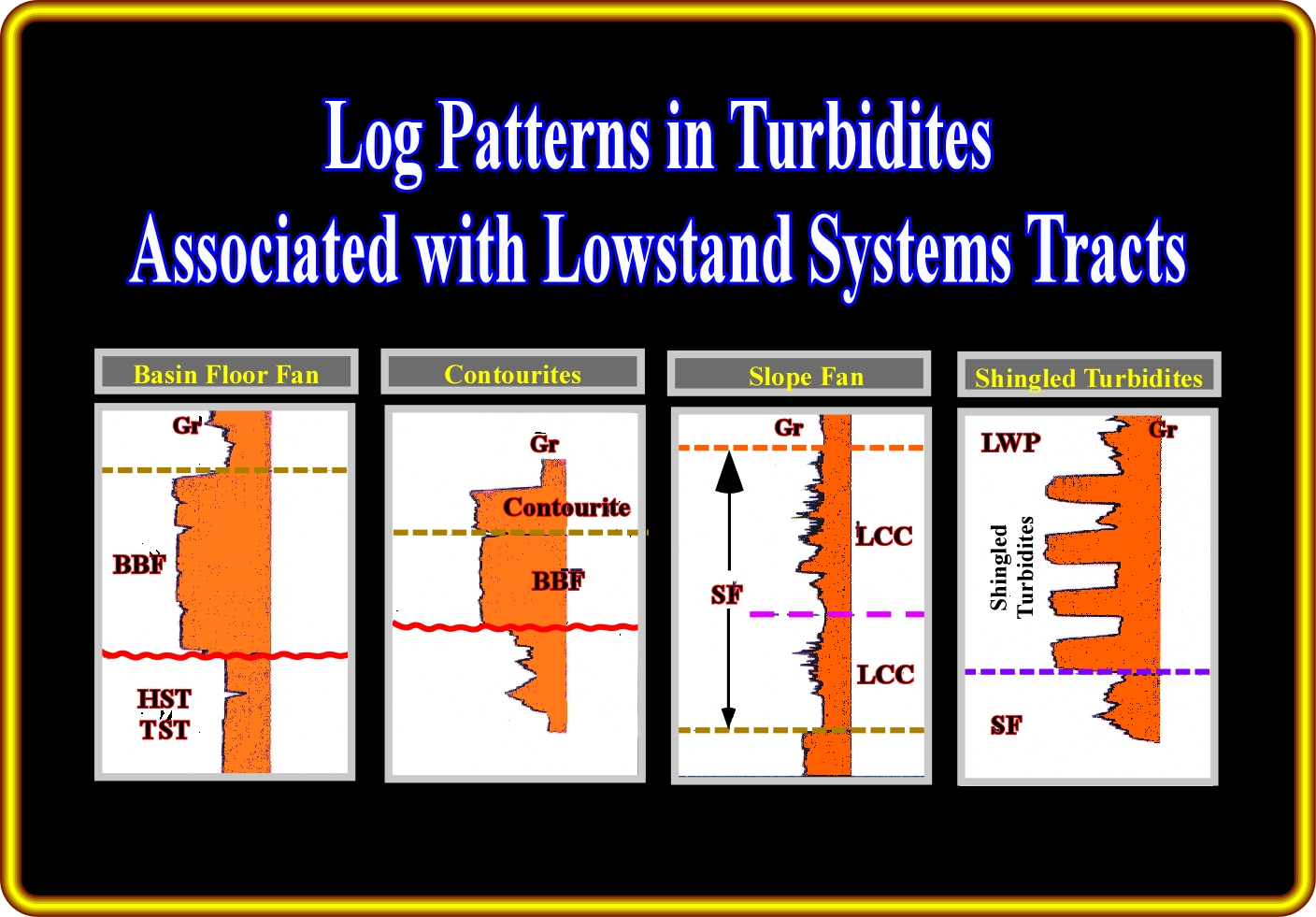
On this sketch the more likely log patterns associated with the lowstand turbidite depositional systems are summarized. The log pattern of the basin floor fan has a general cylindrical morphology with quite abrupt upper and lower limits. The log pattern of contourites is similar to that of the basin floor fan, but the internal parallel configuration is generally dipping seaward or concordant with the sense of the bottom sea floor current. The log pattern of a slope fan, as said previously, is characterized by a stacking of increasing and decreasing thickness patterns with interbedded channelized patterns. The log pattern of the shingled turbidite is characterized by a stacking of cylindrical boxy shaped sandstones separated by significant shaly intervals.
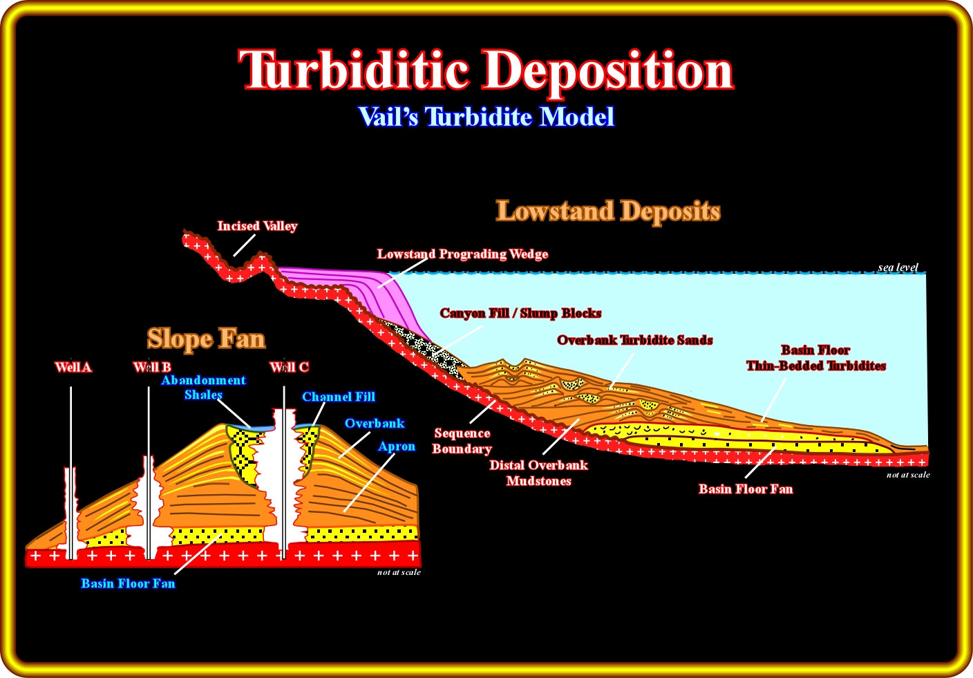
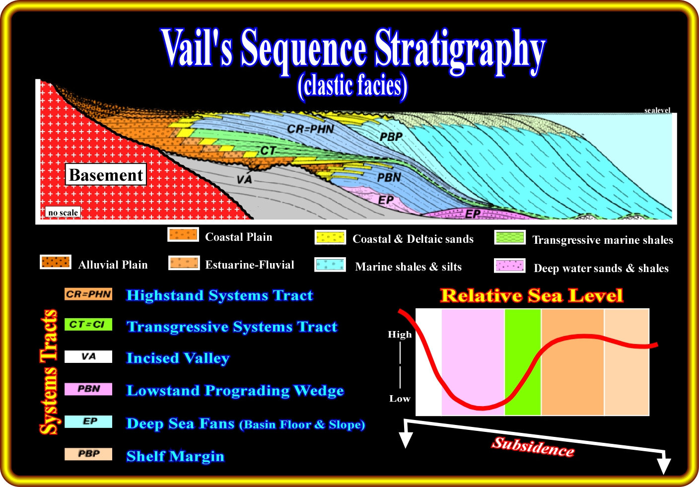
In the Vail’s model, basin floor fans are deposited at the bottom of a depositional sequence (or seismic sequence), when the relative sea level is at the lowest point of the eustatic curve. Their geometry is mainly tabular (blanket like sheet) and their facies is sandy. Slope fans are mainly composed by channel-leveed complexes. They are deposited during lowstand geological conditions, when the relative sea level start to rise (in acceleration) from its lower point. Their geometry is mounded (gull wing geometry of Vail). The lithology of the slope fans is more complex that that of the basin floor fans. At the bottom, a shaly apron is usually recognized, underlying over-bank deposits and channel fills. The reservoirs facies are principally located in the channel fills. The reservoirs facies associated with the over-bank deposits (Vail’s gull-wings) are too thin. They can only be considered as alternate or auxiliary reservoirs.
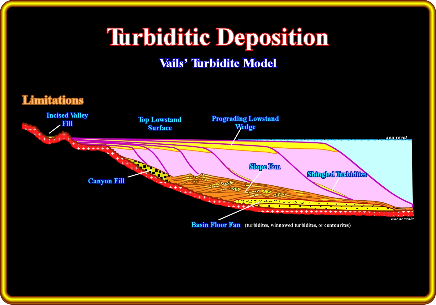
The main limitations of this geological model were summarized by E. Mutti (1992) as follows: (i) The model is essentially based on the seismic expression of deep-water depositional systems. It suffers several limitations because of lack of supporting sedimentological data from extensive core analysis and or field studies ; (ii) The model is mainly derived from continental margins and cratonic basins affected by bottom currents. Relations in space and time between turbidite systems, mixed, and contourite systems are not discussed ; (iii) The model entirely relies on relative sea-level variation driven by 3rd-order eustatic cycles ; although it provides a very valuable predictable pattern of gross facies relations within unconformity-bounded units ; the model cannot be used for predictive purposes in terms of actual types of facies and geometry of turbidite sandstone bodies. Deep-water siliciclastic systems are considered as restricted to periods of sea-level lowstand ; (iv) High-frequency cyclicity of deep-water systems is virtually ignored ; (v) Both basin-floor and slope fans are sourced by sand carried by rivers directly onto the slope ; (vi) The model cannot really be used to describe and interpret turbidite systems of thrust-fold belts, where, in most cases, rates of tectonic deformation clearly exceeded rates of eustatic variation and activity of bottom-current was negligible.
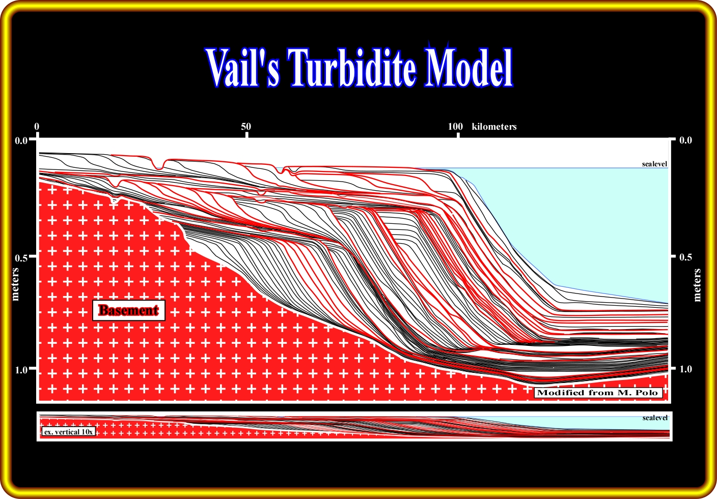
The Vail’s turbidite model is illustrated here above using the Marco Polo software. This model, which is mainly based on eustasy, was proposed during the 1960s and 1970s when Exxon’s geologists develop the concepts of sequence seismic stratigraphy. However, the geological concept of eustasy was invoked since long time to explain the cyclicity of the geological deposits (Maillet, B. de, 1748; Lavoisier, M., 1789; Suess, E., 1888; Chamberley, T.C., 1910; Lemoine, 1911; Grabau, A., 1936; Burrolet, P., 1954, etc.). Turbidite deposits (slope fans and basin slope fans) take place during lowstand geological situations, when the basin has not platform. In fact, a significant relative sea level fall can completely emerge (exhumed) the platform (shelf) with the sea level below the ancient shelf break. In such a geological conditions, sediments are transferred to the slope and abyssal plain, by gravity currents, where they will be deposited forming slope and basin floor fans.
Three basic driving concepts are at the origin of seismic sequential stratigraphy : (i) Time lines can be determined from the physical stratigraphy ; this allows facies interpretation within the time-stratigraphic framework determined earlier from bedding-surface correlation ; (ii) Seismic reflections do not follow massive time transgressive formational boundaries, where strong impedances occur, but instead they follow the detailed bedding patterns or the real physical surfaces on the rocks ; they cross time-transgressive facies and rock formation boundaries, which are not continuous physical surfaces ; (iii) Eustasy is the principal cause of the onlap cycles. The building block of seismic stratigraphy is the seismic sequence-cycle, i.e. a depositional sequence-cycle (a relatively conformable succession of genetically related strata bounded at its top and base by unconformities) identified on a seismic line. Often, five systems tracts compose a seismic sequence. On the other hand, different depositional systems (lithology + fauna) can be identified within a systems tract.
to continue press
![]()
Send E-mail to carloscramez@gmail.com with critics, corrections or commentaries on these Turbidite Deposits notes.
Copyright © 2001CCramez
Last modification : November, 2013