
B) Mutti's Model
Admittedly, the more used classification of turbidite systems are based either on the volume and texture of the gravity flow (sand-rich / mud-rich systems or type I, II and III of Mutti, 1985) or linked to the physiography of the margin and predominant sediment granulometry of coastal systems (Reading & Richard, 1994). However, as in petroleum exploration, the fundamental parameter in turbidite systems is the occurrence and location of potential sandstone reservoirs. Subsequently, here, we are going to use the classification based on this parameter. So, assuming that the turbidity currents have a high degree of freedom, that is to say, in absence of effective obstacles along the slope, one can divide turbidite deposits into :
A) Large Turbidite Systems ;
B) Middle Turbidite Systems ;
C) Small Turbidite Systems.
Such a classification takes into account the "efficiency" concepts of Mutti (1979), and it corresponds to his classification proposed in 1985, and in which, he divided turbidite systems into 3 "types":
- Type I, mainly composed of tabular lobes (roughly the basin floor fans of Vail) ;
- Type II, mainly composed of transition channel-lobes ;
- Type III, composed mainly of channel-levee complexes (roughly the slope fans of Vail).
Nevertheless, this classification does not subdivide systems (or turbidite complexes within an eustatic cycle) in a lateral-vertical succession of stage of type I, II, III. In fact, at the scale of facies sequence (15-30m), very often, middle turbidite systems show, in the lower part, channel-lobe transition facies (F2-F5, characteristic of system type II of Mutti) and bypass facies (F6) associated to proximal lobes (F7), which characterize the type I of Mutti, in the middle and upper part (see later).
Considering the 1985 Mutti’s classification we will get stages of type II followed by type I, which is in total contradiction with Mutti’s model (1985). In these notes, we will adopt an operational classification in order to evaluate, on the basis of morphologic criteria (seismic data) and the facies sequence (the cores and field), the presence and extension of potential reservoirs. However, the terms large, middle and small do not make any reference to the size of the systems themselves but to the relative extension of the sandy facies, i.e. the potential reservoirs.
On the other hand, and in contrast with Mutti (1985), we consider a turbidite system at the scale of the stratigraphic cycle (sequence-cycle, or continental encroachment subcycle (see Duval et al., 1993)), and not at the scale of the depositional system sensu strito composed by different depositional elements such as bypass zone, with scours and residual lags, depositional zone with lobes, etc., which do not require us to introduce different hybrid depositional unities, i.e. the stages of growth proposed by Mutti.
The geological features characterizing the Large (LTS), Middle (MTS) and Small Turbidite Systems (STS), can be summarized as follows.
Large Turbidite Systems (LTS) :
- Slope failures ;
- Large scale submarine erosions, i.e., erosion all along the continental slope ;
- By-pass zone at the toe of the continental slope ;
- Deposition of lobes on the abyssal plain.Middle Turbidite Systems (MTS) :
- Coastal depositional systems near the shelf break, i.e. depositional coastal break and shelf break more or less coincident (basin without shelf) ;
- Erosion along the upper continental slope ;
- Deposition takes place directly at the toe of the continental slop ;
- There is an absence or a very small by-pass zone.Small Turbidite Systems (STS) :
- They take place during the progradation of the shelf break (continental slope has forestepping geometry) ;
- Rectilinear or sinuous channels along the continental slope ;
- Sandstone terminal lobes at the end of the rectilinear channels ;
- Siltstones terminal lobes at the end of the sinuous channels.
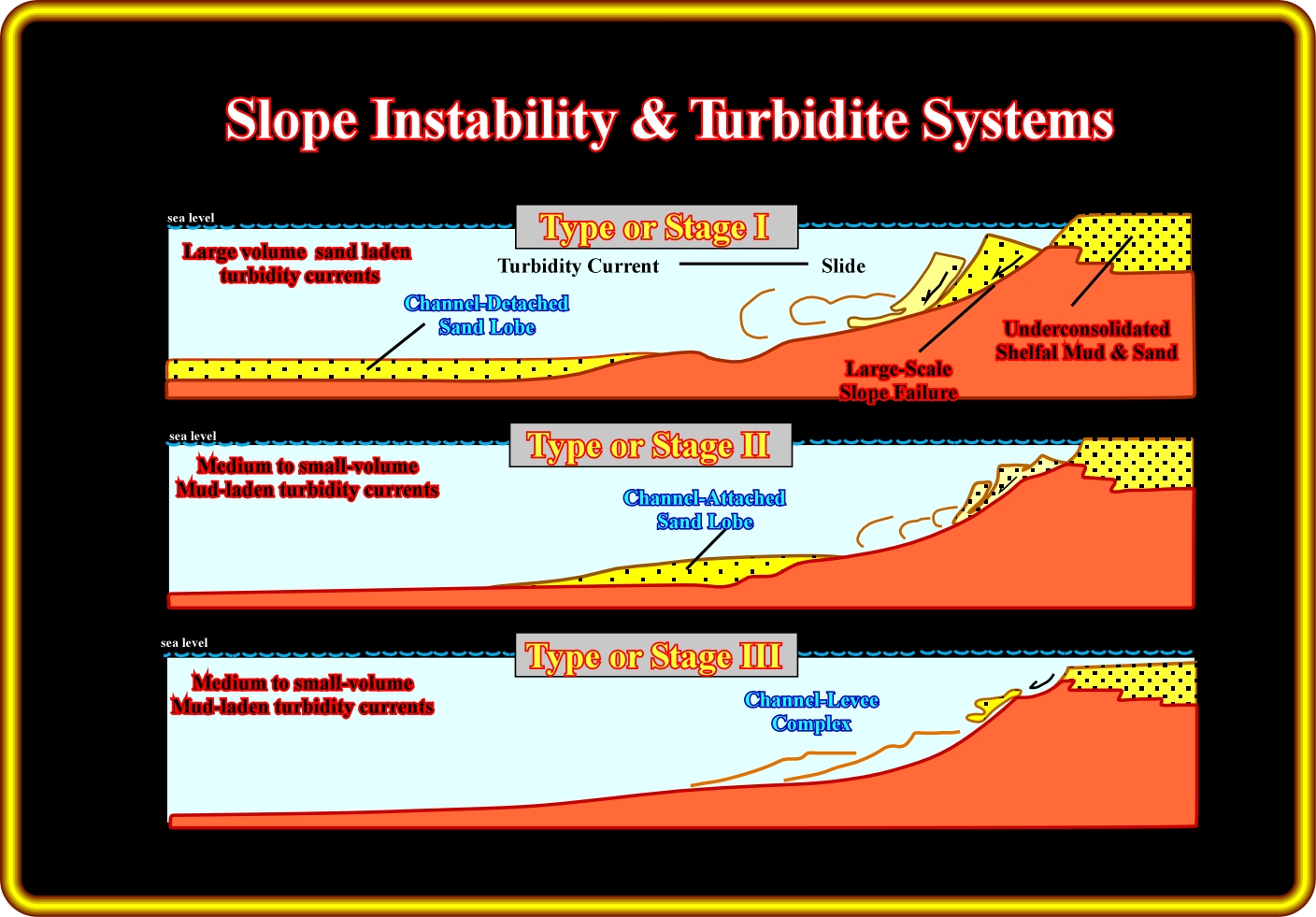
There is a relation between the types of turbidite systems and the volume o gravity flows. In Type I, individuals beds and groups of beds that occur in lobe commonly reach volumes of the order of 1 to 10 km3. The later volume is comparable to the sediment volume of modern channel-mouth bar in a large delta complex. In Type III, thin and laterally impersistent beds of sandstone, and the abundant associated thin to very thin-bedded silty mudstone, suggest flows of rather small with relatively high proportions of mud. Geometry of sandstone beds and bodies in Type II systems indicates flows of intermediate volume, generally with relatively high proportions of sand.
B.1) Large Turbidite Systems (LTS)
Large turbidite systems (LTS) are characterized by a large zone of non-deposition, or/and by residual deposits between the continental slope and the most proximal part of the abyssal plain. The other major geological features are :
- The main depositional zone is located in the abyssal plain ;
- The bulk of sandstones occur in non-channelized and elongated lobes in the outer area of the system ;
- The potential sand-prone reservoirs have a tabular geometry with tens of kilometres of extension ;
- The individual strata thickness range between 0.5 and 2 meters ;
- The thickness of each lobe, commonly ranges between 3-15 m thick ;
- The total thickness of each system can reach 50-100 m with a sand/shale ratio (N/G around) of 50% ;
- Each lobe is thick-bedded and grades seaward into thinner bedded and finer grained deposits ;
- They create huge morphologic traps with large four way dip closures.
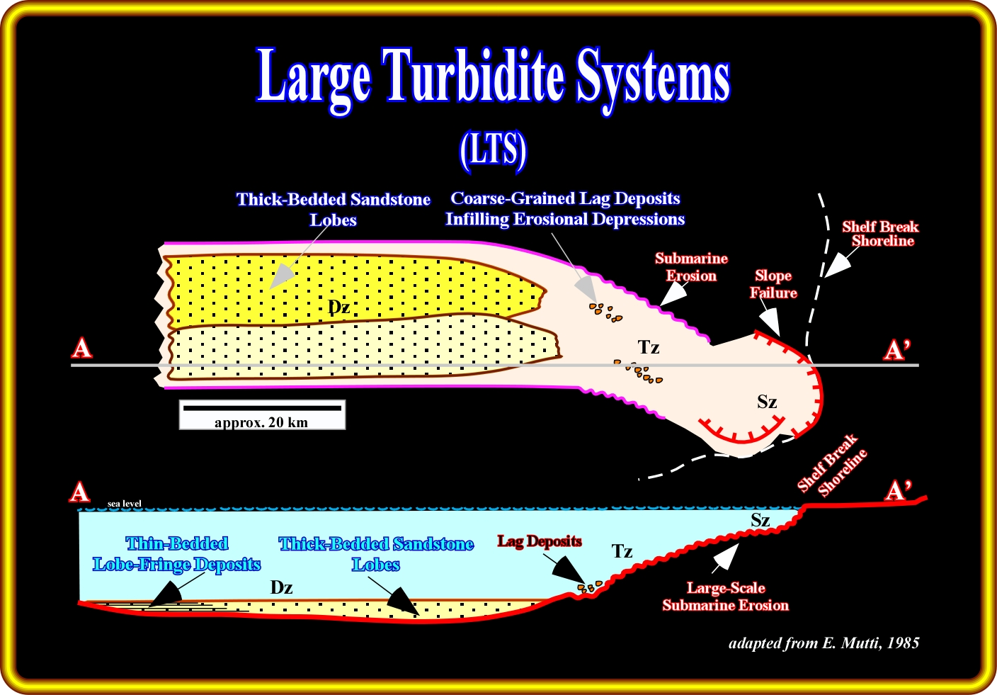
In large turbidite systems (LTS), the bulk of the sandstone occurs in non-channelized and elongated bodies (lobes) in the outer region of the system. These potential reservoirs are characterized by lateral continuity and a tabular geometry over distances up to several tens of kilometres parallel to the current direction. The thickness of each lobe commonly range between 3-15 m thick; it is characteristically thick-bedded and grades in a down-current direction into thinner bedded and finer grained deposits.
As illustrated above, in a LTS, there is an important zone of bypass between the shelf break and the proximal area of the abyssal plain. Locally, in the bypass zone, chaotic coarse-grained lag deposits fill deeper erosional features. In the uppermost part of the system, the shelf break, which corresponds to the shoreline (lowstand), may be located at a slope failure induced by slump. The majority of the sediments are deposited in the abyssal plain forming non-channelized elongate lobes, which are mainly composed of sandstones, i.e. potential HC reservoirs.
During the retrogradational (backstepping) infilling phase, the lobes are progressively deposited landward in the direction of the bypass zone. They can be deposited directly in a canyon, if a canyon was developed. The final infilling phase is often culminated by small turbidite systems (STS), in which channel-levees complexes are predominant. Straight channels (often sandprone) or sinuous channels (often shaleprone) are very often recognized.
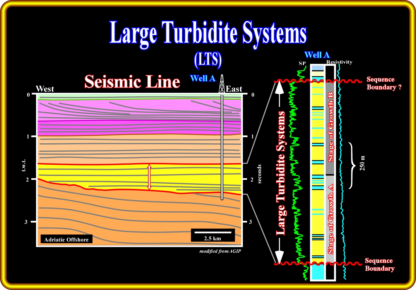
This geological tentative interpretation of detail from seismic line of the offshore Adriatic illustrates a LTS (large turbidite system) overlying the Messianian unconformity (SB. 5.5 Ma). From bottom to top, six major seismic intervals are easily recognized. The lower one is limited at the top by a tectonically enhanced unconformity, which is fossilized by onlapping of turbiditic sediments composing the yellow interval, which has a parallel internal configuration. This interval corresponds to a LTS, which was deposited at the toe of the slope of the SB. 5.5 Ma. Such a conjecture was corroborated by the results of well A. The electrical logs, and particularly the SP (spontaneous potential), have the typical signature of stacking of turbidite lobes. The total thickness of the systems is more than 1000 meters. However, without knowing the age of the upper unconformity of this interval, it is difficult to hypothesize if it corresponds to a unique system or to the stacking of two or three systems. As illustrated in this geological tentative interpretation we assume a unique LTS with two phases of infilling. The lower one is predominantly aggradational / forestepping and the upper one is mainly aggradational / backstepping.
On this subject, it is interesting to notice that in the Congo (northern Angola offshore included), as well as, in the Amazon offshore, seaward of the deltaic environments, the final STS infilling phase is extremely important not only in terms of thickness but in terms of extension as well. Nevertheless, one should not to forget that the lobes of the LTS are deposited hundred of kilometres seaward directly over the oceanic crust. This seems to be particularly true in northern Angola offshore (Congo basin), where the bathymetric map of the area suggests a large deep sea fan seaward of the present Congo Canyon.
On dip seismic lines (more or less perpendicular to the slope), seaward of the bypass zone, the geometry of LTS is the one recognized on the Adriatic line (last plate). It can be schematised, as depicted on top of next, where the seismic reflectors associated with the turbidite lobes can be easily followed in continuity for dozens of kilometres. In favourable cases, it can be recognized that the lobes onlap landward on seismic surfaces correlative with an unconformity. The thickness of each lobe is difficult to determine. However, the total stacking thickness can reach thousands of meters, relying upon the efficiency of the systems. On strike seismic lines, the geometry depends on how seaward the line is located. To simplify, one can consider the three cases :
1) Lines located in the Upper to Middle Slope
On such lines, very often, it is possible to identify a canyon or submarine valleys (SUV) created or/and used by the currents to reach the abyssal plain. In many cases the geometry is similar to giant “gull wings” and is induced by deposition of huge overbank shaly deposits. The central area corresponds to the bypass zone, where there is no deposition, since the turbidity-currents are too competent. Later on, during the retrogradational infilling phase, the bypass area is filled by turbidite deposits, generally, belonging to middle or small turbidite systems.
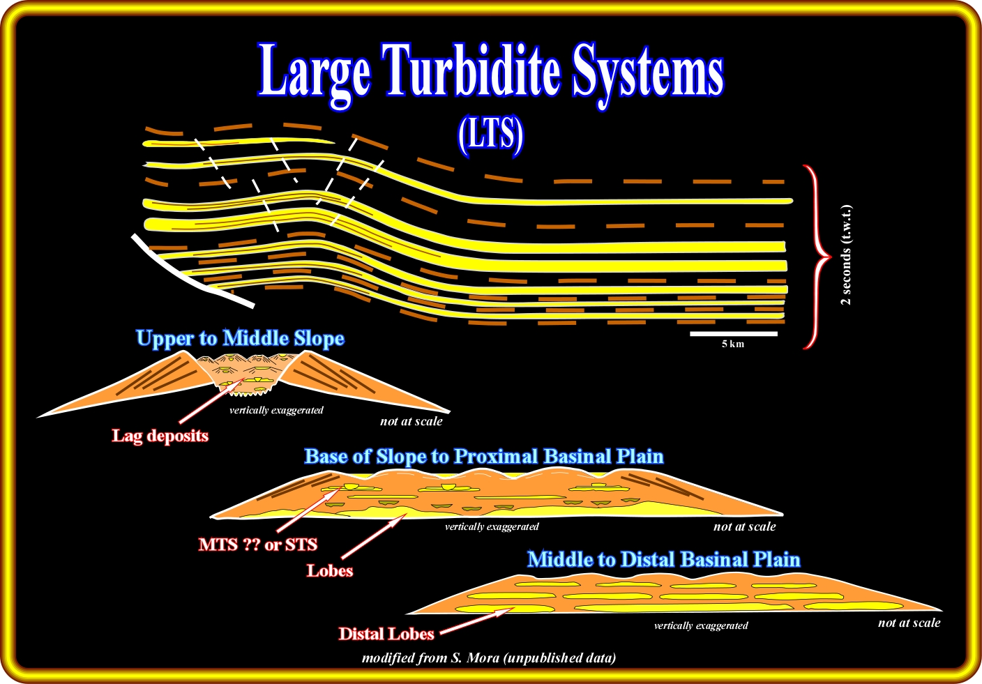
In a LTS, from the abyssal plain to the upper-middle slope, three signatures are often recognized. In the deepest area, between the middle to distal abyssal plain, we find the distal lobes. They are well individualized with relatively thick shale intervals between them. Landward, between the bottom of slope and proximal basinal plain, the lobes are thicker and generally coalescent. They are overlain by middle or small turbidite systems. Between the upper and middle slope, lag deposits and channel levee complexes can be recognized.
2) Lines located between the base of Slope and Proximal Basin Plain
On such lines, we recognize many times the proximal end of the lobes. Generally, they are quite thick and frequently they are coalescent forming huge potential hydrocarbon reservoirs. Such large and thick reservoirs require well-defined structural traps (four way dip closures). The hydrocarbon parameter “retention” is critical. Overlying the major lobes, small lobes associated with rectilinear channel and channel-levee complexes are often recognized. They can be related with middle (MTS) or small turbidite systems (STS).
3) Lines located between the Middle to Distal Plain
On such lines, the distal proximal end of the lobes is, generally, easily recognized. Obviously, their thickness is smaller than in LTS’s and, generally, they are not coalescent. On contrary, they are well individualized and surrounded seaward by sealing shales. In such a condition, they form good potential reservoirs which can be located not only in structural traps but in morphological and stratigraphic traps as well.
B.2) Medium Turbidite Systems (MTS)
Middle turbidite systems (MTS) are very sandy systems deposited at the bottom of the continental slope. They are deposited between the lower section of the continental slope and the proximal section of the abyssal plain. Their geometry is typically radial. The amount of sand present in the alimentation zone controls their extension.
(i) The more sandy systems (N/G>80) are deposited at the base of the slope :
- Their extension is relatively small (around 10-15 km) ;
- They change laterally into thin-bedded-turbidites (medium-small systems).(ii) The sand systems (N/G between 80-50%) are deposited mainly on the abyssal plain :
- Their extension reaches several tens of kilo meters (medium-large systems) ;
- The thickness of individual strata ranges between 1-5 m and they are often amalgamated.The total thickness of medium turbidite systems (MTS) ranges between 100 and 200 meters. Potential reservoir associated with these systems are best targeted in hydrocarbon exploration, since, very often, the trapping mechanism is mainly morphological or morphological by juxtaposition (ex: Roncador, Marlin, etc.).
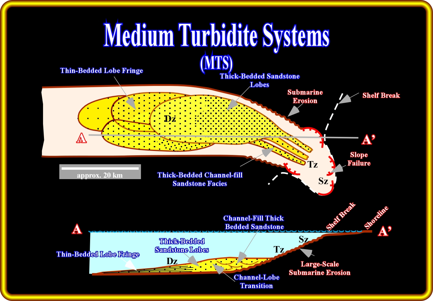
Medium Turbidite Systems include all those depositional settings where sandstone facies are predominantly deposited in the lower reaches of channels and in the regions beyond channel mouths. These systems form extensively channelized bodies that grade down current into sandstone lobes. Very coarse-grained Type II systems are almost entirely composed of channelized deposits. Decrease of grain size tends to favour the development of associated lobes. However, the lobes are consistently less developed, in both volume and area extend, than those of large turbidite systems.
During the backstepping infilling phase, they deposit sandstones in the associated canyon or SUV (submarine valleys, see later). During the de-activation phase, they change to small turbidite systems composed by rectilinear erosional channels with terminal lobes at their mouth (suprafans of Normark). At the end of their history, also, they are covered by small turbidite systems, but by ones less developed than those covering LTS.
Middle turbidite systems (MTS) are found all along of the South Atlantic offshore. The majority of the oil discoveries in Brazil and some of West Africa deep offshore were made in sandstone reservoirs belonging to middle turbidite systems. Nevertheless, the petroleum systems of the two areas is quite different.
I) Generating Petroleum Subsystem
- In Brazil, margin hyper-saline lacustrine source rocks form the generating petroleum subsystem. They are located immediately below the autochthonous evaporites. Their organic matter is type I.
- In West Africa, the main source rocks are either the rift-type lacustrine source rocks (OM type I) or the marine transgressive sediments (OM type II) associated with the major downlap surface of the post-Pangea continental encroachment cycle, i.e. Cenomanian-Turonian sediments.
II) Reservoir / Entrapment Petroleum Subsystem
- In Brazil, as illustrated, the main sandstone reservoirs are in the lobes located at the toe of the progradations.
- In West Africa, the main reservoirs are the sandstones infilling the rectilinear channels. The lobes beyond the channels mouths seem to be very distal in large depths, probably in the ultra-deep areas.
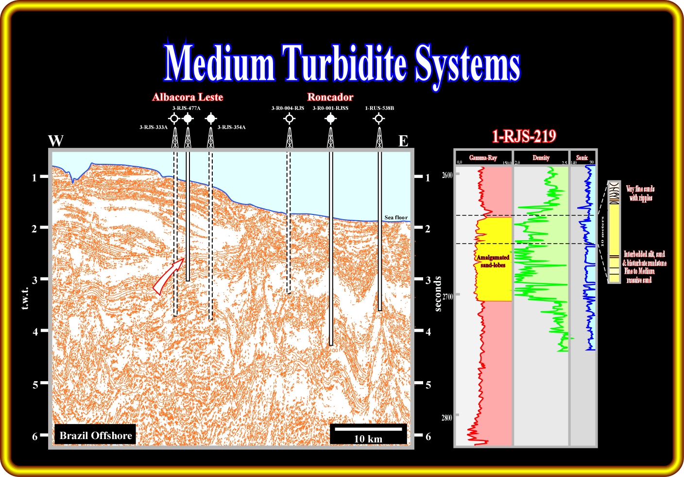
In Brazil offshore, the main sandstone reservoirs are associated with amalgamated sandstone lobes located at the bottom of the continental slope. The reservoirs located in the lower reaches of the turbidite channels are secondary reservoirs. Their contribution for the total reserves is quite small.
The geometry of the sand lobes is generally well recognized. If the line is long enough, as illustrated in the sketch below, it is possible to recognize the proximal and distal onlaping associated with the lobes. In favourable situations, the backstepping depositional geometry it is often recognized. Upward and landward of the more or less stacked lobes, very often, it is possible to recognize channel fills (rectilinear or sinuous).
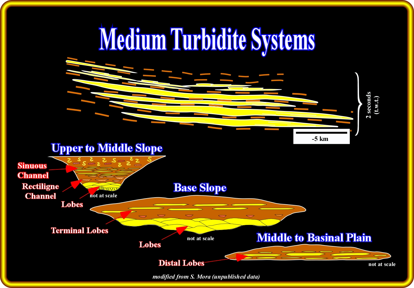
The geometry of middle turbidite systems (MTS) can be deducted using dip and at least three strike lines. In the deepest part of the basin, in the abyssal plain, the lobes are well individualized in spite of their thickness are relatively small. Landward, at the bottom of the slope, the lobes are generally coalescent. The individual thickness is at a maximum. Above the coalescent lobes, terminal lobes deposited at the mouth of rectilinear channels are often recognized. Landward, in the middle-upper slope, above the proximal end of the lobes, rectilinear and sinuous channel fills are easily recognized.
As for MTS, on strike seismic lines, three conventional locations can be considered :
1) Lines located in the Upper to Middle Slope
On proximal lines, located in the upper slope, generally, we can see the proximal end of the lobes, which are often overlain by sediments infilling rectilinear and sinuous channels. Small lobes located at the mouth of the rectilinear channel can be deposited. With exception of the lower lobes, the facies is mainly shaly, i.e. the absence of reservoirs is paramount.
2) Lines located between the base of Slope and Proximal Basin Plain
On distal lines, not far from the bottom on the continental slope, the geometry of MTS is elongate, with coalescent lobes and thicker lobes at the bottom and terminal lobes (mouth of rectilinear channel) at the top. The basal lobes are good potential reservoirs when deformed to create structural traps. The terminal lobes are often targeted in mixed or stratigraphic traps.
3) Lines located between the Middle to Distal Plain
In the middle to basinal plain, the strike seismic lines generally show very elongate MTS, with small distal lobes surrounded by sealing shales. In favourable conditions (landward dip and underlying source rocks), they can form interesting stratigraphic or mixed traps, since seaward, the facies become too shaly and can close the potential reservoirs.
B.3) Small Turbidite Systems (STS)
Small turbidite systems are generally developed during highstand geological conditions, i.e. when the self break and the depositional coastal break (roughly the shoreline) are not coincident (basin with platform). The bypass zone, if present, is very small and slope failures quite insignificant.
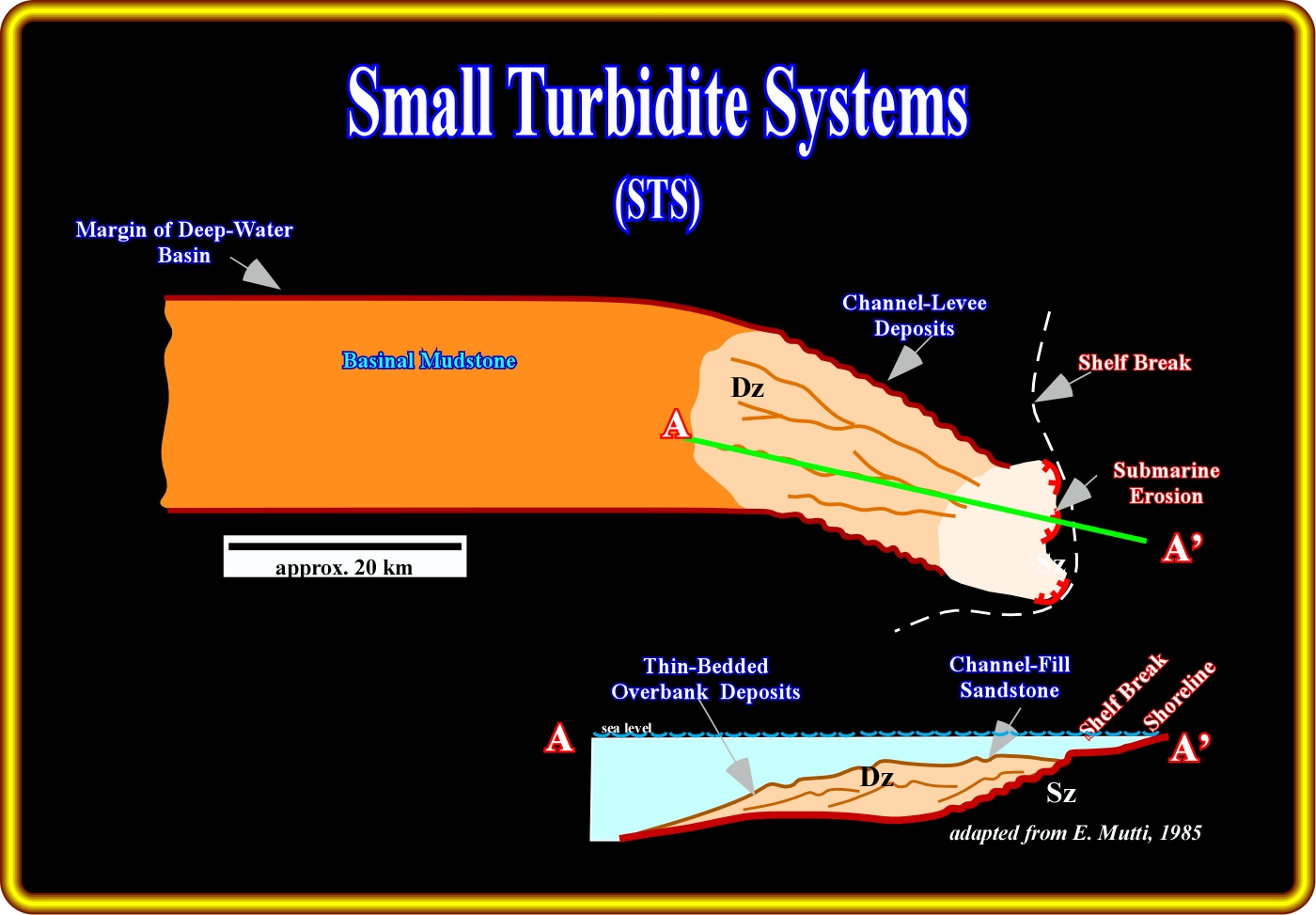
Small Turbidite Systems (STS) are characterized by small sandstone-filled channels that are enclosed by and grade down-current into predominantly muddy sequences. Channelized sandstone facies do not extend basinward and are therefore restricted to the inner portions of the systems. Channel-fill sequences are made up of fine to medium-grained sandstone in parallel-sided beds that characteristically thin and pinch-out toward both edges of the channel.
STSs develop in two main types of settings :
(i) In progradation phase of unconfined slope and
(ii) In confined settings during the late, retrogradational phase of infill of the canyons or SUVs (submarine valleys) associated with large or medium systems.
In the first case, they often pile up to build the slope and they may not be associated with any Large or Medium system. In fact, in a forestepping context, particularly when the basin has no platform, i.e. when the depositional coastal break is coincident with the shelf break, small turbidite systems develop in upper and middle slope. The facies is predominantly shaly with piling up of channel-levee complexes. The resulting seismic patterns are dominantly hummocky. Depending on the sand content in the sediment source (coastal /deltaic deposits), sandstone reservoirs can be developed. In favourable conditions, when a deltaic system is present, channelized sandstones can be deposited in the upper-slope; however they seldom extend basinward.
In West Africa offshore, and particularly in Cameroon offshore , small turbidite systems are quite well developed as illustrated below. Actually, below the Oligocene unconformity (SB. 30 Ma), in Cretaceous sedimentary packages, it is easy to recognize the “gull-wing” or mounded geometry of the seismic markers.
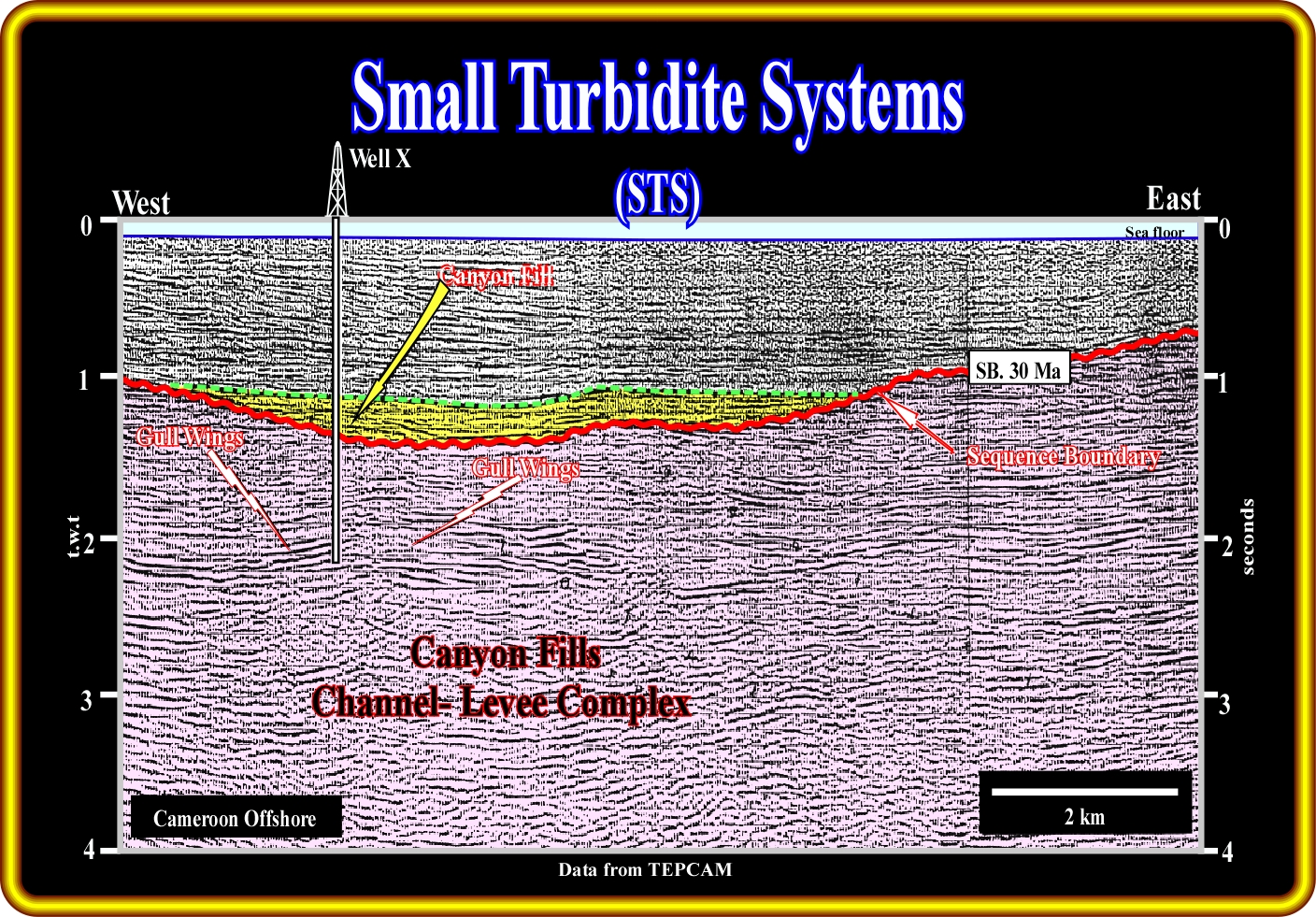
This seismic line shot in the conventional Cameroon offshore illustrates canyon fill and channel-levee complexes associated with small turbidite systems. Underlying the Oligocene submarine erosion (SB. 30 Ma) a thick channel-levee complex (small turbidite systems) has been recognized by all wells drilled in this offshore. Well results, such as Mutanda, Sulelaba, etc, have shown hydrocarbons in thin-bedded sandstones of over-bank deposits (levees). The reservoirs are too thin and too discontinuous to create economical hydrocarbon accumulations.
In the 70’s, such undulated geometry was interpreted as the result of sedimentary shortening and the majority of the wells were drilled to test structural traps. However, the well results strongly refuted the assumed structural geological model. Subsequently, a turbidite conjecture was advanced and the geometry explained by channel levee complexes. In the 80’s, the wells drilled corroborate the turbidite origin of the offshore deposits and a complex trapping mechanism (morphologic by juxtaposition / stratigraphic) :
- The reservoirs are mainly located in the overbank deposits (levees) ;
- They are too thin and too restrict ;
- They hardly reach 1 km of extension ;
- The turbidite channels are sinuous and filled by shales ;
- Hydrocarbons were found in almost all wells, however no economical accumulation was discovered.Confined Small Turbidite Systems are local, they are often the “proximal” expression of the retrogradation of Large or Medium Turbidite Systems. As a result, they often show a marked sequential character. The overall order of succession evolves from less evolved to more evolved resedimented deposits, in other words from debris flows to dilute turbidity currents (see later). Three successive packages were recognized :
- Lower package, which is dominated by depositional lobes deposited at the mouth of rectilinear or anastomosed channels ;
- Middle package, which is made up of rectilinear channel-fills ;
- Upper package, which is dominated by sinuous or meandering channels.
These kind of deposits can be illustrated by the filling of the Baudroie - Balliste submarine valley (SUV), in offshore Gabon (next plate), where, three different patterns can be recognized from bottom to top :
- Pattern A, which corresponds to a stacking of terminal lobes deposited at the mouth of rectilinear turbidite-channels ;
- Pattern B, which is interpreted as sandstones filling rectilinear channels and
- Pattern C, which marks the area of sinuous and meandering turbidite channels.
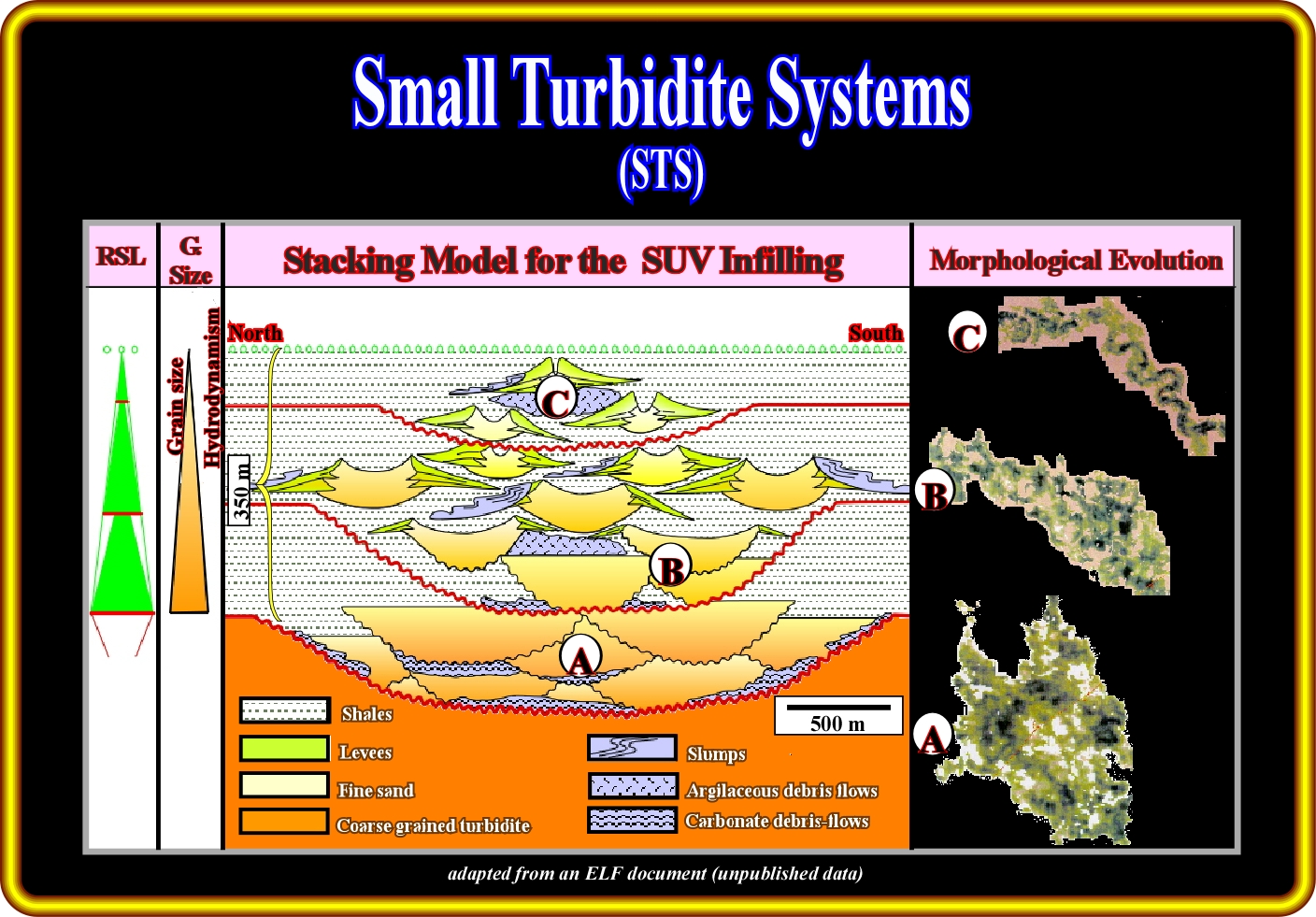
This schematic diagram depicts the fill of Baudroie-Baliste SUV (submarine valley), in offshore Gabon. From bottom to top three main patterns can be distinguished : (A) terminal lobes associated with rectilinear channels ; (B) Rectilinear channel fills and (C) Sinuous Channels.
Such a vertical succession displays a retrogradational pattern, which is correlative with a decrease in sand/shale ratio thickness interpreted from wireline logs. High amplitudes related to the infill of sinuous channels gradually develop up section. They are roughly correlative with a gradual decrease in channel width and sand/shale ratio.
B.3.1- Rectilinear Turbidite Channels
A seismic pattern often observed during the evolution of unconfined continental slopes is a succession (in map view) of bright “pods” linked by rectilinear channels. This pattern can develop in two ways:
(i) Minor changes in slope or (ii) Changes in sand content of the flows ;
(i) Slope irregularities can result in the succession of local sand traps (decrease in slope) and bypass zones. This phenomenon is very similar to the “fill and spill” mechanism proposed by Prather et al. (1998) for minibasins, but does not imply the existence of proper lows dammed by sills. A slight decrease in slope close to the depositional equilibrium is enough to slow down the flows, leading to sand deposition ;
(ii) The same pattern can result from temporal changes in sand content of the flows. Minor variations in the sand / mud ratio of the flows can modify the energy of the flows and their ability to build levees to constrain the next episodes.
Depending on the difference between the slope angle at the initiation of the system and the equilibrium slope angle (itself depending essentially on the volume and sand / mud content of the individual flows), sinuous channels can make minor isolated episodes of rapidly abandoned channels and lobes that are replaced laterally by rectilinear channels and lobes. Or, they may pile up to reach a thickness of several hundreds of meters.
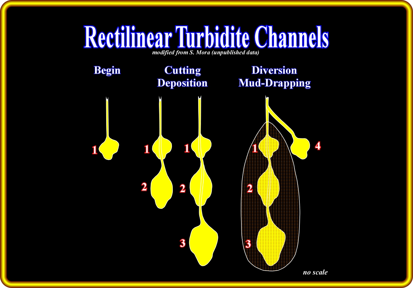
Very often in rectilinear turbidite channels three major phases can be considered : (i) Beginning phase, i.e., the initial phase, in which at the end a terminal lobe is deposited ; (ii) Cutting-Deposition phase, in which the last terminal lobe is partially eroded allowing a downward prolongation of the channel and finally (iii) Diversion Mud-Draping, when avulsion (change in turbidite current’s course) allows a mud-draping of the abandoned channel - lobe complex.
This association typically develops in continental slopes that are close to their equilibrium profile and devoid of a major sediment entry point (multiple source systems). The associated reservoirs are rather small and isolated, and their limited thickness does not allow easy recognition on 2D lines.
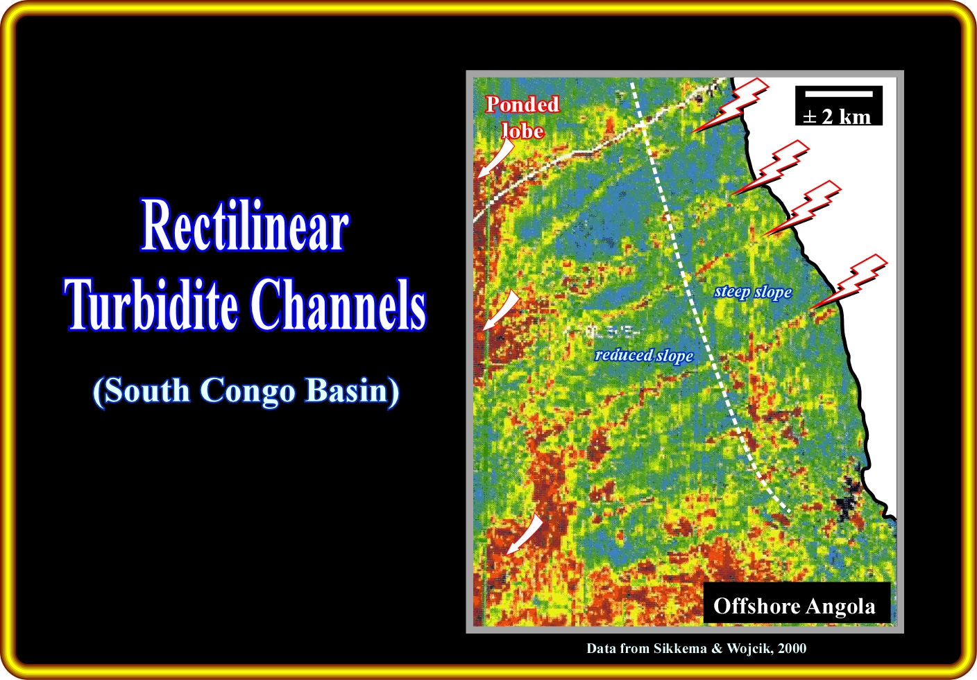
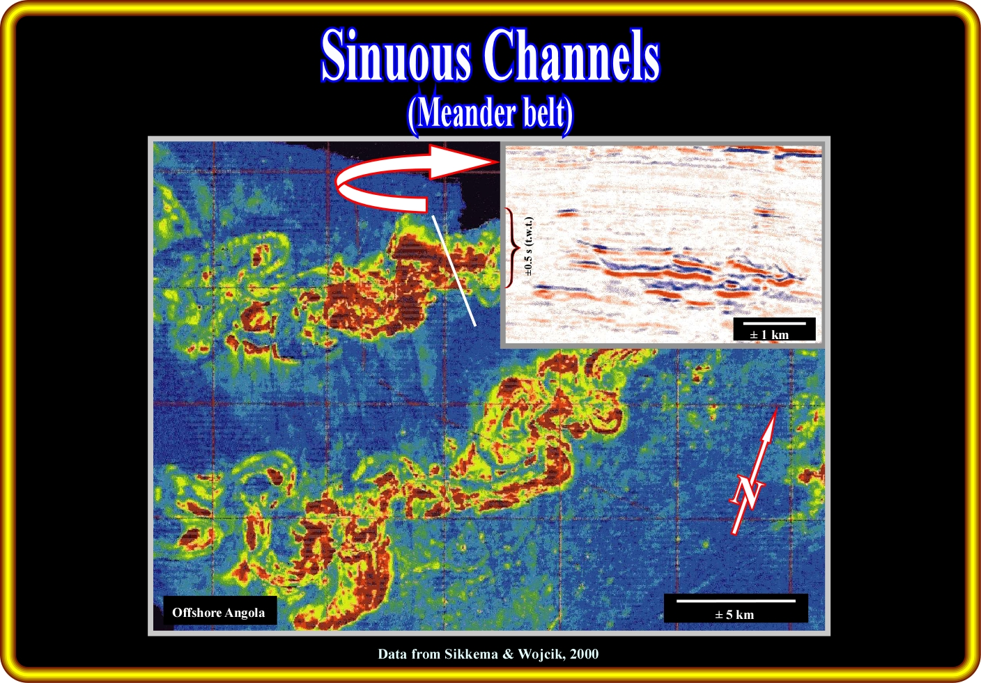
In offshore Angola, rectilinear turbidite channels occur on steep upper slopes. Notice that basinward, as soon as the slope is reduced, the channels became more sinuous and form branches that terminate in ponded lobes with channelized sand sheet reservoirs.
B.3.2- Sinuous Turbidite Channels
Isolated sinuous turbidite channels are usually identified by their characteristic pattern on amplitude slices of volumes of 3D seismic. In some cases, they are reasonably well imaged on 2D surveys, where one single line can image the same channel several times due to the sinuous nature of the channel.
Thick sinuous complexes appear to develop when slope equilibrium is re-established in an area previously starved and oversteepened by tectonic activity during the period of starvation, or oversteepened simply as a result of hemipelagite deposition during a period of starvation (oversteepening does not imply a precise angle, it corresponds to the contrast between the actual slope and the equilibrium slope of the system at issue).
We use here the term “sinuous channel” for turbidite systems in order to avoid confusion with meandering fluvial channels. Sinuous channels develop in turbidite environments, when the density of turbidity currents is just slightly higher than the density of seawater, i.e. the currents carry a very small amount of sand. Sinuous channel fills are often shaly. Meandering (fluvial) channels typically develop in low-grade fluvial plains and high amounts of sand are deposited as point bars in the inner bends of the channels while the outer bank is excavated. Notice that in classic sedimentology, a flow is sinuous when the ratio of sinuosity, (distance between two points following the flow versus the shortest distance between them), ranges between 1.5 and 2 and is meander-form when it is higher than 2.
Seismic amplitude responses sometimes suggest that some sinuous (turbidite) channels can be filled by sand. These would result from more complex histories, where the sand infill is not associated with the process that built the meanders, but by the passive infill in a later stage of meanders created during episodes of low activity.
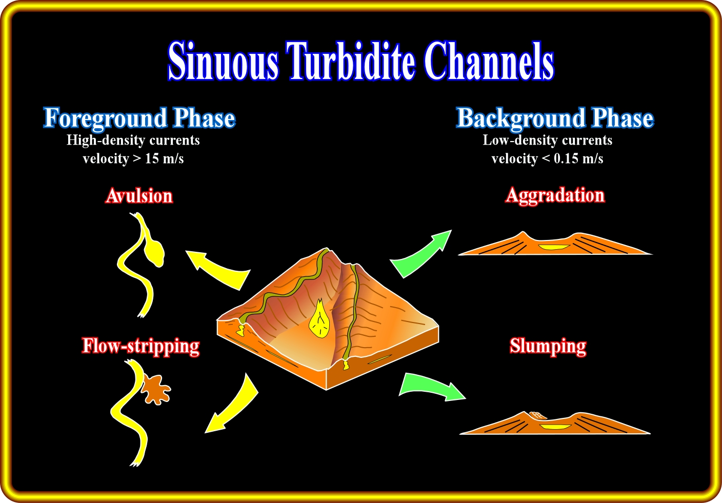
The avulsion mechanism, that is to say, a sudden cutting off or separation of land by an abrupt change in the course of the stream, in turbidite systems has been treated by Flood et al. 1991. Avulsion typically leads to a steepening in slope, with the new channel less sinuous than the old abandoned one. As the new channel progressively reestablishes equilibrium, its sinuosity increases to reach a maximum after which it essentially aggrades vertically.
Such complexes typically show the growth of a single channel over several hundreds of milliseconds (t.w.t.). The channel over that period of time usually shows a progressive increase from lower to higher sinuosity. Most of the time, a maximum sinuosity is reached after a while and pure aggradation occurs afterwards with progressive migration downslope (sweep).
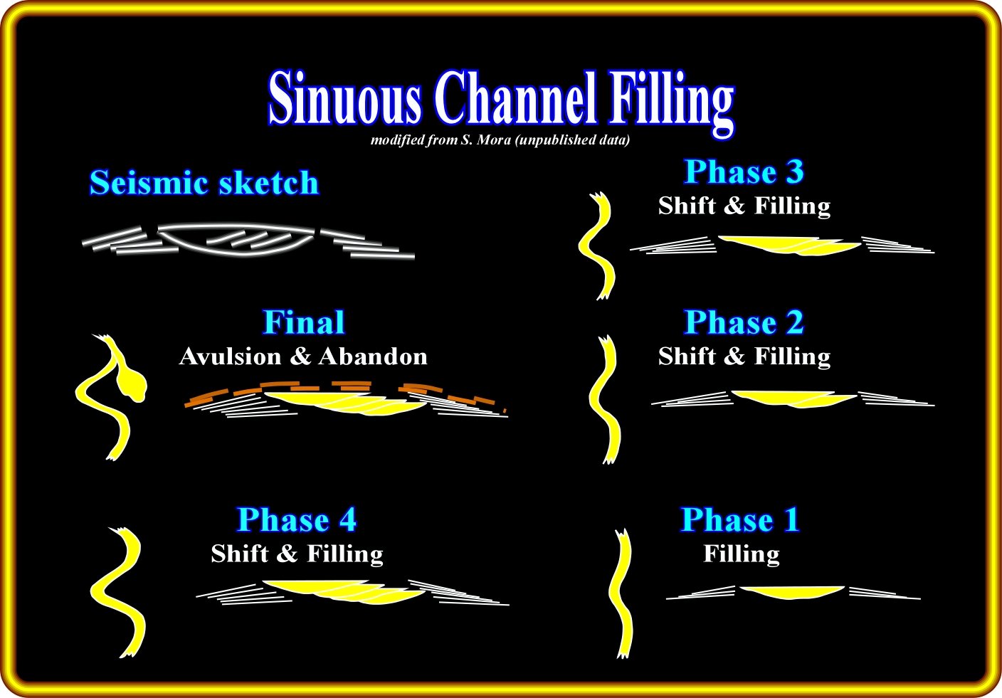
Contrary to fluvial meanders, which essentially get filled by progressive lateral accretion, turbidite sinuous channels typically get filled by successive episodes of cut and fill. Downcutting is interpreted to result from higher energy flows and produces sinuous lows, which are further filled up by retrogradational packages of turbidites. Like in fluvial meanders however, successive episodes of cut and fill migrate laterally towards the concave bank due to the curvature of the channel. Hence the similarity in the final geometry at seismic scale.
The main differences between fluvial and turbidite sinuous channels result from the difference in accommodation. Accommodation in fluvial systems is usually low, its rate of creation corresponding roughly to the subsidence of the area. On the other hand, accommodation in turbidite systems is best defined as the difference between the actual profile of the system and the “equilibrium profile” corresponding to the sediment supplied to the system (flow volume and sand / mud ratio). In many cases, accommodation for turbidite systems is very high, allowing high aggradation, whereas fluvial systems essentially migrate laterally. In other terms, the ratio between lateral migration and aggradation is high to very high in fluvial systems, and low in turbidite systems.

Sinuous turbidite channels are created by low-density currents, slumps or small high-density sand-rich turbidite flows. The bend evolution is characterized by an increase in amplitude and decline of wavelength with a lack of sweep and standstill of swing to attainment of channel stability. The channel evolution is characterized by strong aggradation, progressive reduction of length and depth, frequent avulsion, rare cut-off ridges and absence of swale topography. Fluvial meandering channels are created by bed load, suspensions and hyperconcentrated flow during flood events. Their bend evolution is characterized by an increase in amplitude and decline in wavelength, bend translation downstream (sweep) and laterally (swing) with repetition of bend sequence. The channel evolution is marked by a quick lateral migration, length and depth stability, frequent cut-offs, and development of ridge and swale topography.
Equilibrium profile is probably the main quantitative difference between fluvial and turbiditic “meander belts”. For comparison, the equilibrium slope of meandering rivers is in on the order of 1:10 000, that of turbidite “meanders” more commonly ranges between 1:100 (Rhone) and 1:1 000 (Indus) (see Clark and Pickering, 1996, for a compete review).
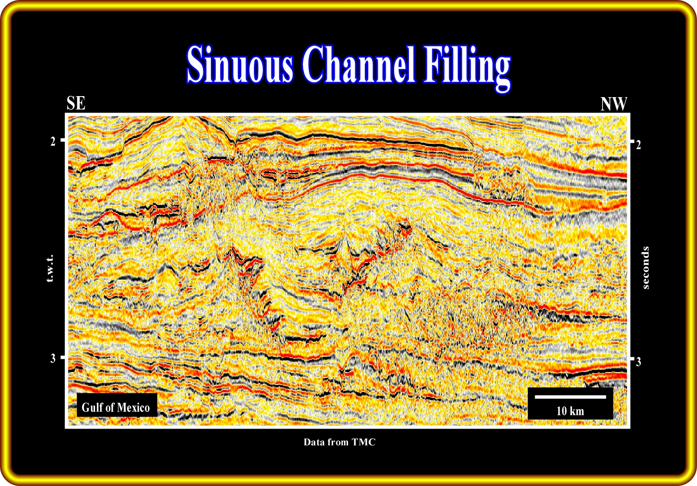
Two well-expressed channel-levee complexes in the deep Gulf of Mexico are shown above. The lower channel displays very clearly a succession of downcutting events followed by rather aggradational dominated fill. Both channels can easily be mapped, and are clearly highly sinuous in map view. Note that the migration is unidirectional for each channel complex, indicating that the lateral component of migration is predominant with respect to the downstream component.
The reservoirs of small turbidite systems include small lobes deposited at the termination of rectilinear channels, the proximal part of levees (proximal in relation to the channel with which they are associated), and the infill of channels, either rectilinear or meandering. As recognized in the Baudroie-Baliste small turbidite system (Gabon offshore), where from bottom to top three main patterns were distinguished in channel complexes: (A) terminal lobes associated with rectilinear channels, (B) rectilinear channel fills and (C) Sinuous Channels . A similar patterns occurs in the northern offshore of Angola (plate below).
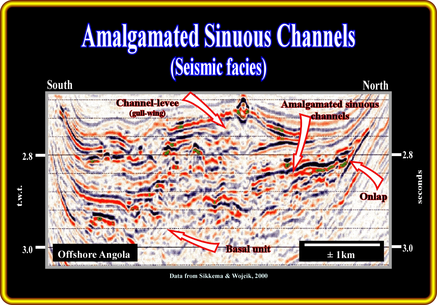
Shell geoscientists recognized similar turbidite facies within channel complexes of small turbidite systems first distinguished by Elf geologists in offshore Gabon. In fact, as illustrated on this close-up of a seismic line from deep water Angola (South Congo Basin), from bottom to top of the channel-complex, the following facies can be recognized : (i) A low-reflectivity chaotic facies dominated by sandy debris deposits ; (ii) High-reflectivity chaotic and semi-continuous facies with sinuous channels (in time slices, see plate below) dominated by amalgamated channel sands and (iii) gull-wing channel-levee at the top of the channel complex. The basal unit is dominated by clean, very poorly sorted debris sands, eventually with muddy debris flow deposits. These sandy debris flow deposits seem to be distributed as elongate lobes within the initial channel incision as suggested by certain time slices.
In this figure (for confidential reasons the scales and locations of the seismic line are quite approximate), the geometries of meander belt channel complexes are easily recognized. The northern complex, which is characterized by meanders, with less sinuosity, contain basal debrite sand deposits, which seem to correspond to elongate lobes within the initial channel incision, as illustrated below.
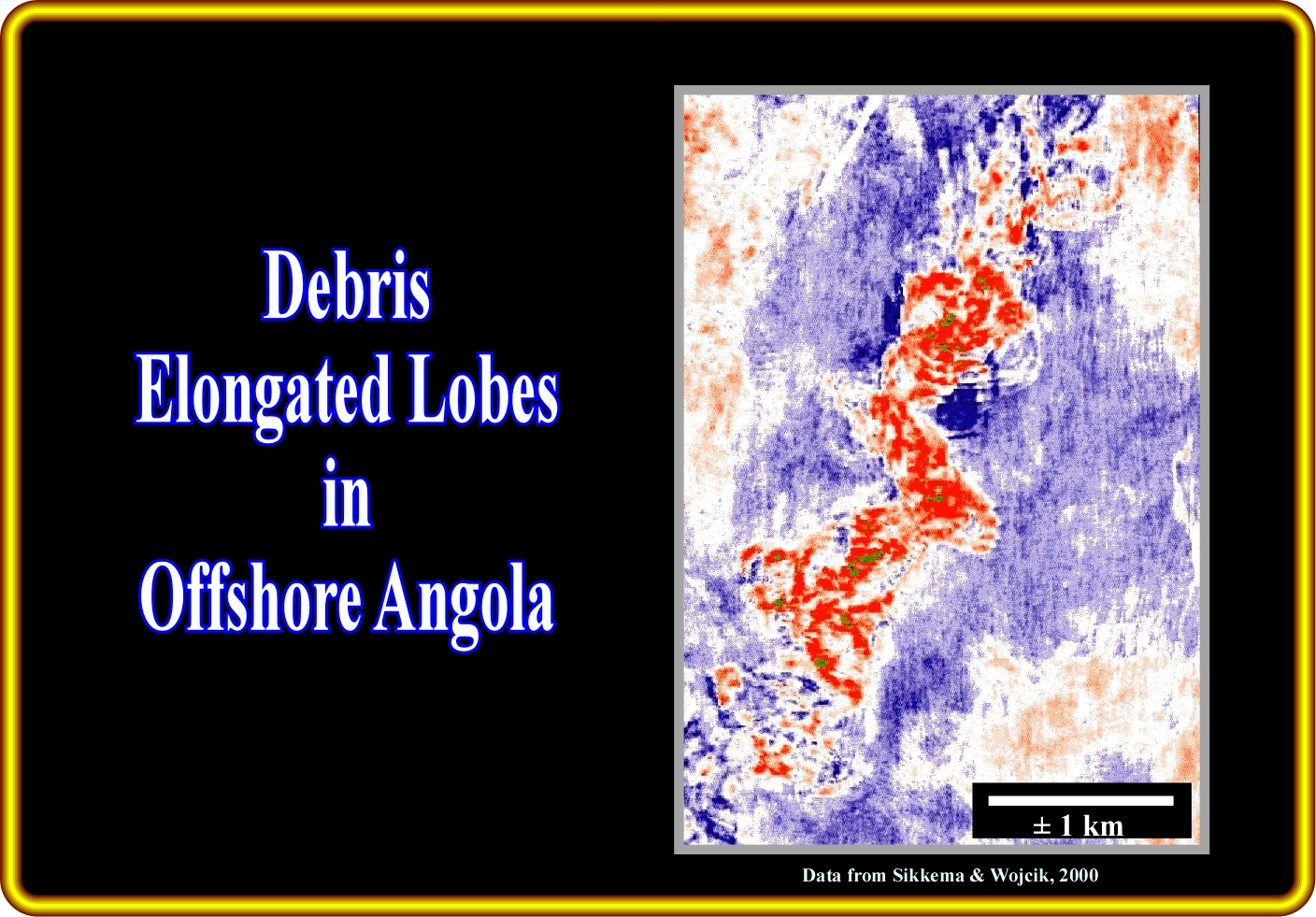
On this horizon time slice done at the base of an Oligocene channel complex from the northern Angola offshore, a seismic pattern characterizing debris-dominated elongated lobes filling the initial incision channel are illustrated.
Taking into account lateral migration, width-depth ratio, sinuosity, vertical aggradation and the rate of sand accumulation, Clark and Pickering (1996) proposed several potential channel complex patterns as illustrated below.
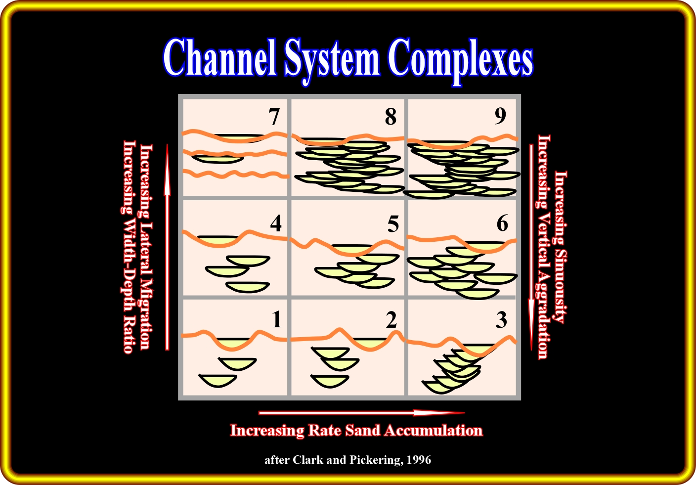
When in a submarine channel system, lateral migration and width-depth ratio are strong, sinuosity and vertical aggradation are low and rate of sand accumulation is high, the more likely pattern of the system, on the ground or on the seismic lines, looks like the one depicted in sktech 9.
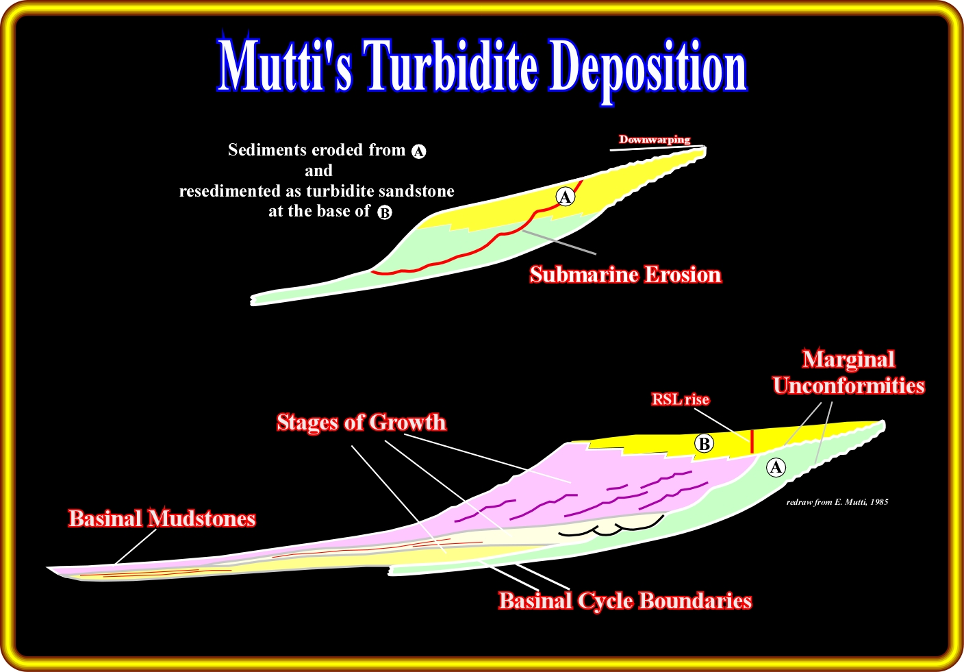
In the model of E. Mutti, the re-sedimentation process requires previous deposition of at least equal volumes of shelfal sands and muds at sufficiently high rates of sedimentation to prevent lithification. Such conditions are apparently met only in actively prograding deltaic systems that form during sufficiently long periods of highstand to allow the shelf to be loaded with thick intervals of unconsolidated sands and muds. Consequently, large-volume turbidite sandstone bodies have to be derived from adjacent shelfal areas that underwent phases of tectonic uplift or eustatic fall of sea level shortly after sufficiently long periods of highstand characterized by high rates of terrigeneous sedimentation. This hypothesis seems to be corroborated in Angola offshore where the larger recent worldwide hydrocarbon discoveries have been found.
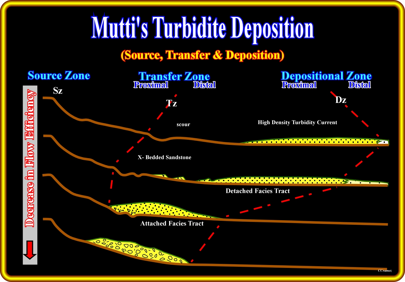
In their modern expression, both fluvial and turbidite systems have very obvious transfer zones characterized by a variety of channel patterns. In contrast, transfer zones are considerably less recorded, or recognizable, in ancient systems, where depositional zones are predominantly. Turbidite system grows through deposition by gravity flows sourced from the same source zone (commonly large-scale erosional features). The transfer zone can be defined as that portion of the basin along which the flow attains an equilibrium between erosion and deposition and can thus carry most of its sediment load farther basinward. The depositional zone is defined as that portion of the basin where the flow deposits the bulk of its load along a texturally graded profile. As illustrated above (adapted from Muttu, 1985) , source, transfer, and depositional zones of the gravity flow are related to flow efficiency.
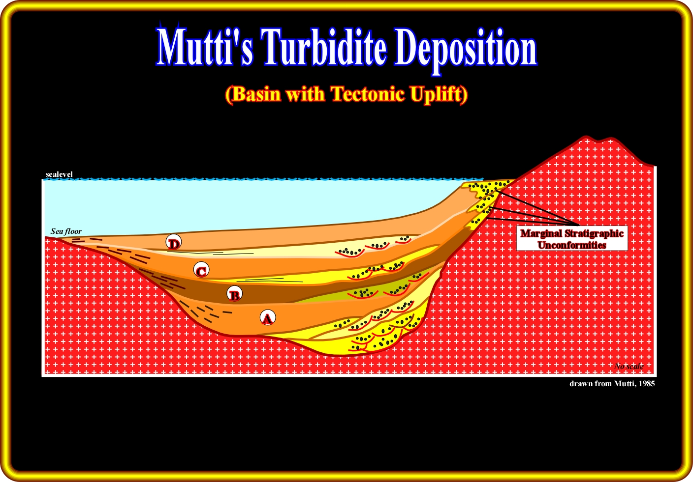
This turbidite geological model explaines quite well what one can observe on a basin with an important uplift of the proximal part of the basin. On this subject, geoscientists working in West Africa offshore, and particularly in Angola and Congo offshore, should not forget the regional Late Tertiary uplif of the continent an adjacent offshore areas, which in average is more than 2000 meters, when trying to explain the prolific turbidite reservoirs.
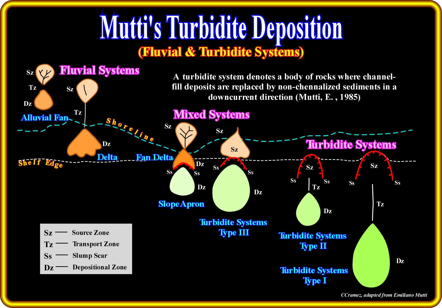
A turbidite system can be viewed simply as a fluvial system consisting of (i) a source zone - Sz, (ii) a sediments transfer zone - Tz, and (iii) a depositional zone - Dz. Mixed systems are those where gravity flows are more or less directly sourced by fluvial systems. Long-term global sea level variations and local tectonic control form the basic framework within which turbidite systems develop as a response to breaks in equilibrium between shelfal and basinal sedimentation.
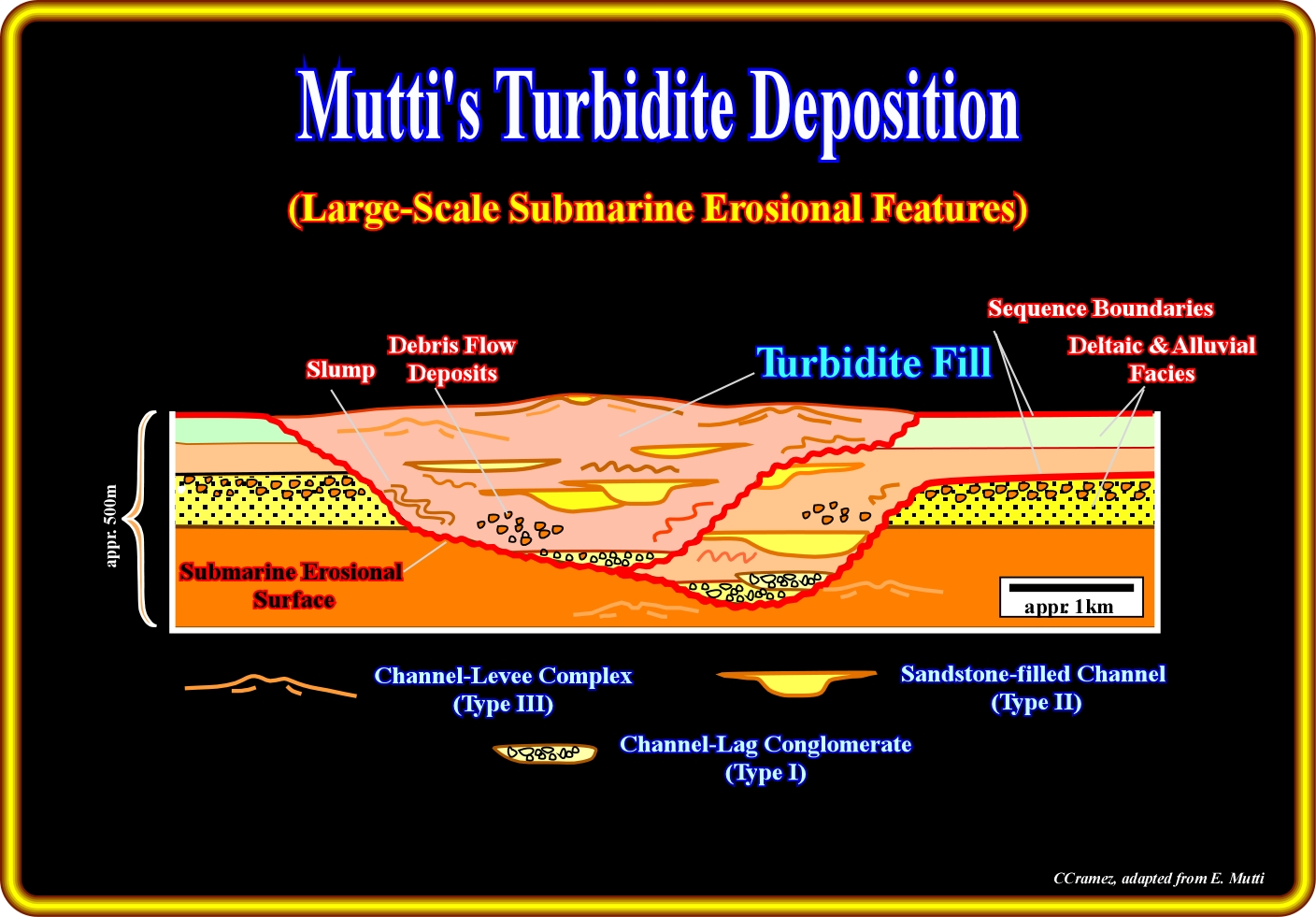
Upstream, large-scale submarine erosions cut the shelf sediments. They extend basinward as erosional features. They incise into slope and basinal thin-bedded mud-stones and sandstones. In their upper reaches, these large erosional features are filled with abundance of chaotic deposits. Down-current, the chaotic sediments become associated with and are gradually replaced by facies of thin-bedded turbidite mudstone and sandstone and lenticular bodies of sandstone and conglomerate. These coarse-grained facies are the in-filling of minor channels incised within the main erosional feature at different times during the evolution of the system. Very often, the decrease on flow efficiency induces the vertical superposition of the different turbidite systems. During the stage (turbidites Type I) most of the sand bypasses the channel region and accumulate in the outer and virtually flat basin. This implies that the sandstone of the lobes of such a systems are essentially physically detached from and not time equivalent to the channel-fill deposits.
to continue press
![]()
Send E-mail to carloscramez@gmail.com with critics, corrections or commentaries on these Turbidite Deposits notes.
Copyright © 2001CCramez
Last modification : November, 2013