
Universidade Fernando Pessoa
Porto, Portugal
Turbidite Systems
in
Hydrocarbon Exploration
Taking into account the possible causes of turbidite currents, it is utopic to advance a unique model for explaining turbidite deposits. Nevertheless, two chiefly turbidite geological models, proposed by Vail (1977, 1989, 1991) and Mutti (1977, 1992), explain the majority of the turbidite deposits, particularly those found in petroleum exploration. Vail's model (figs. 19 and 20) primarily explains turbidite deposits triggered by regional, or global, relative sea level falls, while Mutti's model (figs. 21, 22 and 23) explains those associated with large shelf-break slope slumps and catastrophic floods.
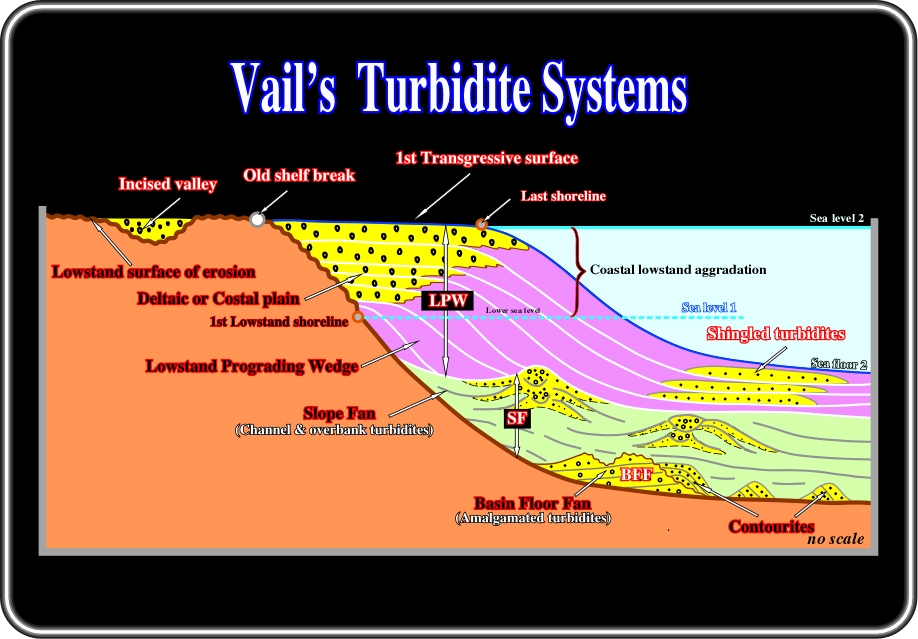
Fig. 19- In a deep-water setting, that is to say, when the limit between the shelf break, or the depositional coastal break, and the continental slope is well marked, Vail's turbidite model can be illustrated as depicted on this sketch. In fact, following a significant relative sea level fall (regional or global), the sea level descends below the shelf break and the platform is exhumed. Therefore, the basin has no more platform or shelf. The depositional coastal break (roughly the shoreline) is displaced seaward of the old shelf break, creating regional, or global, lowstand geological conditions. Such a displacement disrupts the equilibrium profile of the rivers, which are obliged to cut into the old sediments forming incised valleys in order to establish new equilibrium profiles. Such erosion created by relative sea level fall, substantially increases the terrigeneous influx. The sediments are discharged on the upper part of the continental slope and trigger turbidity currents which transport the sediments downward to the deeper parts of the basin where they are deposited as basin floor (BFF) or slope fans (SF). As relative sea level starts to rise, a lowstand prograding wedge (LPW) fossilizes the turbidite deposits. However, as the lowstand prograding wedge is deposited, instabilities on the upper slope, or catastrophic floods, can create significant slumps of sandprone material, which will be deposed at the toe of the lowstand progradations forming what geologists call shingled turbidites.
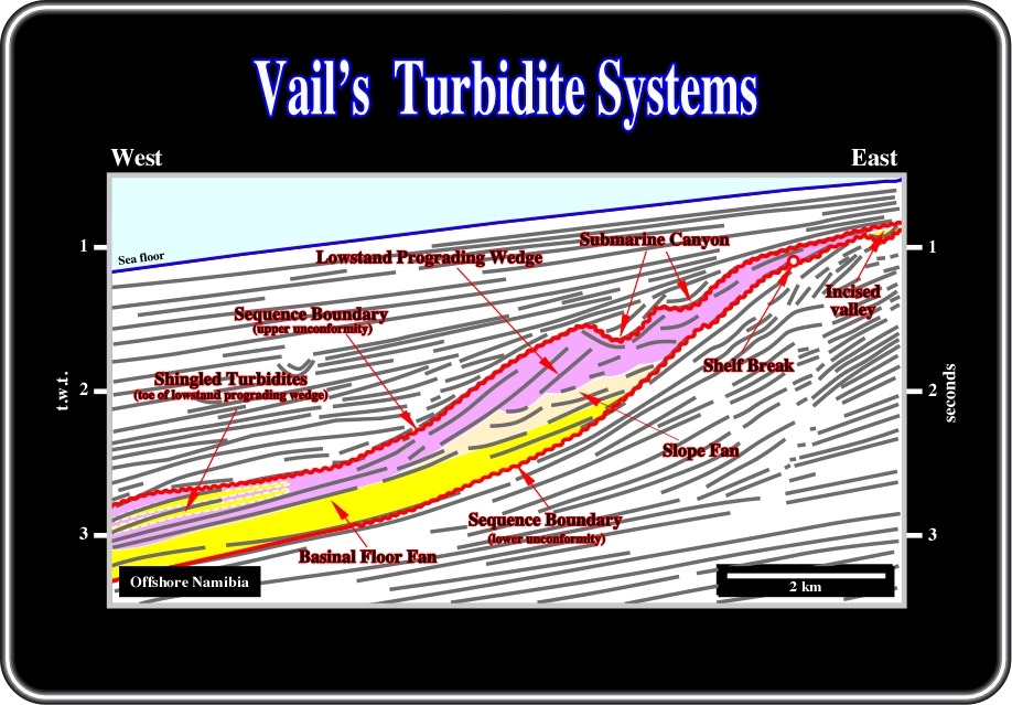
Fig. 20- Admittedly, tentative solutions of Namibia offshore seismic lines, using Vail's turbidite model (a priori hypothesis), are more difficult to refute than tentative solutions grounded on Mutti's models. In Vail's mode, eustasy and relative sea level falls are the major geological events that trigger turbidity currents and the associated depositional systems. Actually, as illustrated on this interpretation, between two consecutive relative sea level falls, two erosional surfaces, i.e., two unconformities (in red) were created. These erosional surfaces are underlined not only by reflection terminations but incised valleys as well. Indeed, following a relative sea level fall, the sea level dropped below the shelf break, obliging the rivers to incise their beds to reach new equilibrium profiles. On the other hand, between two relative sea levels falls, that is to say between two consecutive unconformities, as depicted, a 3rd order eustatic cycle (time duration between 0.5 My and 3-5 My) took place inducing a stratigraphic sequence-cycle. However, in this particular example, the sequence-cycle is incomplete. Indeed, just the lowstand systems tract was deposited. The transgressive and highstand systems tracts are absent. The three members composing the lowstand systems tract are easily recognized by the geometry and reflection terminations. From the bottom to top one can recognize: (i) Basin floor fan, (ii) Slope fan and (iii) Lowstand Prograding Wedge with its shingled turbidites. Conversely, the absence of obvious slope failures, coupled with a significant progradation of the shelf break with associated shelfal deposits apparently refutes the applicability of Mutti's models in this area.
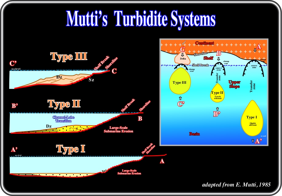
Fig. 21- In Mutti's turbidite systems, eustasy and relative sea level changes play an important role on turbidite deposition, but they are not essential for the development of the turbidite depositional systems. As pictured above, in Mutti's type II (B-B') and in type III (C-C') turbidite depositional systems, turbidite deposition takes place in highstand geological situation, i.e., when sea level cover the continental platform, which, in Vail's model is impossible. In fact, as said previously, in Vail's model (described later, in detail), turbiditic deposition requires a lowstand geological setting induced by a relative sea level fall, in which eustasy is predominant. One can say Mutti's type I turbidite depositional system is also developed in a geological context of highstand, as the basin has no platform. Actually, the shoreline and the shelf break are often coincident. In Mutti's models, the turbidity currents are mainly triggered by significant slumps, located near the limit between the upper slope and continental shelf) and slope failures, for type I and II. Striking progradation of the shelf break, associated often with catastrophic floods, is often the onset of turbidity currents in Mutti's type III systems. Subsequently, a source area (seaward of the slump scar) and a transfer zone are often recognized updip of major turbidite deposits.
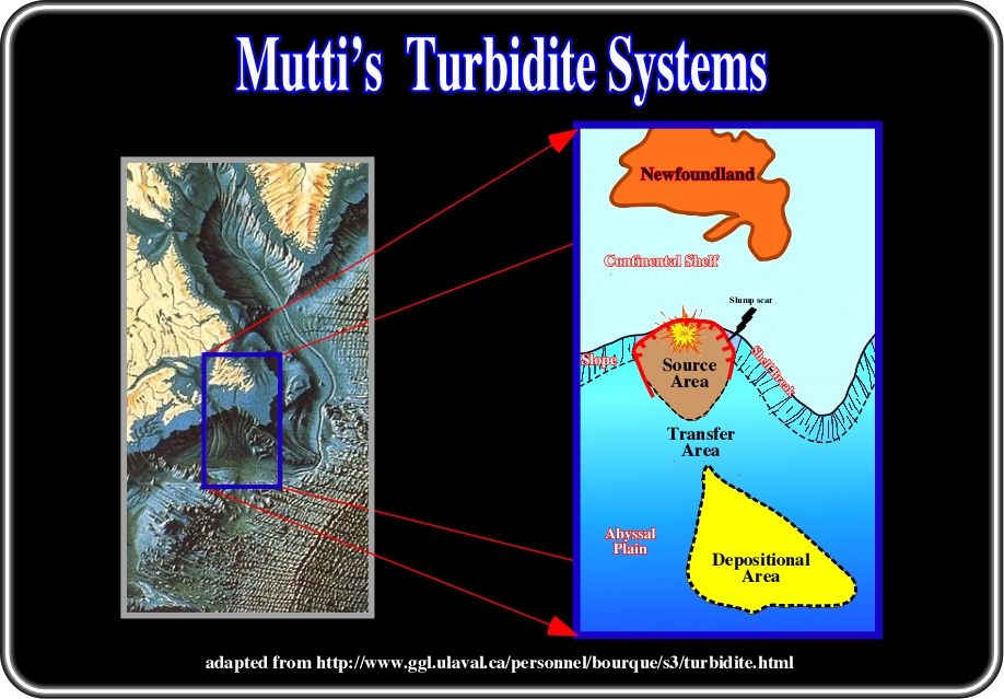
Fig. 22- In certain cases, as in the one illustrated here above, slope failures are so evident (here induced by an earthquake located near the shelf break) that abyssal plain sedimentary anomalies cannot be explained by a turbidite deposition associated with a relative sea level fall (Vail's model). Mutti's models (in this particular instance, type I system), better explain the sedimentary fan perceptible on the abyssal plain of the morphological map of the sea floor. Likely, as depicted on the tentative solution, a slump of great magnitude, probably induced by an earthquake, triggered a significant turbidite current. The transported sediments were deposited on the abyssal plain, since the current lost competence. Such a tentative solution is corroborated by the slump scar, the transfer area and geometry of the fan itself, which are recognized without difficulty on the morphological map. On the other hand, it is quite evident that such a slump, which happened on November 18, 1929 southward of Newfoundland (see fig 16), took place under highstand geological conditions, i.e., when sea level was above the shelf break. In other words, eustasy (Vail's model) did not played any role on the deposition of such a turbidite fan. Methodologically speaking, when a geologist recognizes, on the field or on seismic line data, a sedimentary anomaly on the continental slope or on the abyssal plain (it can be attached or not to the slope toe), he must put forward at least two tentative solutions, one based on Vail's model and the other grounded in Mutti's systems. Then, using all data available, he must criticize all tentative solutions and choos the less refutable, as illustrated in the next figure.
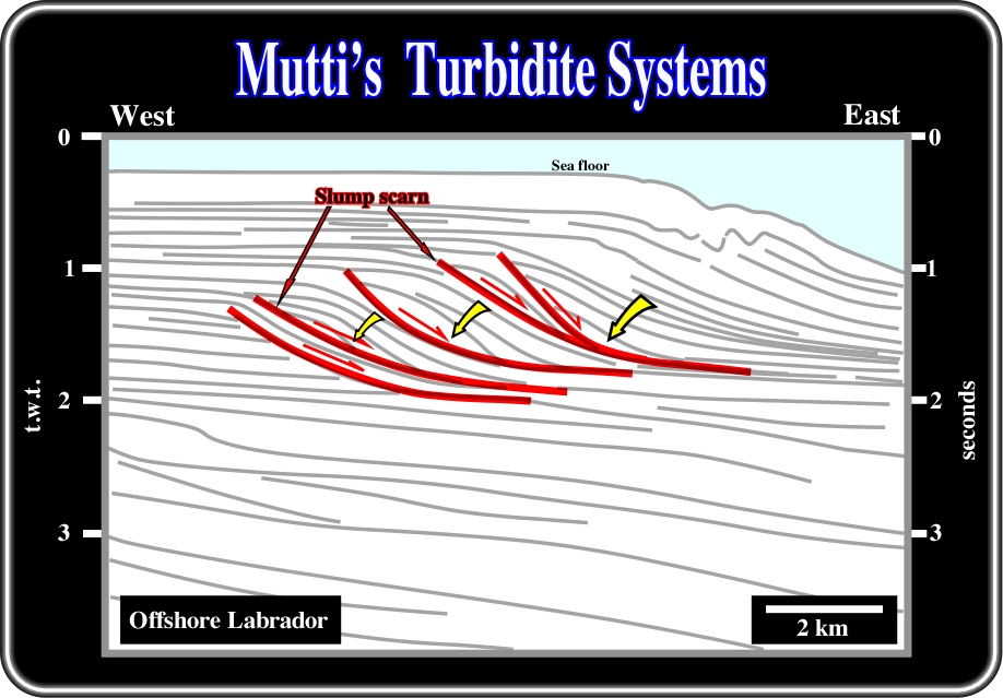
Fig. 23- This figure shows the interpretation of seismic reflectors and seismic surfaces (reflection terminations) of a seismic line from offshore Labrador. As said previously, theoretically, different tentative solutions can be put forward to explain the depicted geometry of seismic reflectors, particularly seaward of the shelf break. Such tentative solutions can be based either on Vail's model or Mutti's systems. However, those based on Vail's model does not resist a mild critical test. In fact, all along the coastal plain (subhorizontal reflectors continentward of the shelf breaks), there is no evidence of incised valleys and, in the upper slope, there is no evidence of canyons. In other words, between 0.9 and 1.9 seconds (t.w.t.), there is no evidence of a significant relative sea level fall. Therefore, the hypothesis of a continuous significant regression (forestepping) with catastrophic floods seems more likely. On the other hand, at five different time-periods, the continental slope is obviously underlined by strong seismic reflectors (under the red seismic surface interpretation), which look like slump scars suggesting gravity slumps triggered by catastrophic floods. In other words, taking into account the absence of evident regional erosional surfaces and the likelihood of large slumpings, the chosen tentative solution must be grounded in Mutti's models.
VI) Depositional Turbidite Systems
Depositional systems are defined as three-dimensional assemblages of lithofacies generally linked by active (modern) or inferred (ancient processes) environments (Fisher and MGowen, 1967). Note that the term lithofacies is here redundant. Indeed, facies was defined by Gressly (1835) as a lithology with a characteristic associated fauna. In depositional systems, facies are synchronous and genetically related. In other words, when a facies disappears, all others disappear too. In a deltaic system, for instance, there are three synchronous and genetically related facies: (i) the prodelta, (ii) the delta front and (iii) the delta plain. If the prodelta disappears, the other facies disappear too, i.e. the deltaic depositional system does not exist any more. In turbidite deposits, very often the depositional systems are not synchronous. For instance, bypass zones on the slope are common and so the final facies along the depositional profile are not coeval.
In Mutti's turbidite systems (Type II for instance), from the shelf break basinward, three main non-synchronous facies can be found. Mutti’s (1985): (i) Channel-fill thick-bedded sandstone, (ii) Thick-bedded sandstone lobes and (iii) Thin-bedded lobe fringes. However, if the thick-bedded sandstone lobes (ii) are not present, the others facies are not present either. They are more or less genetically related, and so the turbidite systems disappear.
In the literature there are numerous definitions for turbidite systems (Mutti & Normark, 1987; Mutti, 1992, etc.). Presently, the most used are:
A) A genetic unit, which records a series of genetically related erosional and depositional events that occurred in virtual stratigraphic continuity and are expressed by erosional and depositional elements respectively.
B) Depositional systems denoting bodies of rock where channel-fill deposits are replaced by non-channelized sediments in a down-current direction.
These definitions are generic and valid for a large spectrum of depositional systems (alluvial, deltaic, turbiditic, etc.). They do not define the stratigraphic character and the genetic significance of the boundary surfaces. Tentatively, we will propose to state the meaning of turbidite systems as:
“A succession of layers deposited by gravity currents which take place between two depositional equilibrium phases of the margins of the basin, whether marine or lacustrine”
Such a definition is faithful to Vail's model as well as to Mutti's systems. Indeed, a depositional equilibrium phase is a period of time during which the profile of the external platform-upper slope is stable (no sliding or collapse phenomena), and the sediment supply is not big enough relative to the size of the coastal area and/or the subsidence ratio, i.e., when any sediment is carried beyond the shelf break (deep water setting), or seaward of the limit of neritic-bathyal (ramp margin setting). The break-up of such equilibrium, by a relative sea level fall or by other geological features induces the formation of turbidity currents and subsequently turbidite systems:
- When the platform-upper slope profile is not stable, for instance, large slump-scars are created in the upper part of the slope. Then, they cut into the platform by headward erosion and eventually form canyons. At the same time, huge sandy turbidite fans will be deposited in the deeper part of the basin if the slope contains sufficient sand.
- When terrigeneous influx is too big for the accommodation on the shelf sand-rich turbidite fans will be deposited at the toe of the slope. Relative sea level falls create a similar geological situation. They decrease the size of shelfal accommodation.
Indeed, as said previously, the onset of turbidity currents (gravity flow), which carry sediments into deep water environments, can be related to sliding phenomena induced by: (i) overloading of sediments, (ii) earthquakes, (iii) halokinesis (salt tectonics), (iv) shalokinesis (shale tectonics), (v) fusion of hydrate layers, (vi) hyperpycnal flows (fig. 24), (vii) storm waves, (viii) tectonic movements, (ix) upwelling currents, etc., etc.
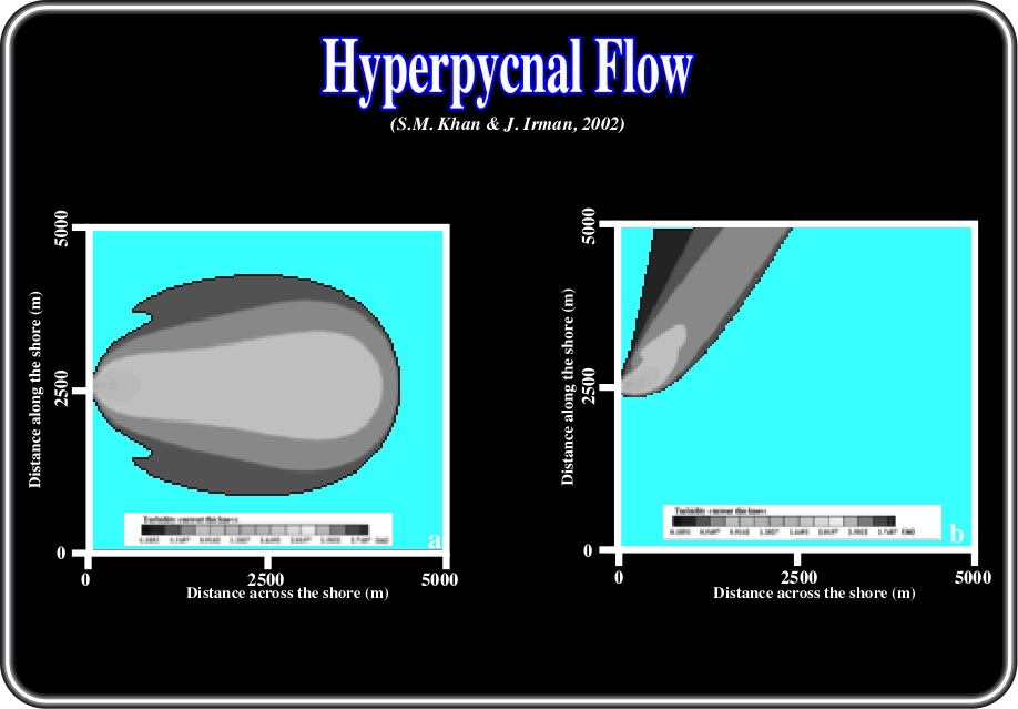
Fig 24- Hyperpycnal flows, that is to say, when the water entering a body of water is denser than the water that it enters, can often create turbidity currents. Its flow pattern is that of a plane jet as illustrated in the above simulated hyperpycnal flow (running during 4 hours) in the Adriatic Sea generated by plunging of the Potenza River: (a) no along-shore current and (b) with an alongshore current of 50 cm/s interacts with the hyperpycnal flow. Actually, in certain geological settings, the sedimentary flux to the sea can dramatically increase when climatic conditions provide sufficient amounts of water to produce catastrophic floods. These floods generate mixture of water and sediment that can enter sea water with sufficient velocity and sediment concentration to produce hyperpycnal flow (∂hf > ∂sw) and related, shelf-sustained turbidite currents.
In Mutti's systems, different geological factors control the geometry and facies distribution of turbidite systems (Mutti & Normak, 1987 and 1991). They can be grouped in two major families:
(i) The physiography of the platform, slope and abyssal plain.
(ii) The initial texture and lithological composition of the turbidity current and its evolution.
The first family (width and dip of the platform, dip of the slope, presence or not of mini-basins and/or canyons in the slope, trench basin or flat abyssal plain) is related to the geodynamic and tectonic evolution of the basin. The second one (gravel rich, sand rich, mud rich, siliciclastic or carbonate) is related to the depositional systems developed landward of the shelf break (carbonate platform, reefs, muddy estuary, braided-deltas, alluvial fans, etc.).
Theoretically, turbidite systems seem to correspond to large natural geological complex systems with many components to evolving into a poised, critical state, way out of balance, where minor disturbances may lead to catastrophic events. Turbidite systems can be taken as self-organized critically systems (SOC). In order to make this concept less abstract let’s describe the Bak’s sandpile model (fig. 25):

Fig. 25- The complex phenomena observed everywhere indicate nature operates at the self-organized critical state. The behaviour of the critical sandpile mimics several phenomena associated with complexity that can easily be observed across many sciences. This is particularly true for in geological sciences, where large catastrophic events such as turbidite systems, which cannot be understood within the set of references developed within the conventional scientific domains. The theory of complexity is able to explain such phenomena, at least partially.
Consider the scenario of a child at the beach letting sand trickle down to form a pile (fig. 25). At the beginning, the pile is flat, and the individual grains remain close to where they land. Their motion can be understood in terms of their physical properties. As the sand pile grows steeper, there will be little sand-slides. As time goes on, the sand slides becomes bigger and bigger. Eventually, some of the sand slides may even span over most of the pile. At that point, the systems is far out of balance, and its behaviour can no longer be understood in terms of the behaviour of the individual grains. These avalanches form a dynamic of their own, which can be understood only from a holistic description of the properties of the entire pile rather than from a reductionist description of individual grains: the sandpile is a complex system.
The sandpile is the canonical example of a Self-Organized Critical system (SOC). It exhibits punctuated equilibrium behaviour, where periods of stasis are interrupted by intermittent sand slides (as in turbidite systems). It can be expressed as a straight line on a double logarithmic plot, which indicates that the number of events is represented by a simple power law or logarithmic fractal (see fig. 14).
VII) - Turbidite Facies and Related Processes
A turbidite facies tract (FT) was defined by Mutti (1977, 1992) as the lateral association of genetic facies that can be observed within an individual bed or a package of strictly time-equivalent beds. Although facies tracts develop both in crosscurrent and along-current directions, lateral facies tracts refer primarily to facies changes that are observed in a direction parallel to the flow. The recognition of facies tracts suffers from two main limitations:
(i) The first is related to the fact that facies tracts can only be established within precise time-correlation patterns, i.e. within thin stratigraphic units that are physically traceable over significant areas.
(ii) The second limitation is represented by the very low-gradient facies variations that most systems undergo over the available outcrop areas.
In terms of facies, Walker (1984) considered a set of sedimentary features characterizing the classical turbidite deposits, as follows:
1- Sandstones and shales are monotonously interbedded through many tens or hundred of meters of stratigraphic sections. Beds tend to have flat tops and bottoms, with no scouring and channeling on a scale greater than a few centimetres.
2) Sandstones beds have sharp, abrupt bases, and tend to grade upward into finer sand, silt and mud. Much of the mud was brought into the basin by the turbidity current (it contains a shallow water transported faunal assemblage), but the uppermost very fine clay may contain a bathyal or abyssal benthonic fauna and hence represent slow hemipelagic deposition between turbidity current events.
3) On the undersurface (sole) of the sandstone beds there are abundant markings, now classified into three types. Tool marks carved into the underlying mud by rigid objects /sticks, stones) in the turbidity current; scour marks cut into the underlying muds by fluid scour; and organic markings representing trails and burrows filled by the turbidite current. Tool and scour marks give accurate indications of local paleoflow directions, and by now, many thousands have been measured to reconstruct paleoflow patterns in hundreds of turbidite basins.
4) Within the sandstone beds, combinations of parallel lamination, ripple cross lamination, climbing ripple cross lamination, convolute lamination and graded bedding have been noted by many authors.
An ideal, or generalized succession (or sequence) of facies was proposed by Bouma (1962), and the Bouma sequence, illustrated in fig. 26, can be regarded as an excellent facies model for classical turbidites, that is to say, those which consist of monotonous alternations of sandstones and shales, parallel bedded without significant scouring or channeling and where all the beds can reasonably be described using the Bouma sequence (fig. 27). This classical model seems to fit better with those gravity flows associated with significant relative sea level falls (Vail's model).

Fig. 26- In a complete Bouma sequence, five divisions can be considered: A) massive or graded, B) Sandy parallel laminations, C) Rippled and /or convoluted, D) Delicate parallel interlaminations of silt and mud and E) Mud introduced by the turbidity current and hemipelagic background mud of the basin. As illustrated in the lower part of the figure, the organization of a turbidite sequence changes with its position in the fan and so with the velocity of the current. Up-dip, facies A are those of debris flows; facies B, quite rich in sand like those of traction currents; facies C is the classic turbidite with a complete Bouma sequence (a-b-c-d-e); facies D, rich in thin beds, quite developed bottom-truncated Bouma sequence (b-c-d-e, c-d-e or d-e). In the fringes (lower fans), the sediments are thin. They are often reworked by sea floor current, which following continent contours are called contour currents. The reworked sediments exhibit current ripples and forms, and are called contourites by geologists (see figs. 19).
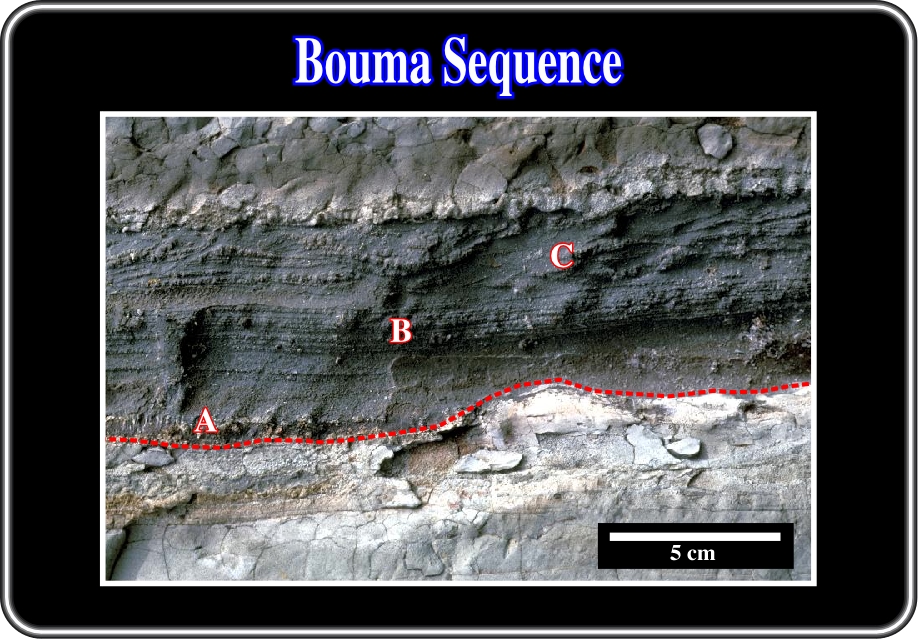
Fig. 27- A complete Bouma sequence, as illustrated in fig. 26, begins with a graded division A, which is overlain by parallel laminated division B and cross-laminated division C. In this example facies D and E are very thin, due to erosion or non-deposition. Indeed, as said previously, bottom sea currents often erode the upper divisions.
On a small scale, the Bouma sequence works quite well as a facies model for classical turbidites. However, as pointed out by Walker (1984) there are other turbidite facies that are not characterized by Bouma sequences, as (i) massive sandstones, (ii) pebbly sandstones, (iii) conglomerates and (iv) slumps, slides, debris flows and other exotic facies.
It is interesting to notice that the turbidite system was the first in which a universal facies scheme was proposed by Mutti and Ricci Luchi (1972). The Mutti and Ricci Luchi scheme (fig. 28) has been modified over the years.
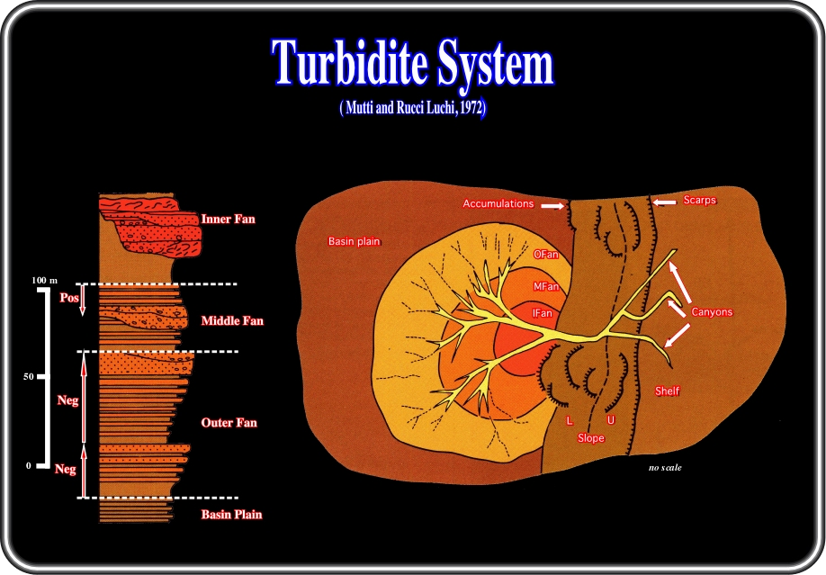
Fig. 28- This figure illustrates the fan model of Mutti and Ricci Luchi, in which (U) is the upper slope, (L) the lower lope slope environments and (IF) is the inner, (MF) the middle and (OF) the outer fan. The log represents a hypothetical sequence formed during a fan progradation, in which "positive" (Pos) and "negative" (Neg) facies sequence as distinguished. "Positive"denotes thinning- and fining-upward channel-fill deposits and "negative" denotes thickening- and coarsening-upward progradational depositional lobes.
Facies tracts can only be significantly reconstructed within a framework for predictive facies classification scheme that relates facies and processes, i.e., through the second, or genetic, level of facies analysis. Such a framework, proposed by Mutti (1977, 1992), is illustrated in fig. 29, and covers a very broad spectrum of facies from cohesive debris flow deposits (F1), with boulder-, cobble-, and pebble-sized clasts, to graded mudstones (Te of F9a).
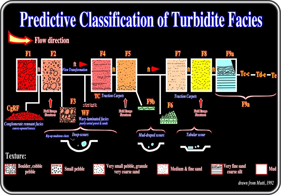
Fig. 29- Four kinds of flow transformations were recognized by Mutti in 1977 & 1992. (i) Body transformation occurs when the flow changes between laminar and turbulent within the body of a flow without significant addition or loss of interstitial fluid; (ii) Gravity transformation occurs when initially turbulent, particle-charged flows become gravitationally segregated and develop a high concentration, laminar underflow with an overriding more dilute turbulent flow; (iii) Surface transformation occurs when ambient fluid becomes mixed or lost at flow boundaries by drag over separation into laminar and turbulent flow; (iv) Elutriation transformation develops by elutriation of the particles by upward-moving fluids from a high-concentration flow to produce a turbulent dilute-phase above the base of the flow (elutriation is a purification, or removal of material from a mixture or in suspension in water, by washing and decanting, leaving the heavier particles behind).
Direct field evidence shows that cohesive debris flows; hyperconcentrated flows, and gravelly, high-density turbidity currents produce facies types, which are clearly genetically inter-related. The main facies types can be subdivided into three main groups:
A) Very Coarse Grained Facies,
B) Coarse Grained Facies,
C) Fine Grained Facies
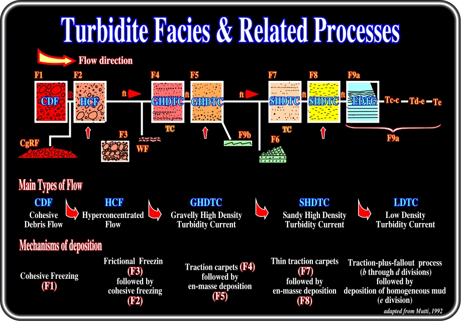
Fig. 30- In cohesive debris flows, clasts are supported by matrix strength and density, and deposition takes place when the applied shear can no longer overcome the flow strength. Sediments of this type, which result from cohesive freezing, are easily recognized since they consist of mud- supported clast. In high-density turbidity currents, either gravelly or sandy, clasts are supported within the flow by several mechanisms, which are inherent to sediment concentration and in which result in hindered settling of coarse particles. The sediments of these flows typically consist of thick-bedded and coarse-grained sandstone and pebbly sandstone facies. Low-density turbidity currents characteristically maintain their fine-grained sediment load within the flow through turbulence and deposit it through a very distinctive process of traction-plus-fallout. Beds in which thoroughly current-laminated fine-grained sandstone and coarse siltstone grade upward into a massive mudstone unit commonly represent these sediments.
1) Very Coarse Grained Facies
Three main facies can often be distinguished:
F1 deposits (figs. 29 and 30) are the product of cohesive debris flows. The following features characterize them:
- The lack of significant basal scours.
- The larger clasts floating in a matrix, which relative to the F2 deposits of the same facies tract, is muddier and may show features related to plastic flow.
- The tendency for the largest clasts to concentrate toward the top of the bed and project upward above the top of the bed.
F2 deposits (figs. 29 and 30) are considered as the product of hyperconcentrated flows resulting from the downslope transformation of cohesive flow through progressive mixing with ambient fluid. F2 deposits are extremely common in many coarse-grained turbidite systems. Relatively to the F1, the following features characterize them:
- Occurrence of deep basal scours and large rip-up mudstone clasts.
- The larger clasts float in a fully mixed and occasionally crudely graded matrix composed of mud, sand and gravel.
- The largest clasts show a clear tendency to occur in the lower part of the bed.
F3 deposits (figs. 29 and 30) consist of clast-supported conglomerates forming beds and bedsets commonly bounded by basal erosional surfaces. The internal organization of this facies is variable and is most commonly represented by an unstratified and generally inversely graded deposit. This organization strictly depends on the shear stress imparted on these gravel layers from the overlying residual flow.
B) Coarse Grained Facies
This group includes, in a downcurrent direction, WF, F4, F5, and F6 (figs. 29 and 30) sediments, which are interpreted as products of gravelly, high-density turbidity currents and of the transformations which take place from the origin to the end of these flows:
- WF sediments (figs. 29 and 30) consist of relatively thin divisions, usually between 5-20 cm thick, of very poorly sorted very coarse sand and small gravel beds displaying a faint wavy lamination. Wavelength is generally less than 50 cm and individual laminae have a thickness up to 1cm. These sediments have been tentatively interpreted as an upper flow regime, which forms at the transformation of a hyperconcentrated flow into a fluidal, high-density, and supercritical turbidity current.
- F4 and F5 deposits (figs. 29 and 30) are the most common sediments found within this group of facies. Relatively thick and coarse-grained traction carpets characterize F4 deposits.
- F5 deposits (figs. 29 and 30) are devoid of internal stratification and fluid escape features can be very common. Unless the original parent flow already consisted of relatively well-sorted sediment, F5 beds are characteristically poorly sorted compared with to F8 deposits.
- Coarse-grained and internally stratified deposits represent F6 sediments (figs. 29 and 30). These beds are generally relatively well sorted and characterized by the common lack of grading. These sediments are considered as a product of a hydraulic jump that transforms a supercritical high-density turbidity current into a subcritical, low-density one.
C) Fine Grained Facies
This group includes F7, F8 and F9 deposits, i.e., those sediments that are considered as the product of low-density, sub critical turbidite currents (figs. 29 and 30). These currents begin their deposition after either a hydraulic jump (F6) or a gravity transformation through which an F5 deposit is overlain or replaced in a down current direction by an F7 deposit. The end of the deposition is reached where the mud-size suspended load can settle through a quasi-static flow. These fine-grained facies are generally considered the best-known turbidite sediments since they include the classic Bouma sequence and the classic turbidite of Walker.
- F7 deposits (figs. 29 and 30) are common in many turbidite systems and are characterized by thin and relatively coarse-grained, horizontal laminae that can be easily mistaken for the traction carpets of F4 deposits or the b Bouma division of F9 beds.
- F8 sediments (figs. 29 and 30) are considered as the true division a of the Bouma sequence and consist of structureless, medium to fine sand. Grading may or may not be present. Within the same facies tract, an F8 division is always finer grained and considerably better sorted than an F5 deposit, thus permitting an easy distinction between the two facies types.
- F9 deposits (figs. 29 and 30) are made up of thoroughly current-laminated divisions of very fine sand and coarse siltstone which are capped by a massive mudstone division, These sediments, which are commonly referred to in most literature as “base-missing” Bouma sequences (Tb-e, Tc-e, Td-e and Te sequences), constitute the volumetrically most important component of many ancient turbidite basin-fills. F9 strata can be simply defined as turbidite beds, which have been deposited by traction-plus-fallout processes, associated with the various stages of sedimentation of waning low-density turbidity currents.
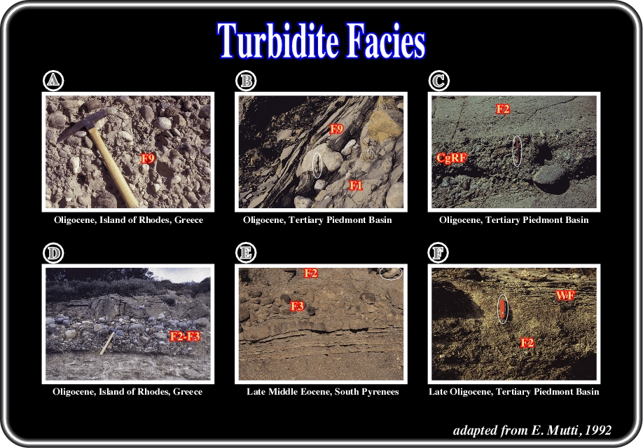
Fig. 31- A) Thick pebbly mudstone (F1) containing out-size blocks of a slump-folded sandstone in its upper part (no shown in photograph). These blocks were transported within a "rigid plug" of cohesive debris flow, i.e., where the applied shears stress cannot overcome the internal strength of the flow. B) Laminated sandstone (F9 deposit) onlaps onto and drapes a large clast of F1 deposit. C) Abrupt and probably erosional contact between the CgRF and the overlying F2 deposit.The CgRF is interpreted as the result of a surface transformation of a cohesive debris flow whose upper part has been transformation into a hyperconcentrated flow. D) Basal inverted graded and very poorly sorted clast- to sand. supported cobble and pebble conglomerate overlain by a structureless sandstone containing floating cobbles and pebbles at different levels.This bed is interpreted as the result of both frictional and cohesive freezing that occurred during gravity transformation within an hyperconcentrated flow. The bed is therefore classified as an intermediate deposit between F2 and F3. E) Gravity transformation of a hyperconcentrated flow has produced a basal F3 deposit overlain by a F2 division. Note the abrupt wedging of the F3 deposit toward the right, i.e. in an upcurrent direction. F) Poorly shorted and crudely graded sandstone (F2) overlain by a WF facies. The latter consists of irregular undulating laminae of coarse-grained sandstone with scattered small pebbles. The facies is thought to record a surface transformation from an underlying hyperconcentrated flow into a supercritical fluidal flow.
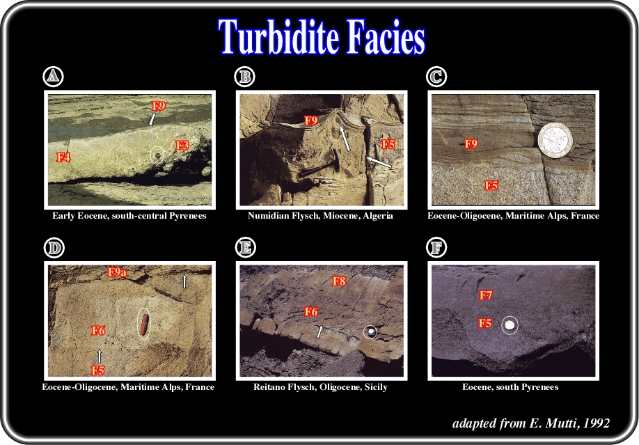
Fig.32- A) Bed showing a very abrupt facies change between F3 and F4 divisions. On the right, the basal part of the F3 division includes abundant rip-up mudstone clasts. A thin , F9 division forms the top of the bed, draping both F4 and F3 deposits. B) Water-escape feature (arrow) developed in F9 laminae overlying a F5 division. Younging direction is to the left. C) F5 division abruptly overlain, through a break in grain size, by a thin F9 division. The latter is interpreted as the deposit of the dilute "tail" of the flow. D) From base to top, the bed consists of a basal F5 division abruptly overlain by an F6 deposit with cross stratification. The F6 division is sharply overlain by an F9a deposit showing ripple and convolute lamination. Both sharp contacts (arrows) are thought to record sediment bypass. E) Two amalgamated sandstone beds (arrows indicates the amalgamation surface). The upper bed consists of a lower division made up of very coarse-grained and cross stratified sandstone (F6) overlain, through a sharp break in grain size, by and F8 division composed of medium-to fine-grained structureless sandstone. F) Composite sandstone bed characterized by a basal, poorly sorted F5 division overlain by an F7 deposit with thin to very thin traction carpets. Note the lack of an F6 deposit between the two facies and the fairly distinct break in grain size between F5 and F7 divisions.
to continue press
next
![]()