
Universidade Fernando Pessoa
Porto, Portugal
Turbidite Systems
in
Hydrocarbon Exploration
VIII) Turbidite Systems Classification
Taking into account the causes of turbidite currents, it is utopic to propose an unique model to explain the turbidite deposits. However, two chiefly turbidite geological models, proposed by Vail (1977, 1989, 1991) and Mutti (1977, 1992), explain the majority of the turbidite deposits found in petroleum exploration. Vail's model (fig. 18) explains primarily the turbidite deposits triggered by regional, or global, relative sea level falls, while Mutti's model (fig. 20) explaining those associated mainly with slope failures and catastrophic floods.
In these notes, what we call Vail's model for turbidites, in opposition to Mutti's systems, is part of the sequence stratigraphy approach proposed by the Exxon team in the 70s and 80s. In fact, in sequence stratigraphy the major factor driving the cyclicity of the sedimentary deposits is, among others (subsidence, terrigeneous influx, climate) eustasy, i.e., sea-level changes. Such conjecture, which was previously advanced by: (i) De Maillet, 1748, (ii) Lavoisier, M., 1793, Lemoine, 1911, Burollet, P.F., 1954, etc. etc.), is corroborated by the recognition and mapping, on the ground and seismic lines, of stratigraphic intervals bounded by unconformities. That is to say, limited by erosional surfaces formed primarily in response to an increase in the rate of sea-level fall or to a decrease in the rate of subsidence
A.1) Sequential Stratigraphy Review
Eustatic unconformities, which are relatively insensitive to sediment supply, are correlative, or nearly correlative, in all basins connected with the open ocean. This is also independent of the rate of subsidence or sediment supply in a given basin, whether sea-level varies rapidly or at rates comparable to typical rates of tectonic subsidence (not all geologists agree with such conjectures). Subsequently, they have been used to define the four chief types of stratigraphic cycles (fig. 33) composing the stratigraphic records (Duval, B., et al. 1993):
1) Continental encroachment cycles,
2) Continental encroachment sub-cycles,
3) Sequence-cycles, and
4) Parasequence-cycles.
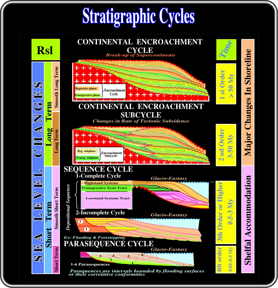
Fig. 33- The limits bounding these stratigraphic intervals are unconformities. As pointed out previously, and as illustrated on the above hierarchy, in these notes, we will restrict the term sequence to sequence-cycle, i.e., the stratigraphic cycle developed during a 3rd order eustatic cycle, which Exxon's geologists characterized by a time duration ranging between 0.5 and 3-5 My. In this stratigraphic cycle classification, the Exxon terms supersequence and megasequence were discarded to avoid misinterpretation. Indeed, a supersequence, or a megasequence, is not a sequence with outstanding qualities or an exceptionally large sequence.
1) Continental Encroachment Cycles (fig. 33)
These cycles are associated with 1st order eustatic cycles. They are characterized by a succession of coastal onlap against the cratons. They fossilize the unconformity created by the formation of Supercontinents. Two continental encroachment cycles have been deposited since the beginning of the Phanerozoic
(a) The Palaeozoic cycle
(b) The Ceno-Mesozoic cycleBoth are recognizable in all continents. They are believed to be global. Assuming the Latest Proterozoic represents the time of slow encroachment with regression, we can say that during the Paleozoic cycle:
- Cambrian represents the time of extensive encroachment with transgression.
- Ordovician represents the eustatic high.
- Silurian to Permian represents the time of restriction.
Similarly, during the Meso-Cenozoic encroachment stratigraphic cycle one can say:
- Triassic represents a time of gradual encroachment of sediments onto the craton. Greatest thickness of non-marine sediments was deposited in grabens (rift-type basins) and bordering marine basins. This general pattern is believed to be caused by a slow relative rise of sea level due to slow long-term rise in eustasy. Non-marine rocks were widespread because the sediment supply exceeded the space being created by slow relative rise, resulting in major regression.
- Jurassic and Lower Cretaceous represent times of extensive encroachment of sediments on to the continental margins. These sediments are predominantly marine. During this time period, the average relative sea level rose more rapidly due to an increase in the rate of rise of long-term eustasy. Marine rocks are dominant. Sediment supply did not keep up with the new space being created by more rapid relative rise, resulting in overall transgression.
- Lower Turonian is believed to have been the time of the maximum eustatic high.
- Upper Cretaceous and Cenozoic are characterized by an overall gradual restriction of sediments to the continental margins and basinal areas. This pattern is believed to be caused by the slow long-term fall of the eustasy causing a decreasing relative rise and regression or relative fall and exposure.
2) Continental encroachment sub-cycles (fig. 33)
These cycles are associated with 2sd order eustatic cycles. They are characterized by unconformities induced by major basinward shifts of coastal onlap. Basinward shifts interrupt the continuity of continental encroachment associated with breakup of Supercontinents.
3) Sequence-cycles (fig. 33)
These cycles are associated with 3rd order eustatic cycles. They are bounded by unconformities induced by changes in water depth, i.e., by accommodation changes in the margins of basins and characterized by regional onlap surfaces. They are composed by of systems tracts, that is to say, by lateral linkage of contemporaneous depositional systems.
4) Parasequences-cycles (fig. 33)
These cycles are associated with 4th order eustatic cycles or higher. They are bounded by two consecutive flooding surfaces.
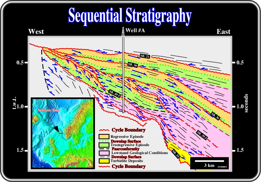
Fig. 34- In this sequential interpretation of a seismic line from the North Sea line, the stratigraphic and paleontologic results of well #A suggest that the more likely age of the unconformities, individualizing the different seismic packages, are 21 Ma, 30 Ma, 36 Ma, 39.5 Ma, 49.5 Ma and 55 Ma (millions years ago). Subsequently, the sedimentary packages are related to eustatic cycles with time durations higher than 3-5 My. In other words, they do not correspond to sequence-cycles, but to continental encroachment subcycles within which, transgressive and regressive episodes are recognized. A major downlap surface separates the transgressive interval (at the bottom) from the regressive interval (at the top). However such episodes do not correspond to systems tracts. The purple intervals represent sedimentary packages deposited during lowstand geological conditions, that is to say, periods of time during which the sea level was below the shelf break.

Fig. 35- Seismic lines, as illustrated by the markers picked in this tentative interpretation, have confused a lot of seismic interpreters, who used super and magasequences to advance lithological predictions. They erroneously considered super and megasequences as big sequences. They assumed the presence of super and mega-turbidite intervals, as it is the case in a sequence-cycle. The basic Vail depositional model, that is to say, the building blocks of sequential stratigraphy is the stratigraphic sequence-cycle deposited, as said previously, in association with a 3rd order eustatic cycle. Such a stratigraphic cycle being composed by depositional systems tracts allows lithological prediction, since each deposition system is characterized by a lithology and an associated typical fauna (facies in the Gressly's sense). Indeed, lithological predictions can be only advanced when seismic interpretation is performed at high hierarchical level. Stratigraphic cycles associated with 2cnd and 1st order eustatic cycles, as illustrated in the proposed tentative solution, are composed by of an aggradational (global sea level rising) and a progradational interval (global sea level falling), in which several high hierarchical stratigraphic intervals (sequence-cycles) can be recognized.
Sequence-cycles (fig. 36 and 37), i.e., the stratigraphic cycles deposited during a third order eustatic cycle (time duration ranging from 0.5 My to 3-5 My), are considered as the building blocks of the sequential stratigraphy. When complete, they are composed of three systems tracts (lateral linkage of coeval depositional systems). Indeed, from top to bottom, within a sequence-cycle, quite often, one can distinguish:
- Highstand Systems Tract (HST),
- Transgressive Systems Tract (TST),
- Lowstand Systems Tract (LST).
The highstand systems tract (HST) has a progradational geometry (forestepping). The upper limit is always a sequence cycle boundary. The lower limit is often the maximum flooding surface of the underlying transgressive systems tract, but, in certain cases, it can be also a sequence cycle boundary. The log pattern is typical of a coarsening and thickening upward interval (fig. 36).

Fig. 36- This figure summarizes the basic principles of Vail's sequence stratigraphy when performed at the hierarchic level of sequence- cycles. Indeed, the stratigraphic cycles, deposited during 3rd order eustatic cycles that have a time duration ranging between 0.5 and 3-5 Ma, are bounded by unconformities and composed of three main depositional systems tracts. On the other hand, as depicted, depositional systems tracts are clearly related with depositional environments. In fact, landward of the shelf break, a well (A) recognizes just the transgressive and highstand systems tracts. In deep water, the lowstand systems tract (basin floor fans, slope fans and lowstand prograding wedge) is predominant, while the transgressive and highstand systems tracts are quite condensed.
The transgressive systems tract (TST) has a overall retrogradational geometry (backstepping). The lower limit of is generally a flooding surface (1st transgressive surface), but, in certain geological conditions, it can be a sequence cycle boundary. The upper limit is generally a maximum flooding surface, but a sequence cycle boundary cannot be excluded, particularly when a relative sea level fall takes place following an expected tectonic event (fig. 37).
![]()
Fig. 37- On this seismic line, the downlap surface separating the transgressive systems tract, which geometry is overall retrogradational (backstepping), from the forestepping highstand systems tract is clearly visible. Similarly, incised valleys are visible along the lowermost unconformity, which separates an old highstand systems tract from a younger transgressive systems tract. It is interesting to note the scale of this seismic line. The time thickness of the upper sequence-cycles (two incomplete sequence-cycles) is roughly 30-40 milliseconds, that is to say, around 20-30 meters. Indeed, on seismic data, usually, a sequence-cycle interpretation requires high-resolution data or quite thick depocenters in which, generally, the thickness of the stratigraphic intervals is above the seismic resolution. In particular depocenters, as illustrated in fig. 32, the rate of deposition is so high that several sequence-cycles can be deposited in time interval lower that 3-5 My. Nevertheless, one can say that on the ground a sequence-cycle interpretation is viable, but on normal seismic data, it is normally not feasible.
As illustrated in figs. 36 and fig. 37, the typical backstepping geometry of a transgressive systems tract is, in fact, apparent. It corresponds to a stacking of regressive episodes that progressively prograde less and less. In other words, at each sea level rise increment (flooding), the depositional coastal break (roughly the shoreline) is displaced further landward, creating a ravinement surface at the top of the deposited sediments. Then, as sediments are deposited, the depositional coastal break is progressively displaced seaward, without reaching the position that it had before the rise of sea level took place. A new increment of sea level rise increases the shelfal accommodation displacing again the depositional coastal break landward and creating another ravinement surface. Then, again, deposition takes place and the depositional coastal break is progressively displaced seaward, and so forth.
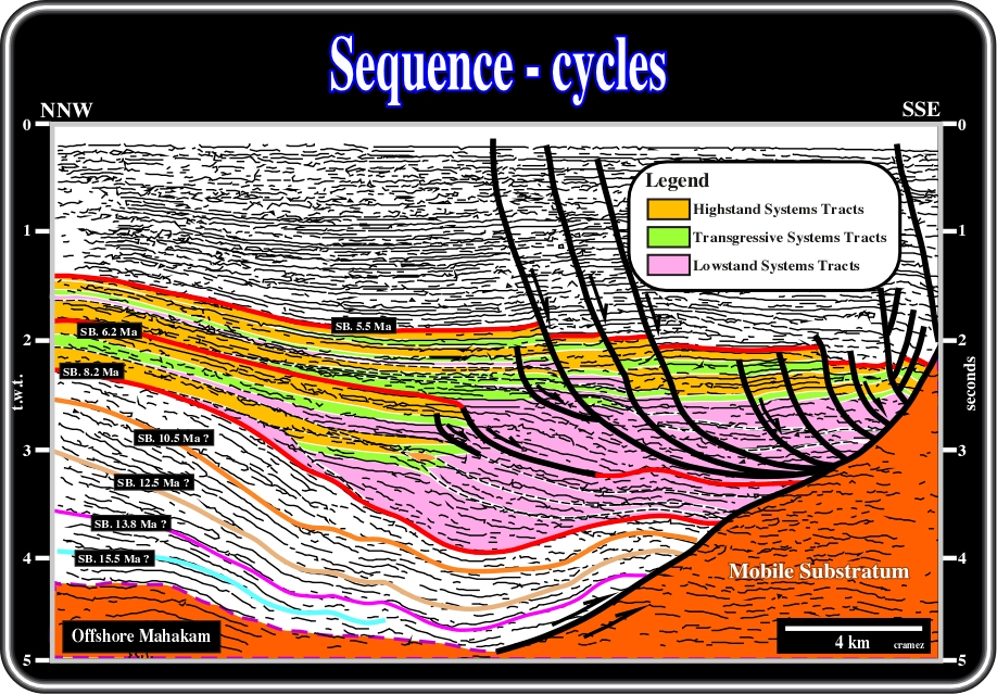
Fig. 38- On this interpretation of a seismic line from offshore Kalimantan (Indonesia), where the rate of sedimentation is quite large, the picking of boundaries of stratigraphic sequence-cycles and the depositional systems tracts for the more evident and calibrated sequence-cycles is illustrated. The majority of the picked sequence-cycles are complete, i.e., they are composed of the three depositional systems tracts: (i) highstand (HST), (ii) transgressive (TST) and (iii) Lowstand (LST). As depicted, note that between sequence boundaries 5.5 Ma and 8.2 Ma, taking into account reflections terminations, it is possible to interpret high frequency sequence-cycles. In other words, in a time interval lower than 3 My there’s more than one sequence-cycle.
The lowstand systems tract (LST) has an overall progradational geometry. From bottom to top, generally, three stratigraphic members compose a lowstand systems tract (fig. 35):
(i) Basin floor fan (BFF),
(ii) Slope fan (SF),
(iii) Lowstand prograding wedge (LPW).

Fig. 39- On this interpretation of a seismic line from offshore Namibia, a sequence-cycle is only represented by the lowstand systems tract (LST), in which the three members composing it are easily recognized not only by their stratigraphic positions but the reflections terminations as well. Indeed, just above the lower sequence-cycle boundary, characterized by an onlap seismic surface and an incised valley landward of the shelf break, the basin floor fan (BFF) is recognized by its parallel geometry. Overlying the proximal area of the basin floor fan, a slope fan (SF) with its channel-levee complexe is fossilized by a lowstand prograding wedge mainly characterized by a sharp forestepping geometry with shingled turbidites at the toe of the progradations. Submarine canyons in the upper slope enhance the upper boundary of this incomplete sequence-cycle.
Basin floor fans are located seaward of the toe of the continental slope. Slope fans are located in lower-upper slope and attached to the toe of the continental slope. Lowstand prograding wedges are located between the shelf break (lower sequence-cycle boundary) and the toe of the continental slope. Quite often, at the toe of the progradational lowstand prograding wedge (LPW), shingled turbidites are deposited. Seaward of the toe of the continental slope, lowstand prograding wedges are represented mainly by stratigraphic condensed sections (figs. 34 and 35).
A.2) Lowstand Systems Tract (LST)
In sequentialstratigraphic, turbidite deposition occurs primarily in lowstand systems tracts of stratigraphic sequence-cycles. They are mainly deposited during relative sea level falls (fig. 36). Indeed, seaward of the shelf break, the space available for sediment (water depth) is so big that it is insensitive to sea level changes. As the understanding of Vail's turbidite model relies on the comprehension of the lowstand systems tract, a quick overview is given.
As said previously and illustrated in figs. 39 and 40, a lowstand systems tract is composed of three members in which turbidte deposites are paramount: (i) Basin Floor Fan (BFF), (ii) Slope Fan (SF) and Lowstand Prograding Wedge (LPW). Note that all these turbidites are lowstand deposits, that is to say, they were deposited with a sea level below the shelf break, what exclude all turbidite deposited during highstand geological conditions as presupposed in certain turbidite Mutti's systems (fig. 21).
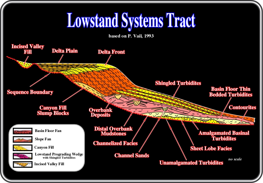
Fig. 40- As illustrated on this sketch, several types of turbiditic deposits mmay occur within lowstand systems tracts (LST). In the lower member, i.e., in a basin floor fan (BBF), the following turbidite depositional systems can be found: (i) Amalgamated basinal turbidites, (ii) Unamalgamated turbidites, (iii) Sheet lobe facies, (iv) Channelized facies, (v) Basin floor thin bedded turbidites and (vi) Contourites. In a slope fan (SF), one can find: (i) Overbank deposits, (ii) Distal overbank mudstones and (iii) Channel sands with associated (iv) Canyon fills and slump blocks. In the lowstand prograding wedge (LPW), shingled turbidites are often found at the toe of the slope progradations.
- Basin floor fans (BFF), or lowstand basin floor fans, as Vail later called them (to refute Mutti's objections), are associated with the time of rapid eustatic fall, that is to say, when sea level falls below the shelf break and sediments are transported across the shelf in incised valleys and rapidly dumped into the basin (see fig. 36).
- Lowstand fan sand lobes may develop as relatively isolated lobes or as huge accumulations of virtually basinwide extend. On the other hand, they can be attached to the other members of the lowstand systems tract (fig. 41), or completely disconnected as illustrated in fig. 42.
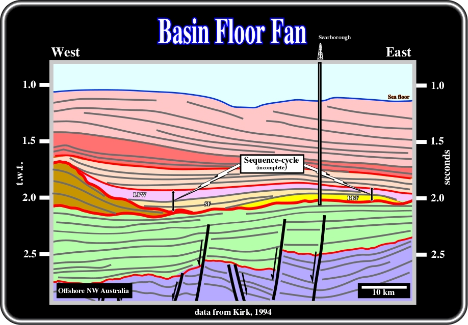
Fig. 41- On this interpretation, above a sequence-cycle lower boundary, a lowstand basin floor fan (BFF) is fossilized by the associated slope fan (SF) and the lowstand prograding wedge (LPW). In this particular example, as the lowstand floor fan (BFF) is covered by the distal shaleprone part of the slope fan (SF) and lowstand prograding wedge (LPW) , it forms a robust morphological trap for hydrocarbons. Indeed, this morphological traps was tested and a significant amount of hydrocarbons was discovered (6-12 TCF).

Fig. 42- On this interpretation, a basin floor fan interval is fossilized by a progradational interval. Assuming that the progradational interval corresponds to a highstand forestepping of a continental slope (HST), and that the basin floor fan (BFF) was deposited during lowstand geological conditions, the lowstand basin floor fan must be completely detached from the others members of the lowstand systems tract (LST). The associated lowstand slope fan (SF) and the lowstand prograding wedge (LPW) must be recognized on more proximal seismic lines (westward). If such a conjecture is refuted, new tentative solutions must be advanced: (i) the progradional interval is a lowstand prograding wedge (LPW) and the basin floor fan corresponds rather to a stack of shingled turbidites, or (ii) the basin floor fan is a highstand basin floor and therefore better explained by one of Mutti's systems.
- Reservoir characteristics of these lowstand lobes depend largely on the matrix porosity and permeability of the sands and their continuity (fig. 42). Internally, each lobe seems to have good continuity and relatively uniform matrix characteristics, except near the lateral and downdip edges of the deposit where sediments become finer grained. However, some deposits are composed of multiple lobes, in some cases derived from different shelf edge sources, which are separated from one another by very continuous pelagic and hemipelagic shales.
- Flow barriers can be expected in such deposits and it becomes important for reservoir development that the individual lobes be carefully described by interpretation of a combination of well and seismic data. Indeed, very often, the initially recoverable reserves attributed to basin floor fan reservois decrease strongly after development wells show the presence of pelagic sealing intervals between the different lobes composing the reservoir interval (see fig. 46).
- Most very large sand-lobe turbidites that form major oil and gas fields are lowstand fan systems tract sand deposits: Scarborough (fig. 42), Frigg (figs. 43, 44 and 45), Halibut, Balder, Marlin (fig. 42), Albacora, Girassol, Plutão, Kuito, etc.. Over twenty billion oil and oil-equivalent barrels have been identified in place in these fields.
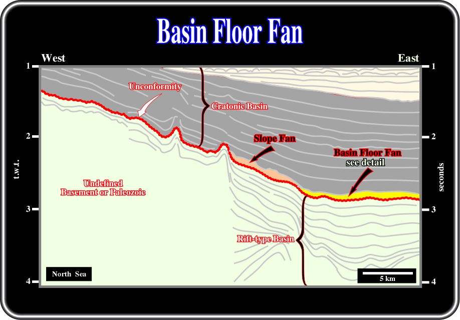
Fig. 43- On this interpretation of a regional seismic line from the North Sea, a major tectonically enhanced unconformity separates the rift-type basin from the cratonic basin. The geometry of this unconformity gives roughly the morphology of the base of the cratonic basin. Therefore, the limit between the abyssal plain and the lower slope can be recognized on the right part of the line, by the change in dip of the unconformity. In addition, a basin floor fan (BFF) is distinguished at the toe of the continental slope on the abyssal plain, and a slope fan (SF) at the base of continental slope. The geometric relationships between these fans are better depicted on the close-up shown in fig. 44.

Fig. 44- This interpretation (detail of fig. 43) shows the relationships between the distal part of the slope fan (SF) and the basin floor fan (BBF), which is not completely detached, since its landward edge is fossilized by the seaward overbank deposits of the slope fan. Note that undulated morphology of the basin floor fan is not real. It is induced by lateral velocity changes and strongly enhanced by the vertical exaggeration. On the other hand, on this particular example, the basin floor fan is reflection free.
- Basin floor fans can be, under certain conditions, partially eroded by seafloor currents and the liberated sediments redeposited as contourites as illutrated in figs. 40 and 45.

Fig. 45 - On this close-up of an interpretation of a seismic line from the North Sea, above a sequence-cycle boundary (unconformity or basinward correlative surface), a basin floor fan (BFF) is located. After being deposited, it was partially eroded and the liberated sediments were deposited not to far as contourites. The reflections within the basin floor fan are more or less subhorizontal, while those within the contourites are clearly dipping eastward. Notice that the reflector induced by the water-oil plane contact is roughly parallel to the bedding of the basin floor fan.
- On electrical logs (SP, Gamma ray, Resistivity, Sonic, etc.), basin floor fans exhibit a typical cylindrical pattern as illustrated in fig. 46.
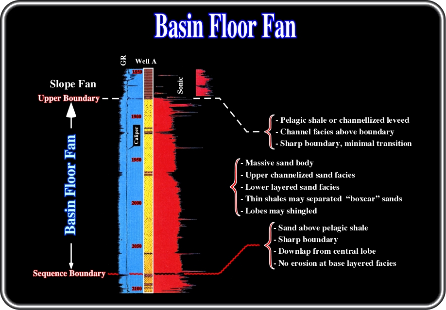
Fig. 46- On this electrical logs (North Sea well), a basin floor fans (BFF) exhibits characteristic patterns with sharp boundaries and thin shale horizons separating massif boxcar sand lobes. The lower limit corresponds to a sequence boundary, while the upper limit corresponds, quite often, to a sharp transition to channel levee complexes of slope fans, when it is attached to the other lowstand systems member.
- Seismic stratigraphic analysis, using eustatic sequence concepts is the best method of searching for reservoirs and particularly to those associated with basin floor fans. As petroleum exploration moves into deep marine waters, these deposits are among the most promising targets. The exploration applications of the lowstand basin floor fans can be summarized as follows:
(a) Reservoir
- Typically excellent k & ø.
- Continuity variable, often a problem in upper channelized lobes.(b) Migration
- Vertical from deeper sources.
- Possible downward and lateral from condensed section shales(c) SOURCE
- Leakage from deeper beds.
- Possible top and condensed section shales.(d) TRAPS
- Typicallynon structural. Morphological traps.
(e) SEAL
- Excellent, pelagic shale of condensed section.
- Risk of no seal if overlain by slope fan.to continue press
next
![]()