
Universidade Fernando Pessoa
Porto, Portugal
Depending on the geometry of the fault plane, volume problems created by extension can be solved for normal faulting in two different ways, as illustrated in fig. 119 and fig. 120.
On this model (fig. 119), the geometry of the fault plane creates a potential void when the hangingwall is displaced forward. Subsequently the sediments are lenghtened to fill the space created. However, the lenghtening mecanism depents on the rheology of the sediments, in other words the accommodation depends is the sediments are brittle or ductile, as illustrated below.
Fig. 119- When the geometry of the fault plane is curved, to avoid a potential void, the sediments are lengthened by antithetic normal faults dying in a major synthetic curve fault limiting the hanging wall in downdip direction (brittle material). When sediments are ductile, faulting is quite limited and, in certain cases, completely absent: a rollover in the hangingwall solves the volume problem.
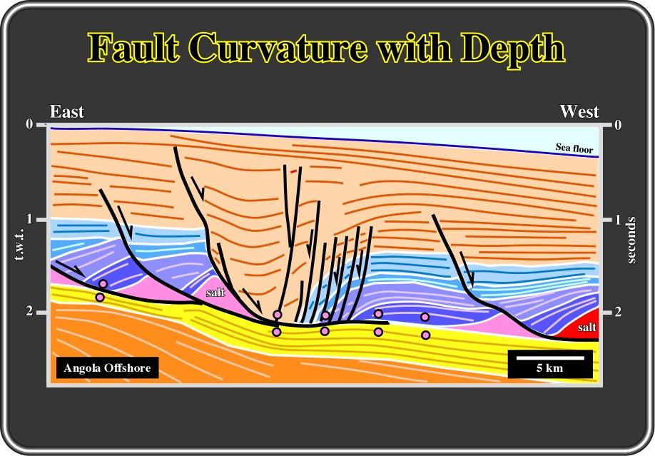
Fig. 120- The major curvilinear faults limiting the Tertiary depocenter recognized on the middle of this interpretation of a seismic line, from the Angola offshore, illustrates the lengthening and volume accommodation (filling potential voids) in a brittle sedimentary interval. Several antithetic faults help to accommodate the sediments of downthrown-faulted blocks. The intervals coloured in blue are mainly carbonates. In fact, their facies (lithology) and their brittle rheology can be partially deducted from the geometrical of the major synthetic fault (westward vergence). The dip of the fault planes change with depth. It becomes steeper in the less compactable intervals (see later).

Fig. 121- The major growth fault, to the left of the line interpretation, illustrates a ductile deformation and potential void accommodation. The sedimentary thickening toward the fault plane is easily recognized. Near the apex of the antiform, the lengthening of the sediments requires not only synthetic faults but antithetic ones as well. Such deformation suggests a more brittle deformation, which can be explained by a higher compaction of the sediments.
In this model, the geometry of the fault plane is such that when the hanging wall is displaced to allow lengthening, there is (theoretically) an overlap between both faulted-blocks, which can be solved in two different ways illustrated below.
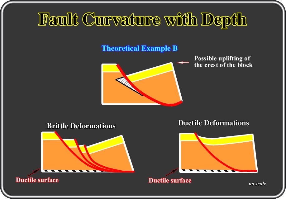
Fig.122- In this geologic model, the volume problems of curvilinear faults (in surface and in depth) is solved either by synthetic listric faults: (i) several drag-faulted blocks (riders), when sediments are brittle or (ii) by a synform, when sediments are ductile.

Fig.123- The lengthening of the infrastructure of the back-arc basin in Asia is often accomplished by several curvilinear normal faults dying in the same detachment surface. As will be shown latter, there is a relationship between the rotation of the faulted-blocks (mainly the downthrown sides) and the depth of the detachment, i.e. when the fault plane becomes sub-horizontal.
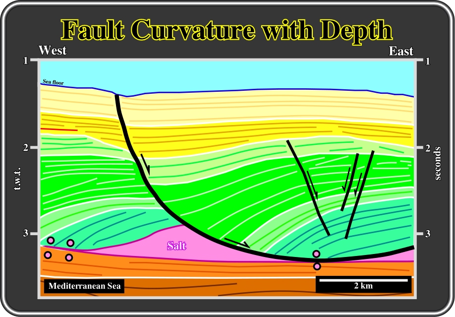
Fig. 124- The extension and thickening of post-evaporite sediments in the Mediterranean Sea is often used to illustrate a ductile deformation along a curvilinear normal fault. Notice that we use a rather curvilinear normal fault instead of a listric fault. We will restrict listric faults to the curvilinear normal faults exhibiting in a profile a normal geometry updip and a reverse geometry downdip and seaward. Etymologically, listric comes from Greek listron, which means shovel or spoon.
c.5- Normal Faulting & Block Rotation
As said previously, normal faults can be grouped in two major families:
a) Faults with rotation of the fault-blocks (Fig. 125), which can be
a.1- Planar faults
a.2- Curvilinear faultsb) Faults without rotation of the fault-blocks (Fig. 126).
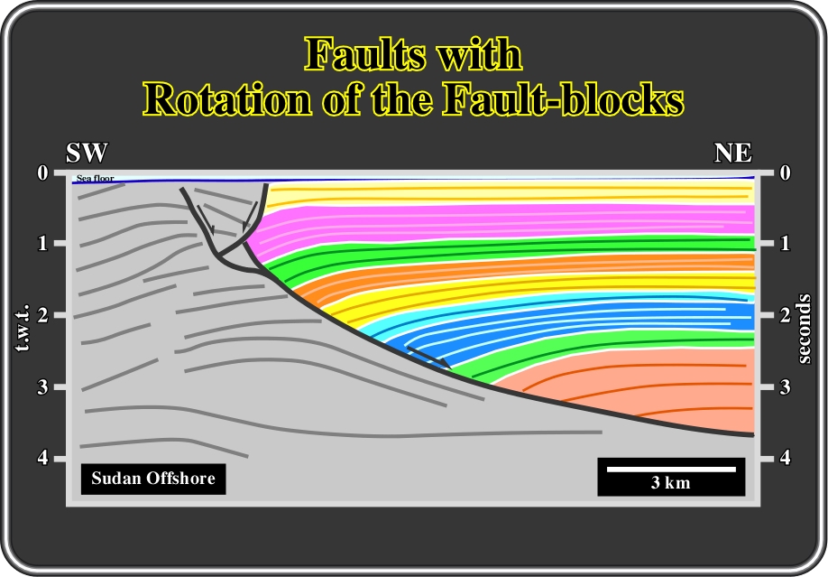
Fig. 125- This close-up interpretation of a seismic line from offshore Sudan, illustrates a normal fault with a significant rotation of the hangingwall. The fault movement is, for the majority of the intervals of the downthrown block, synchronous with the sedimentation, since some intervals thicken slightly toward the fault plane.
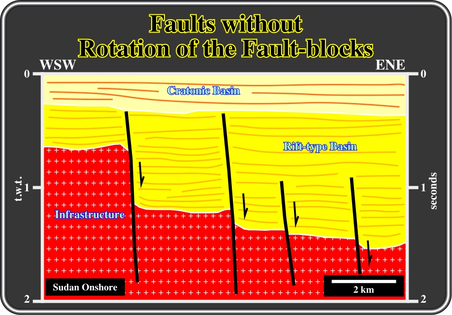
Fig. 126- This geological interpretation of a seismic line from the onshore Sudan, illustrates normal faults without rotation of the fault blocks. However, it must be noticed that the seismic line is vertically exaggerated. In other words, a natural scale the dip of the faults is not so high. On the other hand, it is quite evident (volume problem) that in depth some flattening of the faults planes must exist. In addition to the poor quality of the seismic lines no wells penetrate deep enough to test such a hypothesis.
c.5.a- Faults with Rotation of the Fault-blocks
Faults with rotation of the fault-blocks, as depicted in the sketch illustrated in fig. 127, can be:
(i) Planar and
(ii) Curvilinear
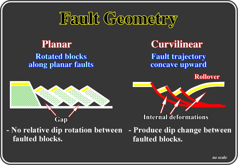
Fig. 127- As said previously, and illustrated below, when the lengthening of sediments is made by rotation of the faulted-blocks, two different mechanisms can be involved, depending on whether the fault planes are planar or curvilinear: (i) lateral flowage (dominos) or (ii) internal deformation (curvilinear and listric faults).

Fig. 128- In this tentative solution of the interpretation of a seismic line from onshore Yemen, extension is made by rotation of the faulted-blocks along planar faults. Admittedly, this kind of lengthening requires some mechanism to fill the space created at the bottom of each fault plane, particularly when the infrastructure is not involved in deformation. In this particular example, it is possible that some material from the infrastructure (likely salt) flowed upward to fill the space created, (see next figure).
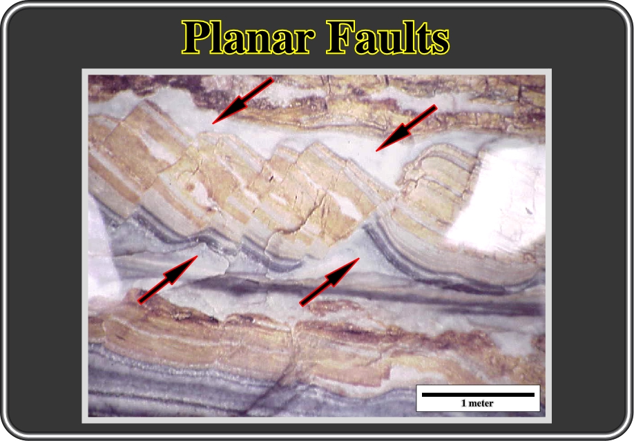
Fig. 129- Dominos, that is to say, rotated fault-blocks along planar faults, are well illustrated in this photograph. It can be is easily recognized that volume problems at the top and bottom of each fault were solved by flowage of more ductile sedimentary horizons toward potential void areas, as indicated by the arrows.
Different geometrical models have been proposed to calculate the amount of extension, whether in planar or curvilinear faults.
Here extension takes place by gliding of both fault-blocks along a planar fault. The amount of extension can be calculated by knowing the geometries of the fault plane and faulted blocks, as illustrated in the next figures.
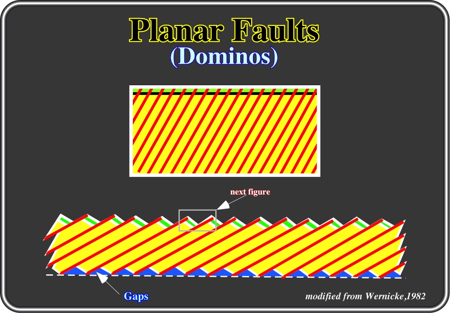
Fig.130- In this geologic model, sediments uniformly deposited (top) were later lengthened by planar and rectilinear faults (domino faults). Such an extensional mechanism creates a potential void at the toe of each fault plane. However, as seen previously, potential voids, or gaps, must be filled. Nature has aversion to voids. The amount of extension created by such a mechanism can easily be calculated as shown in fig. 131.
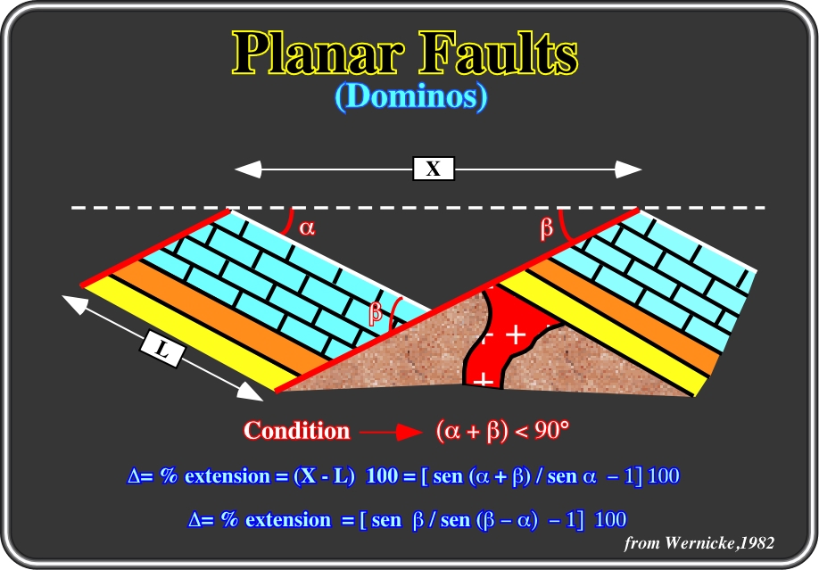
Fig. 131- Knowing the dip of the fault plane and the dip of the beds, which is the same in both faulted blocks, the percentage of extension can easily be calculated, as depicted above. Wernicke and Burchfield (1982), proposed a cross-plot which gives the percentage of extension without making any calculation (see next figure).
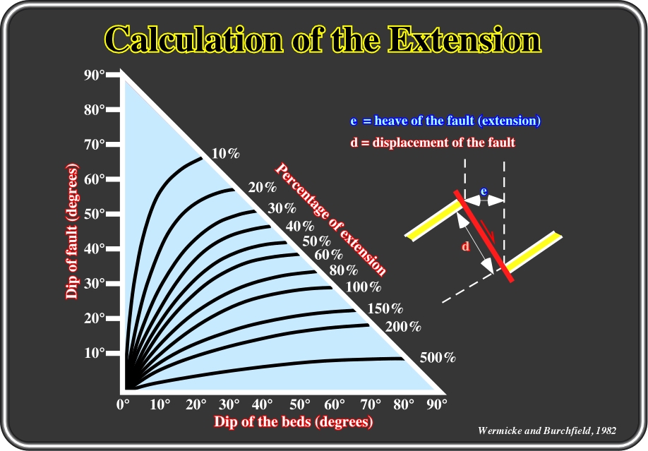
Fig.132- In planar faults, which exist only in the upper levels of the Earth’s surface (sediments compact with depth), the percentage of extension can be calculated using this diagram where (i) the dip of the fault, (ii) the dip of the beds and (iii) the percentage of extension are related.
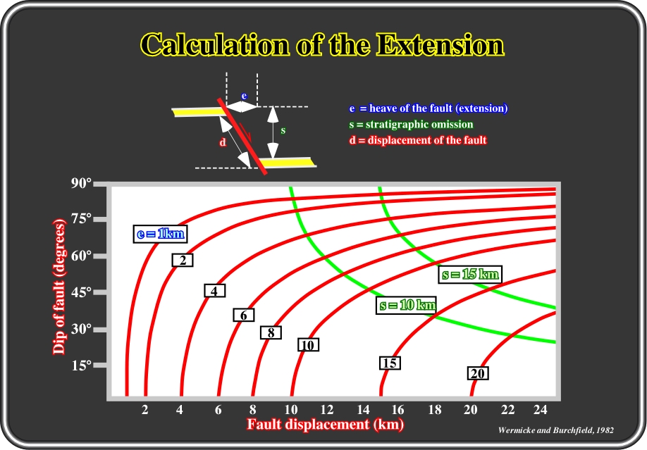
Fig.133- The amount of extension can also be calculated using the relationship between the dip of fault and fault displacement. The amount of missing stratigraphy (s, in the sketch) can also be calculated.
c.5.b (ii)- Curvilinear Faults
In these faults, extension takes place by displacement of the fault-blocks along a curvilinear fault. The dip of the beds located in the downthrown fault-block is higher than the dip of the beds in the upthrown. Generally, one or several downthrown fault-blocks are created downdip with an increment of the dip of sedimentary beds.

Fig. 134- Very often, on the seismic lines of the Gulf of Mexico, one can see nice curvilinear normal faults as illustrated in the above interpretation. Roughly, they follow Hamblin’s model (1965). The gliding of the downthrown faulted-block is synsedimentary, so they are growth faults, i.e. the sedimentary intervals thicken progressively toward the fault plane. The volume created by lengthening is filled by the rollover deformation of the sediments, in which the angle between the beds and the fault plane must be constant, which allows the calculation of the amount of extension.
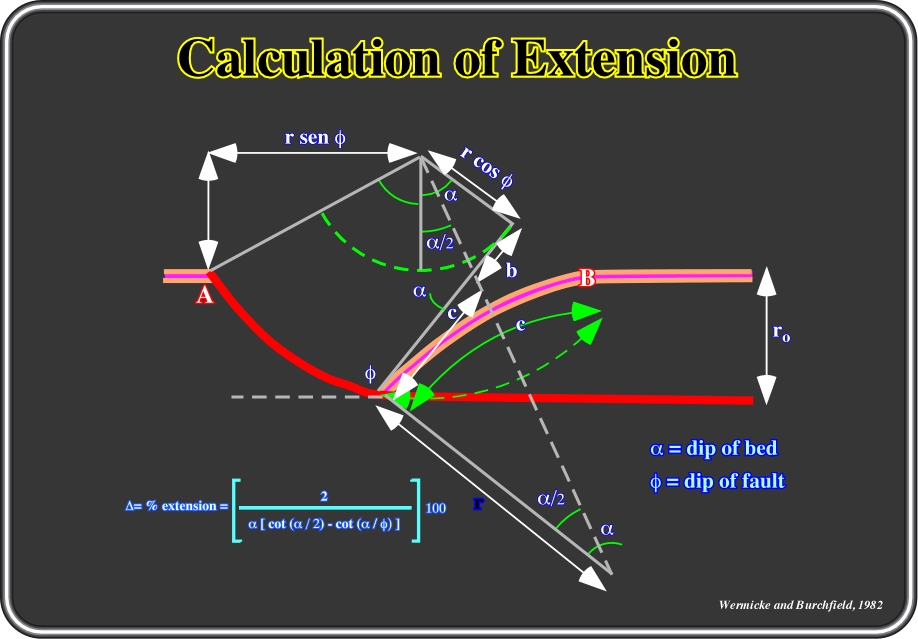
Fig. 135- Theoretically, in a curvilinear fault, the angle between the beds and the fault plane must be constant during deformation and the curvilinear segments of the fault plane are circle arcs. The percentage of extension can be calculated knowing the distance AB, the dip of the beds and the dip of the fault (measured perpendicular to the rollover). Cross-plots are available to determine the percentage of extension in a curvilinear fault (fig. 136).
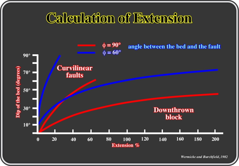
Fig.136- Diagram proposed by Wernicke and Burchfield to determine the percentage of extension in a curvilinear fault, when the angle between the bed and the fault plane ranges between 60° and 90°.
A- Imbricated Curvilinear Faults
Imbricated curvilinear normal faults are those that die in a common détachment plane and are not spaced very far apart. Indeed, one can say, roughly, that they are normal curvilinear converging faults, as illustrated in fig. 137.
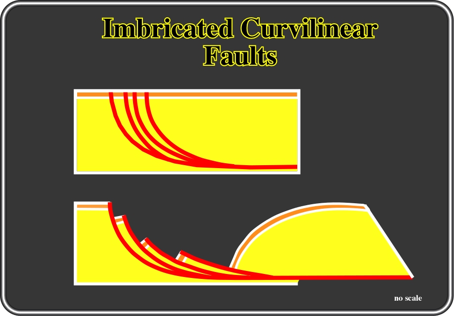
Fig. 137- Shingled normal curvilinear are found in the field, when the curvature (geological map, for instance) of the fault plane is quite sharp (fault planes flatten in a relative high level ) and extension is not big enough to detach the faulted-blocks (as a raft), which's implies the creation of several converging downward faults.
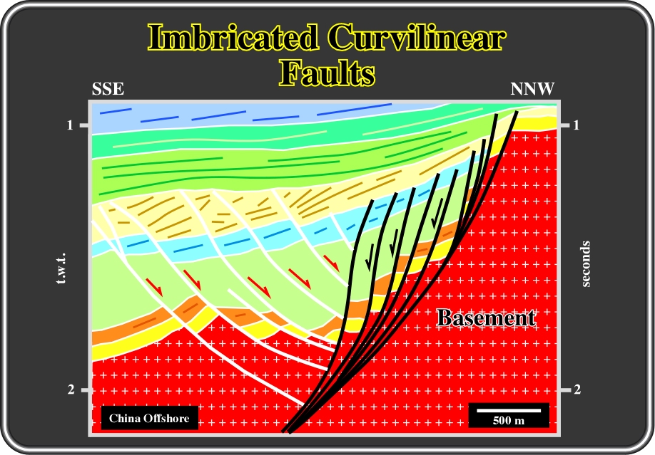
Fig. 138- The antithetic normal curvilinear faults (coloured in white) can be considered as imbricated along the last southward synthetic fault (coloured in black). The depth of flattening of the fault planes is a consequence of the extension and the geometry of the faults planes, as indicated by the antithetic faults. Indeed, when the curvature of the faults is small, the depth of the detachment plane is quite important and so the rotation of the beds is relatively small.
press
![]()
Send E-mail to ccramez@compuserve.com or cramez@ufp.pt with questions or comments about this short-course.
Copyright © 2000 CCramez
Last modification:
Agosto 27, 2006
