Universidade Fernando Pessoa
Porto, Portugal
I- Ground Rules (cont.)
e) Folding and Fracturing
Tentative interpretations (cross sections or geological interpretations of seismic lines) should be mechanically sound and conform to the elementary principles of folding before fracturing. The next examples point out some of the key principles that a geologist should know before starting to interpret geological data.
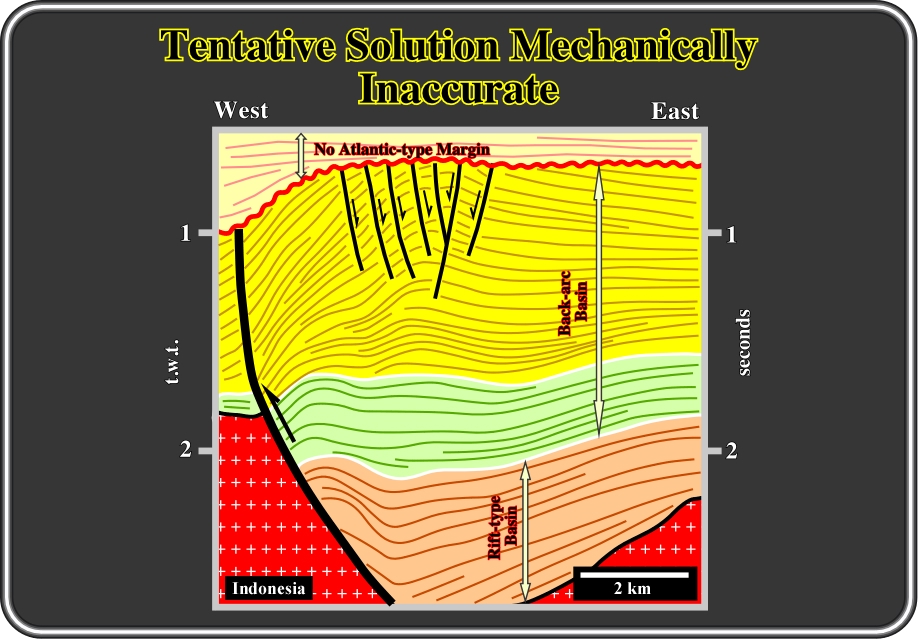
Fig. 19- This geological interpretation of a seismic line from offshore Natuna (Indonesia) looks plausible. However, it can be easily refuted. The elementary principles of folding and fracturing are not respected. The interpreter proposed normal faulting coeval with shortening near the apex of the anticline, which was created by tectonic inversion (reactivation of pre-existent normal faults and buckling), that is to say, the age of faulting is supposed to be contemporaneous with the structure. Such interpretation does not mechanically conform to the following basic geologic concept (strain partitioning): “Sediments cannot be shortened and lengthened at same time, in the same place”. In fact, during a compressional tectonic regime characterized by
1 horizontal and
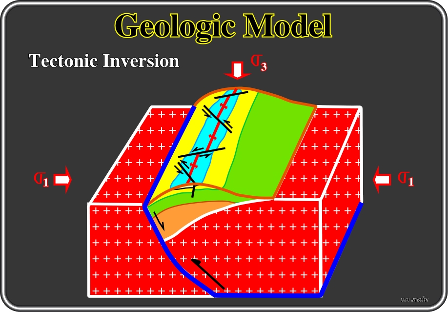
Fig. 20- Small strike-slip faults (tear-like faults), located near the apex of anticlines, were studied and described by C. E. Wegmann (1956), in the Jura Mountains. He wrote: "The strike of beds and the strike of the bent axes of the different anticline compartments do not correspond to the strike of the macro anticline itself. The local axes are rotated. This rotation corresponds to a longitudinal lengthening typical of a lot of folds. The beds when bent developed slickensides on the bedding surfaces, they are not in planes perpendicular to the tectonic stress. This means, that the symmetric planes suggested by quick interpretation do not correspond to realistic interpretations. The geometry of the different structural elements of some anticlines gives a triclinic polar symmetry”. “Similar strike-slip faults are always found on anticline structures created in association with tectonic inversion". Field studies and seiscrop interpretations corroborate not only the presence of these faults on the apexes of anticlines but their conjugate geometry as well (see Fig. 21).
Jura folds have been considered as prototype folds. Two different mechanisms have been proposed to explain their origin and several hypotheses have been invoked to solve the associated volume problems, particularly in the core of the structures. The two mechanisms are:
(i) Uplift and
(i) Lateral Shortening.
Nowadays, the lateral shortening hypothesis, in which the folds are created by a shortening induced by horizontal tectonic stress, is followed by the large majority of geologists. However, two variants are possible:
(ia) Passive Basement (stresses conveyed by the sedimentary cover) and
(ib) Active basement (stresses conveyed by the basement).
The volume problems created by folding in the core of the anticlines have been solved indifferent ways:
(A) Folding of the basement;
(B) Thrusts of basement;
(C) Crushing of basement;
(D) Flowing of mobile layers;
(E) Disharmonic folding in the heart of the anticlines.
Petroleum field geologists who have worked in onshore Iran know well the small compressional strike slip faults than Wegmann described in the Swiss Jura Mountains. Indeed, in all geological maps (surface or sub-surface), they are clearly recognized and mapped near the top of anticline structures (figs. 21 and 23). However, generally, they are small enough to be under seismic resolution as illustrated in figures 22 and 24.
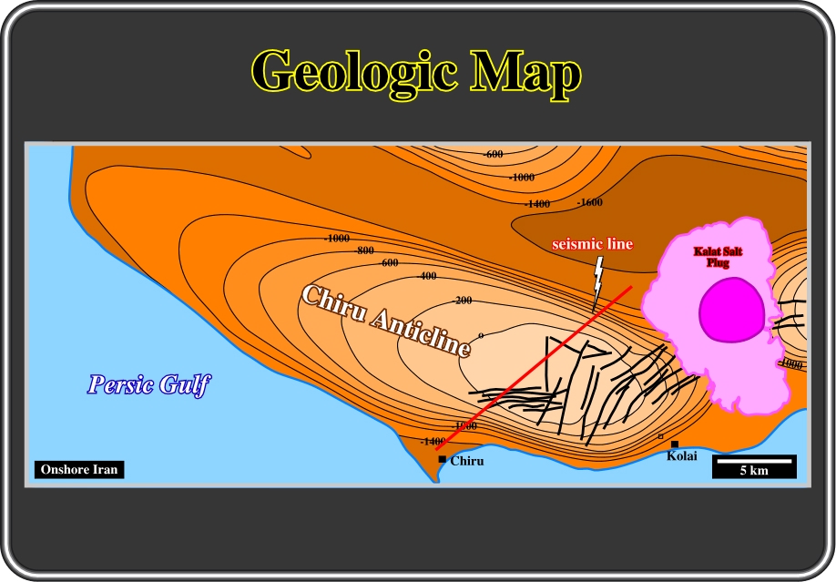
Fig. 21- The Chiru anticline is illustrated by a composite map built with surface and seismic data. Small compressional strike-slip faults are recognized near the top of the anticline. They elongated the anticline along its axis, i.e. along the middle effective stress (
Notice that “extrados fractures” are only developed within a sedimentary bed, above (extensional) and below (compressional) the neutral surface. Indeed, as pointed out by Price (1990), in tangential longitudinal strain folds, the maximum strain occurs at the hinge and no strain occurs at the inflexion point. As its name implies, in this type of folding, one of the principal strains is always parallel (tangential) to the boundary layer. The outer arc of the hinge area (extrados) experiences an extension and the maximum principal extension is parallel to the boundary layer. Conversely, the inner arc (intrados) is compressed and the minimum principal extension is parallel to the boundary layer. A line along which there is no strain separates these two states of strain. This surface is called the neutral surface. It separates an area of layer-parallel compression from one of layer-parallel extension.
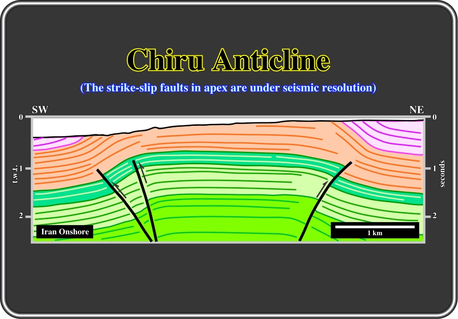
Fig. 22- Here, the Chiru anticline is illustrated by the interpretation of a strike seismic line, that is to say, a seismic line shot parallel to the maximum effective stress (
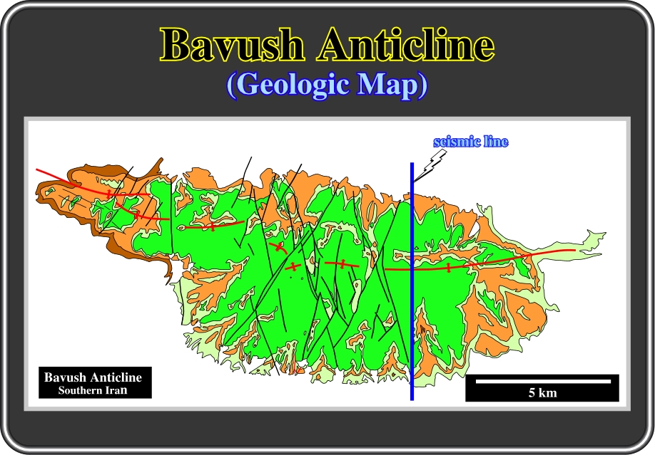
Fig. 23- This geological map of the Bavush anticline illustrates quite well the compressional strike slip faults that elongate the anticline structure along its axis, i.e.,
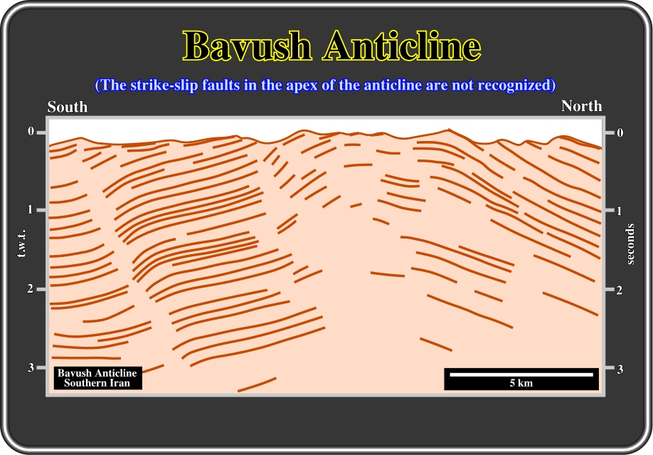
Fig. 24 - On the seismic line perpendicular to the axis of Bavush anticline, which location is shown in Fig. 23, we just noted the key chronostratigraphic reflectors. Such an effortless interpretation strongly corroborates the compressional tectonic regime recognized in the field. Indeed, using just the geometry of the seismic markers, one can say the sediments were shortened and uplifted by folding and reverse faulting. However, as depicted, and as said previously, there are no seismic reflectors associated with the fault planes of the reverse faults. The fault planes are just materialized by the discontinuity of the seismic horizons. Nevertheless, when a fault zone is filled by salt, volcanics or other highly acoustical impedance material, it can be denoted by seismic reflectors. These quite significant reverse faults are not shown on the geological map illustrated in fig. 23. They outcrop outside of the mapped area (apex area). The obvious strike slip faults on the geological map (Fig. 23), near the apex of the structure, are not visible on the seismic data because they are under seismic resolution. It is interesting to point out here that this line corroborates the hypothesis assumed previously that, in general, there are no seismic reflectors associated with faulting.
f) Facies
The lithology (facies) of the rocks involved give us a certain clue to the original attitude of the beds. Whereas a large amount of sedimentary rocks are deposited in near horizontal attitude, we should be aware of the exceptions and take them into account when structural deformation is restored.
In fact, on seismic lines, which geological interpretations are illustrated from below, it is quite evident that the sediments deposited on the continental slope, for instance, show a basinward pristine sedimentary dip. Such geometry is not associated with any tectonic tilt or deformation. No sedimentary material was removed by erosion. So, in spite of the fact the volume of the sediments is preserved during deformation, it changes laterally. Indeed, from the beginning, the sedimentary packages taper at both ends (continent and seaward). Summing up, in slope environments (alluvial, deltaic or continental), Goguel's law is respected, but it is difficult to use to test tentative interpretations, since the volume of sedimentary intervals change laterally.
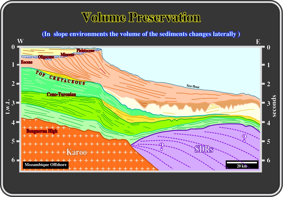
Fig. 25- In geological settings where continental slope environments are dominant, Goguel’s law is difficult to use to test proposed tentative interpretations. Indeed, as depicted by the geometry of the illustrated seismic reflectors, the majority of sediments were not deposited horizontal horizontally. They have progradational geometry. The systems tracts, which compose the different chronostratigraphic cycles, taper on both ends in different depositional systems. In other words, the sedimentary packages after reaching a maximum of thickness, become, progressively, condensed seaward. In deep water, significant erosion may have taken place in association with deep-water currents as suggested by the geometric relationships (toplap and onlap) linked with the Tertiary deep submarine valleys. The reader should not forget the proposed interpretation is in time (t.w.t.). The pitfalls created, in depth, by the uppermost shelf break must be taken into account.
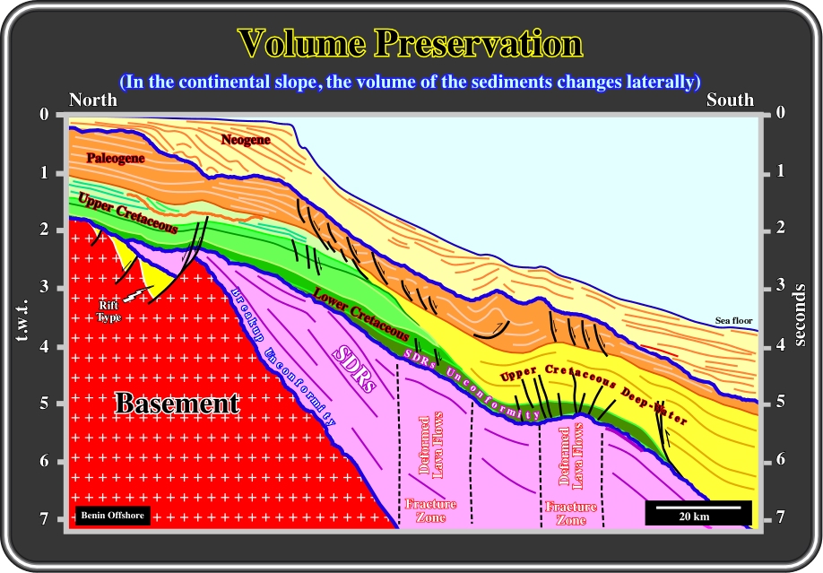
Fig. 26- In this tentative interpretation of a regional seismic line from offshore Benin, the limit between the shelf and slope sediments is easily recognized, particularly in the Neogene. Seaward of the successive Neogene shelf breaks, the volume of sediments changes laterally. Indeed, it is easy to see the fusiform geometry of slope strata and the aggradational-mounded geometry of the turbidite submarine fans (probably slope fans). The geometry of the slope sediments strongly contrasts with the more or less constant thickness and parallel internal configuration of Paleogene and Upper Cretaceous platform sediments. On this interpretation, it is interesting to point out the profusion of subaerial lava flows (SDRs) and the presence of two major fracture zones. The reactivation of these fracture zones seems to have locally shortened the sedimentary cover. These types of lava flows fossilize rift-type basins and hence underline the break-up unconformity. Summing up: Seaward of the shelf break, that is to say, in deepwater environments, the coherency of tentative interpretations cannot be estimated by Goguel's law. The volume of lateral sediment changes and the volume of removed deepwater sediments (by deepwater currents) can be quite significant.
Due to differential subsidence (rift-type basins) and compensatory sedimentation (induced by a mobile substratum), areas where subsidence is greater will usually receive more sediments than areas of lesser subsidence. In basins with large lateral changes in subsidence the concept of volume preservation is difficult to use to test tentative interpretations, as illustrated next.
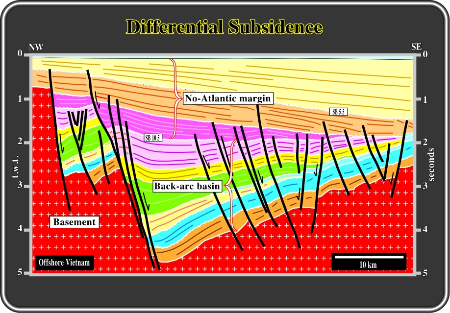
Fig. 27- On this interpretation, the differential subsidence of the back-arc basin (Offshore Vietnam) creates significant lateral variations in the thickness of sedimentary packages. The majority of sedimentary intervals, forming the back-arc basin, thickens toward the major faulted zone bordering the half-graben. Contrariwise, the sediments of the no Atlantic-type divergent margin (marginal sea) thicken seaward (note the purple interval postdating SB 10.5 Ma). Therefore, in such conditions, the volume preservation concept, proposed by Goguel, cannot be applied. In this particular example, it is interesting to point out that not all sedimentary packages within the back-arc basin exhibit divergent internal configuration. In fact, the two lower intervals (brown and blue) have a constant thickness and an internal parallel configuration. Such geometry suggests that organic rich lacustrine shales are likely (potential source-rocks), while the continentward divergent internal configuration (thickening toward the bordering fault) suggest a sandprone facies (potential reservoir-rocks). Indeed, as empirically revealed by Bally (1985), in a rift-type basin, when the rate of extension is balanced by the terrigeneous influx, the depositional water depth is about zero, and so, the sedimentary facies is sandprone as the thickness of the interval increases towards the fault responsible for the differential subsidence. On the contrary, when the terrigeneous influx is too small, and it does not balance the rate of extension, a water depth is created. So a lake, such as Lake Tanganyika, is formed in which organic matter can develop and, later, be preserved within a predominantly shaleprone and more or less isopachous sedimentary interval.
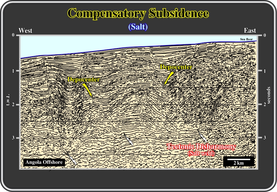
Fig. 28- In offshore Angola, salt flowage induces compensatory subsidence and thick depocenter areas that alternate with relatively thin coeval intervals. In addition "raft tectonics", when present, strongly increases the difficulty of testing geologic tentative interpretations by the rule of volume preservation. Indeed, on this interpretation, the reflector markers geometry suggests a tectonic disharmony at the level of the bottom of salt or salt weld. The underlying strata (or associated chronostratigraphic reflectors) are undeformed, while the overlying strata are strongly lengthened by halokinesis and extension. Once more, one can notice that there are not seismic reflectors associated with fault planes. Subsequently, the picking of the fault planes cannot be executed in continuity as when picking a marker, but by mapping the envelop of the discontinuities between the seismic reflectors, as illustrated previously.
One of the most important post-depositional processes that may considerably alter the architecture of a sedimentary basin is compaction. Compaction may involve either a mechanical change that closes the pore spaces in a rock or a chemical alteration of the rock. Often, sedimentary geologists restrict their definition of compaction to the physical removal of pore space, and ignore cementation. The latter process needs to be taken into account when modeling the burial history of sediments. In basins, there is usually a variation in lithology, both horizontally and vertically, reflecting changes in the depositional environment. From the basin edge to its center, the sediment type may change from well-cemented quartz-rich sandstones, grade to siltstones and eventually shales. Since each rock type has a different porosity-depth curve, the effects of compaction will vary greatly across a basin.
Summing up: The mechanism of differential compaction drastically alters the initial attitude and thickness of sediments sometimes even before any structural deformation takes place (Fig. 29). Subsequently, the use of Goguel's law to test tentative solution is not recommended in areas where differential compaction is paramount.
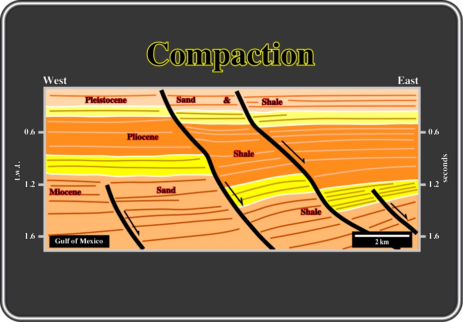
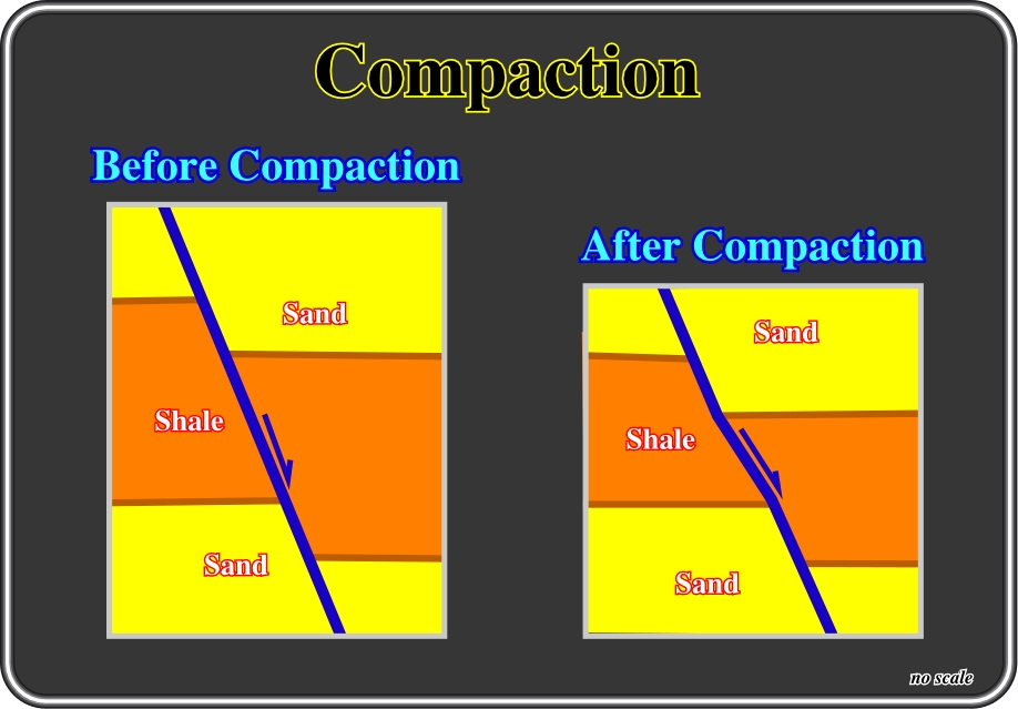
Fig. 29- This tentative interpretation of a seismic line from onshore Louisiana, illustrates the effect of compaction in the architecture of the sediments and how it affects fault plane geometry. The dips of the fault planes change according the lithology due to compaction as depicted in Fig. 30. In fact, the dip of a fault plane is higher in less compactable intervals. Therefore, the distortion of the faults planes allows interpreters to advance lithological prediction in the upthrown faulted-blocks (footwalls).
Fig. 30- The dips of post-compaction faults are higher in the less compactable sedimentary intervals. Before compaction, the dip of the fault is the same in both sand and shale intervals. After compaction, let’s say after 2.000 meters of loading, as a shale is much more compactable than a sand, the dip of the fault become smaller in the shale interval due to a more important thickness reduction. As we will see later, such a change in the geometry of the fault plane creates a volume problem in the hanging wall, where the sediments must accommodate to the new volume conditions. Indeed, it is quite evident that when the fault plane becomes less steep, there is formation of a potential void, which the sediments must fill by lengthening themselves since, as said previously, Nature has a repulsion to empty space.
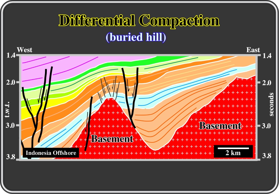
Differential compaction is often created by basement highs (buried hills) and intruded bodies (salt, shale or volcanics), which can significantly distort the geometry of sediments and particularly their thickness as illustrated below.
Fig. 31- This interpretation, of a seismic line from the eastern Sumatra offshore, illustrates the differential compaction distortion associated with a buried-hill of the basement. Above the buried-hill, the sediments are more compacted, which means that locally, they are thinner and lengthened. In other words, differential compaction creates antiform structures and not anticlines. Antiforms are extensional structures and seldom can be considered as potential four way dip traps. The sediments were lengthened by normal faults, with opposite vergence, in order to fill the void created by extension. Subsequently, the associated potential traps are morphological by juxtaposition and not structural. The juxtaposed rocks located in the other side of the faults seal the potential reservoir-rocks. On this subject, it is important to notice that, as said a long time ago by Downey 1984, 1994), a fault-trap is something like a misnomer. A fault never traps. What traps are the sediments juxtaposed to the potential reservoirs on the condition that their displacement pressure would be bigger than the displacement pressure of the potential reservoir. However, theoretically, when normal faulting allows communication between reservoirs intervals, the closed surface can be bigger and the trap can be eventually considered as four-way dip closure. Take note that in a structural trap the sealing-rock, which forms the trap since it closes the reservoir, is by definition, parallel to the reservoir-rocks.
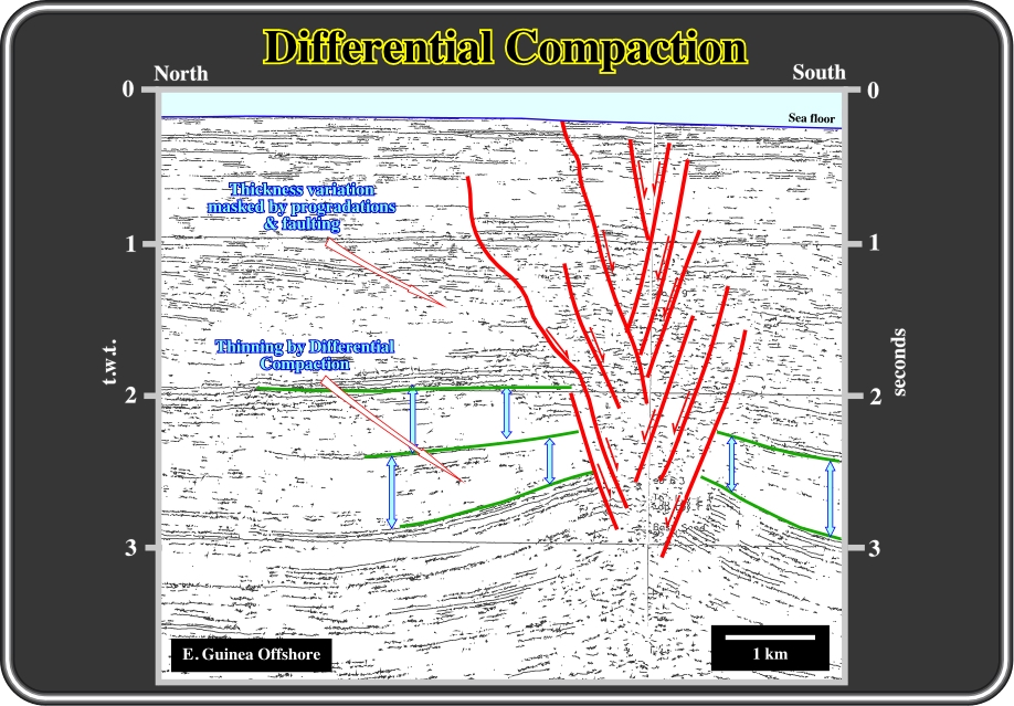
Fig. 32- We have tried several times to test this tentative interpretation but, so far, we could not refute it. The reason why we are interested in refuting this interpretation is quite simple. The structure recognized on the southern part of the line is interpreted by certain geologists as an anticline, that is to say, as a compressional structure developed at the toe of a listric (Price's sense) normal fault. So the major question, or problem that the interpreter must solve is simple and it can be formulated as follows: Are the sediments shortened or lengthened? Following the scientific methodology proposed by different philosophers of Science, the interpreter must advance at least two tentative solutions: (i) one explaining that the sediments were shortened and (ii) other explaining that the sediments were lengthened. Then, with all geological data available, he must criticize both hypotheses. Taking into account all data, a hypothesis that the sediments were shortened is easier to refute that the other one. Indeed, as on can see not only is there any evident angular unconformity between deformed and undeformed sediments but there is well-developed normal faulting on the top of the structure. In addition, two evident sedimentary packages thin toward the apex of the structure. On the contrary, differential compaction structures, for instance antiforms, can be induced by post-sedimentary volcanic intrusions. The structure illustrated here presents all characteristics of a differential compaction antiform induced by a volcanic plug, which are well known in the area. The overlying sediments are lengthened and not shortened. The thickness of the sedimentary intervals is thinner toward the top of the structure. Post-sedimentary normal faulting is well developed. The faults have opposite vergence. Between 1-2 seconds, the forestepping geometry of the sedimentary package is strongly masked by compaction effects.
Before going ahead you are going to see some typical examples, based on those proposed by Arbenz (1968) in a old short course of Shell Oil company:
Example 1)
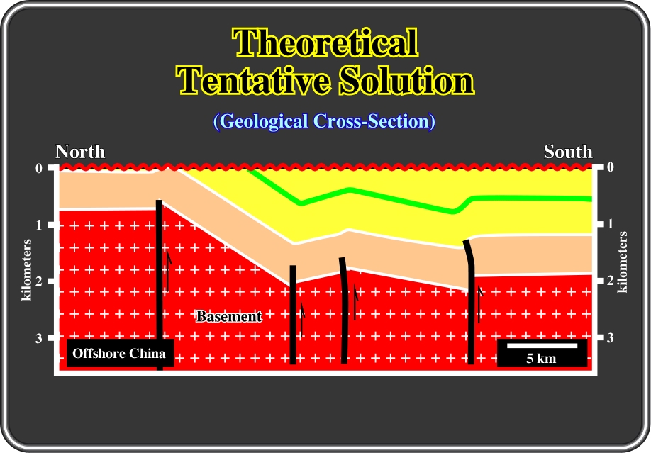
Fig. 33- In spite of the fact that vertical faults are, as said previously, likely strike-slip faults and not reverse faults as depicted (vertical exaggeration taken into account), this tentative solution for a cross section in a block faulted region (see later) does not survive to a simple geometrical critical test. Indeed, as the fault planes are drawn vertical, regardless the dip of the block surfaces, a lot of volume problems arise from such a tentative solution as illustrated in the next figure.
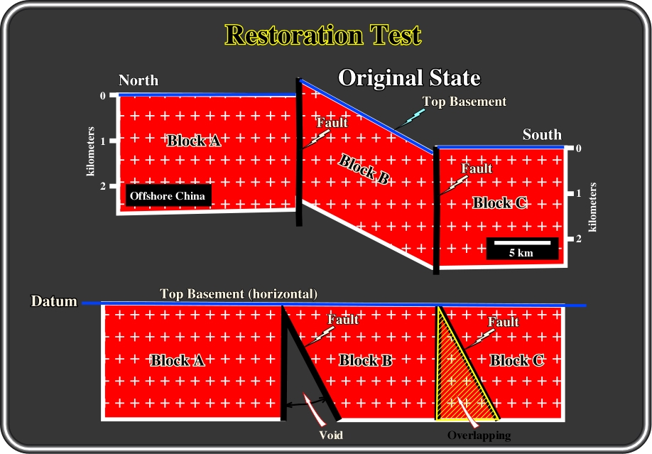
Fig. 34- Indeed, when trying to restore the above cross-section at top basement, it is quite evident that the vertical fault planes cannot be restored without creating huge voids and overlaps of volume. Conversely, one cannot create from the original state a group of tilted blocks with vertical faulting because of the creation of empty space or overlaps. In a fact, all geologists know, or should know that normal faults (1 vertical) lengthen the sediments, while reverse faults (1 horizontal) shorten the sediments. Subsequently, a normal fault that is vertical (macroscopic scale) is theoretically needless, since it does not lengthen or shorten. In addition, there is not space available to allow for downward vertical displacement. In other words, when in the ground, or on a seismic line, the limit between two fault blocks is vertical and ample enough, the fault is all likelihood a strike-slip fault. Apparently, a uniformly sheared fault zone can create tilted blocks with translational movements between the two blocks. However, it is not plausible that a series of sediments above the shear zone can be draped without showing the faulted nature of the tilted block (Arbenz, 1968).
Example 2)
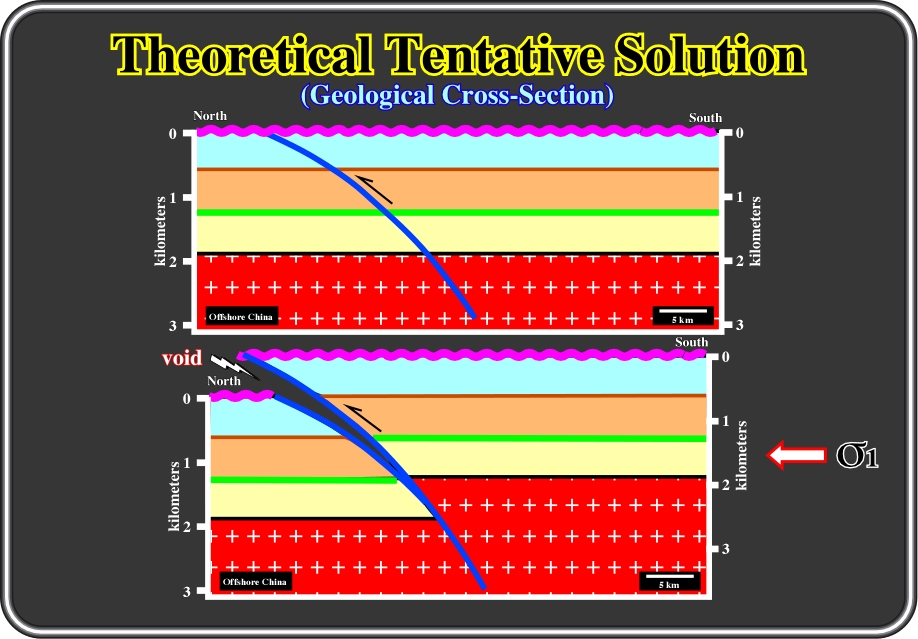
Fig. 35- As we will see later, non-cylindrical faults are mechanically unsound, certainly over lengthy portions of the fault surfaces. Indeed, all curved faults that are non-cylindrical cannot move without further adjustment in one or both blocks since the body forces of crustal material cannot sustain voids. As illustrated, the upward movement of the hangingwall creates a potential void. Subsequently, an adjustment is required, since Nature hates empty space. Two different ways of fill the space created by the fault plane geometry are illustrated in next figure.
Example 3)
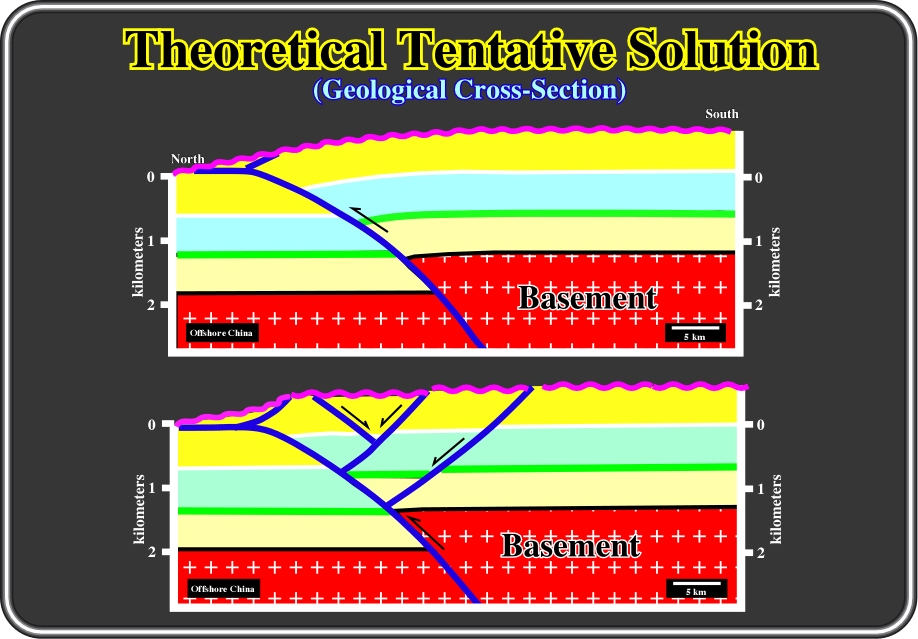
Fig. 36- Here, two tentative solutions to solve the volume problems generated on the previous example (Fig. 35) are illustrated. On the upper solution, the volume problems are solved by folding of adjacent crustal segments, while, on the lower solution, additional normal faults will avoid the formation of voids or superposition of volumes. Indeed, we can say that sedimentary shortening induces uplift, and so, creates potential voids. As a result, the sediments must be lengthened, by normal faults, to fill the space created by folding. Seismic interpreters must know of these kinds of potential adjustments, a priori. Theory precedes Observation (K. Popper, 1934). Indeed, interpreters will be obliged to impose such adjustments to keep the coherence of their tentative solutions. Indeed, due to seismic resolution and seismic processing, for instance, the non-evidence of a fault, on a seismic line, cannot be a proof of its absence on the ground. In other words, interpreters can use the "argumentum ad ignoratiam" in their interpretations. They can argue for presence of the accommodation faults on the basis that there is no evidence against them, whereas to establish that they do not exist they need to show evidence of their absence.
Example 4)
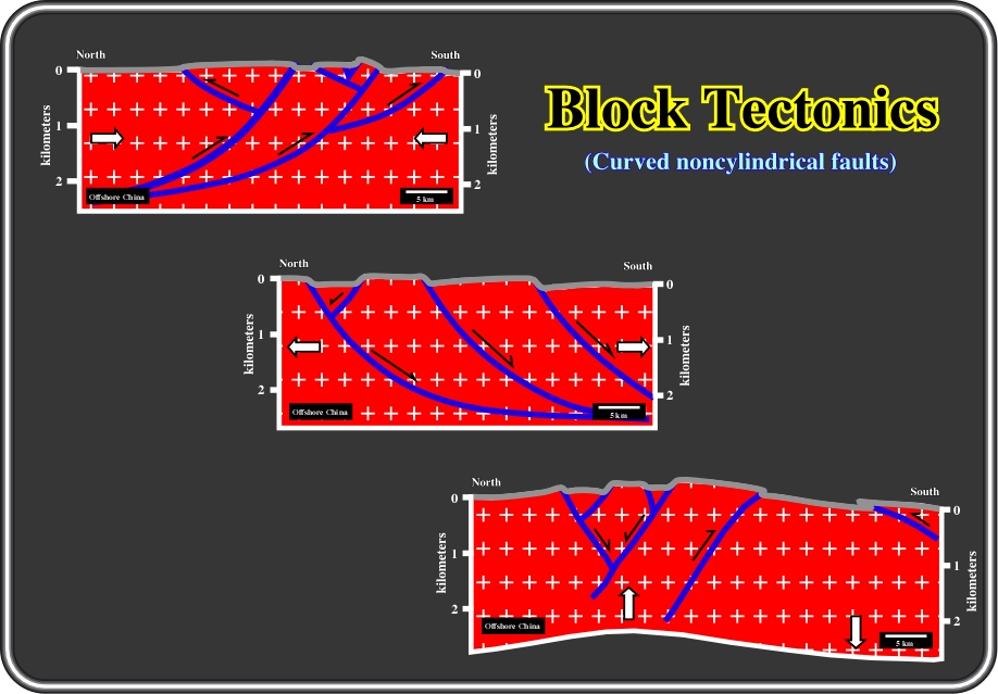
Fig. 37- The block tectonic response to solve volume problems of non-cylindrical faults to common crustal stresses can be grouped into three main types: (i) Compressional, in which reverse faults accommodate the sediments to the new volume conditions, (ii) Extensional, in which normal faults lengthen the sediments in order to fill the space created by extension and (iii) Differentially vertical, where due to differential uplift, normal (with few reverse) faults accommodate the sediments to new volume conditions. During their professional carriers, explorationists are going to be obliged to use these techniques in their tentative solutions in order to avoid an immediate refutation of their interpretations. An acquainted explorationist, on this subject, knows quite well that geological data (seismic, subsurface, gravimetric, etc.) cannot verify or validate a tentative solution. It can only refute it. Notice that in English, verification, validation, confirmation and refutation are not synonyms (Naomi, O., et al, 1994).
to continue press
![]()
Send E-mail to ccramez@compuserve.com or cramez@ufp.pt with questions or comments about this short-course.
Copyright © 2000 CCramez
Last modification:
Agosto 27, 2006