Porto, Portugal
Contents:
5.2- Basement not Involved
       5.2.1- Evaporitic mobile substratum
                5.2.1.1- Compressive décollement structures
                5.2.1.2- Extensive salt structures
                            5.2.1.2.a- Basic Principles in Salt Tectonics
                            5.2.1.2.b- Origin of a dome
                            5.2.1.2.c- Evolution of dome's flanks
                            5.2.1.2.d- Faults associated with domes
                                           A) Stretch faults
                                           B) Growth faults
                            5.2.1.2.e- Evolution domes and residual structures
                                          (i) Structural changes in the salt
                                              A. Mature domes
                                              B. Bottom pinchoff
                                              C. Overhang
                                         (ii) Structural changes in sediments
                                              a) Collapses
                                              b) Turtle structures
                                              c) Haggis structures
                                              d) Raft Tectonics
                            5.2.1.2.f- Review of salt dome growth
                                          A) Mounded Stage
                                          B) Dome Stage
                                          C) Post-dome Stage
                           5.2.1.2.g- Potential reservoirs and traps
                           5.2.1.2.h- Post-sedimentary halokinetic movements
5.2.1. Evaporitic mobile substratum
5.2.1.1- Compressive décollement structure
In spite of the fact that the density of the salt is roughly constant in depth (around 2.15 to 2.17 depending on the amount of magnesium), salt can be deformed as any other rock (fig. 225). However, when the basement is not involved in the deformation, sediments and the salt can be detached and deformed from the bottom of the evaporitic layer, which works as a décollement surface).
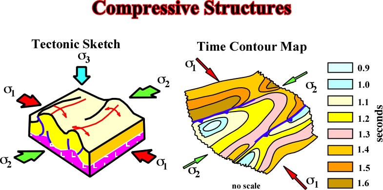
Fig. 225- The salt and cover can be shortened independently of the substratum. All kind of compressional structures can be developed as illustrated on the following figures (fig. 226 to 228).
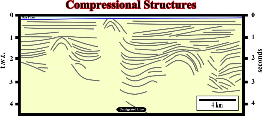
Fig. 226- Several compressional salt structures (anticlines, reverse faults), detached from the basement can be recognized on this seismic line from south onshore France.
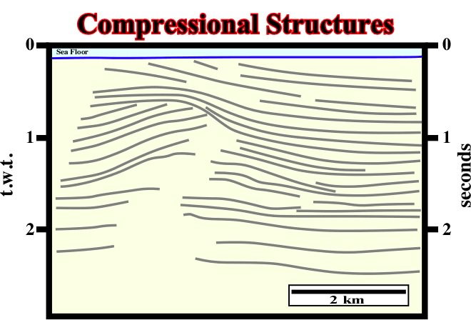
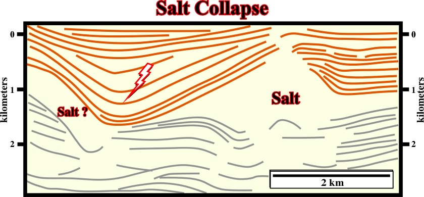
Fig. 227- A major tectonically enhanced unconformity separates two tectonic realms. The older one was compressional. The salt layer and its cover were strongly shortened and uplifted creating a major erosional surface, which underlies a significant stratigraphic cycle boundary. In this particular line, it is difficult to see is the basement is or not involved on deformation. Notice that on seismic lines the bottom of the salt layer usually shows a velocity anomaly (pull-up).
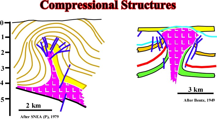
Fig. 228- Typical examples of compressional salt structures are known in Aquitaine basin (Eocene compression) and in South North Sea, where reverse faults develop in post-salt intervals.
5.2.1.2- Extensive salt structures
Lengthening can be associated to a tectonic stress positive, where salt ridge are developed parallel to regional
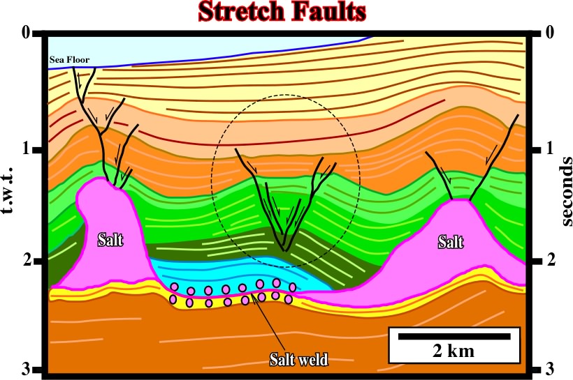
3. Local stresses in the apex of salt ridges can create stretch faults parallel to the ridges (fig. 229). However, this type of deformation is more a geological curiosity than a general salt tectonic movement.
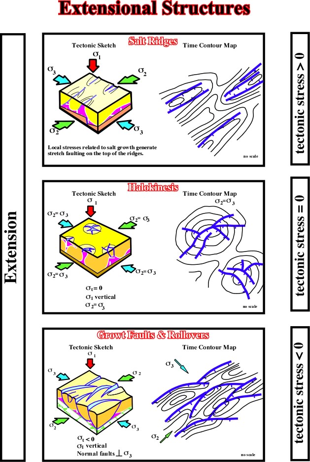
Fig. 230- With a tectonic stress nil, i.e., in absence of a major tectonic stage, the halokinetic movements can be very important. Usually they are synchronous of sedimentation, and so, they can partially control the facies and thickness of sedimentary units. With a negative tectonic stress, salt movements can produce salt ridges parallel to regional
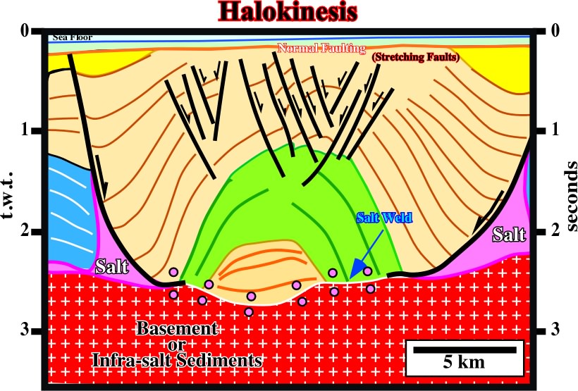
Fig. 231- Halokinesis takes place when tectonic stress is nil. Indeed, as illustrated on this seismic line, the pristine geometrical relationships where completed deformed by salt flowage, i.e., original onlap became apparent downlaps. The evaporitic layer became almost exhausted (salt weld). Salt is just recognized filling the lower part of the normal faults bounding the inverted depocenter.
5.2.1.2.a- Basic Principles in Salt Tectonics
The basic principles in salt tectonics are:
1- Salt can behave as plastic material.
2- Salt deformation starts beyond a certain threshold (100-150 bars depending on the nature of the salt).
3- The density of salt does not vary with depth (± 2.15 / 2.17).
4- A thick salt layer can be divided, from bottom to top, into several levels:
(i) Plastic, (ii) Consolidated elastic, (iii) Slightly consolidated.
5- Salt can either be dissolved at the surface or leached in depth. This is often mentioned to explain anticline structures interbedded with deformed sediments.
6- Whenever a salt level is covered by a layer of sediments whose average density exceeds that of the salt, there is a mechanically unstable situation.
7- If the difference in pressure between two not very distant points, within a salt layer having plastic properties, is zero, there is no salt movement.
8- There will be salt movement if there is difference in pressure between two not very distant points. However, salt movement occurs only when the force F created by the difference in pressure (deltap) between these two points must be great enough to overcome:
a) Friction at the base of the salt.
b) Resistance of the sedimentary cover.
The difference in pressure can be due to:
a) Variable thickness of the sedimentary column.
b) Variable lateral density of sedimentary column.
c) Post-salt tilting.
9- When the top of the salt layer has a dip, the salt moves in a direction that depends on the average density of the sedimentary overburden.
a) When the average density of the overburden is lesser than the density of the salt, the salt moves downdip.
b) When the average density of the overburden is greater than the density of the salt, the salt moves updip.
10- The pressure gradient (deltaP) causing salt movement depends only on the dip (alpha) of the top of salt.
11- The morphology of the bottom of the salt layer (assume to be regular) is practically negligible in the salt movement.
12- Above the salt compact beds as limestone or sandstone, rigid in appearance, are readily fractured by traction. The compressive strength and tensile strength of an overburden are very different.
If a small anomaly exists at the top of the salt (small mound) and the overburden layer is relatively thick, the salt flows toward the crest of the anomaly creating a dome. On the other hand, irregularities on salt-overburden interface produce small slopes (anomalies) at the surface of the salt. The mechanism remains the same even if the irregularities at the top of the salt have a small amplitude. Smaller they are longer it takes to develop a dome. Then, as soon as an anomaly is formed, it produces a chain reaction, i.e. other domes develop on each side of the syncline.
Fig. 232- Different morphologies of the salt structures are easily recognized in Gabon Offshore. The linear geometry, recognized in the southern part suggests (i) the irregularities on the salt surface are controlled, or (ii) salt tectonics mechanism is different of the described above.
In a flat geological environment the irregularities of the salt surface have a random spatial distribution, that is to say, most of the salt structures have a circular rather than linear geometry, i.e. salt domes are more frequent than salt ridges.
5.2.1.2.c- Evolution of dome's flanks
(i)- When the sedimentary layers deposited between the domes are thick enough, the average density of the sediments is greater than the density of the salt. The overlying sediments are denser that the salt, e.g. limestones.
(ii)- The weight of the sedimentary column forces the salt migrate towards the crest of the dome.
(iii)- The thicknesses of the overburden layers decrease from the flanks towards the top of the dome, as illustrated in fig. 233.
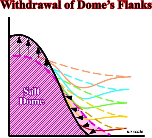
Fig. 233- As the salt moves from the flanks toward the crest of the dome, prekinematic sediments collapse and a local compensatory subsidence is created. Synkinematic sediments are thicker on the flanks than on the top of the dome.
(iv)- The force causing the salt to migrate decreases from flanks towards the top.
(v)- The thicker the post-salt sedimentary column, denser the sediments are and greater is the force causing salt migration.
In conclusion:
The force acting upon the salt is greatest at the deepest part of the salt - overburden interface.
(vi)- The sinking (collapse) of the sediments occurs at the base of the dome flanks when the salt migrates (fig. 234).
Fig. 234- On this seismic line from conventional offshore Angola, the rim synclines (depocenters) around the salt dome strongly suggest the compensatory subsidence, induced by salt flowage) is greater in the deepest part of the interface salt-overburden.
(vii)- The withdrawal around a salt dome is not necessarily uniform.
(viii)- The difference in withdrawal around a dome is the result of the nature of the sedimentation (fig. 235).
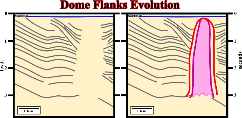
Fig. 235- On this the evolution of the flanks of the dome is different. They are quite asymmetric, particularly the rim synclines. Note that as the line is unmigrated, interpreters have a tendency to increase the wideness of the dome (red picking instead green picking). On the other hand, firstly, it is quite evident that the dome cannot have vertical flanks (mechanical instability), secondly, taking into account the velocity of the seismic waves in the salt, a continuous column (3 seconds, t.w.t.) of salt corresponds roughly to 6-7 km of salt, which seems unlikely.
5.2.1.2.d- Faults associated with domes
There are two major types of normal faults associated with domes:
A- Stretch faults (halokinesis), B- Growth faults (gravity sliding).
Fig. 236- On this regional line of offshore Brasil, growth faults and reverse faults are associated with salt tectonics. However, the reverse faults, located in the distal part of the basin, are associated with a local compressional tectonic regime created as a response to the updip extensional tectonic regime responsible by the growth fault development.
Currie's experiments (fig. 237) illustrate the development of these faults:
A.1- They develop at the top of domes when sediments are not eroded.
A.2- They can be contemporaneous or posterior of sedimentation and dome's growth.
A.3- Their throw is generally small. Quite often they can not be recognized on seismic data. They are often under seismic resolution.
A.4- The sum of the "right" throws (faults facing east) is equal to the sum of the "left" throws (westward vergence).
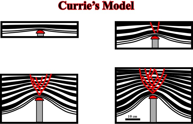
Fig. 237- The layers are lengthened by radial stretching faults as the piston moves upward. When the layers are synchronous of the piston movements, they thin upward. Theoretically, in a cross-section, the sum of the throws with opposite vergence must be roughly zero.
A.5- The geometry can be radial or elongated (fig. 238).
A.6- They establish the chronology of the salt intrusion and the fault movements.
Fig. 238- Generally, stretch faults are radial when associated with domes. When associated with salt ridges and turtle back structures (elongated antiforms) as it is the case on this seismic line, the geometry of the stretch faults is mainly elongated. Indeed, on this seismic line, the stretch faults on the top of the central antiform are induced by the salt flowage toward the top of the ridges,which created a salt induced tectonic inversion.
Growth faults are often located nearby the shelf-continental slope break. They generally become inactive during basinward movement of the shelf-slope break. However, if salt movement continues, their fault planes are deformed.
Growth faults are also recognized in the deepest part of certain basins, as for instance in Mediterranean Sea (fig. 239).
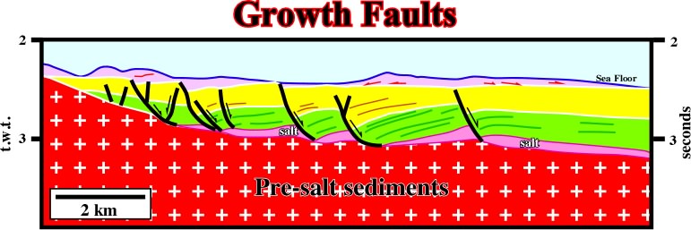
Fig. 239- In deep water Mediterranean Sea, growth is faults induced by flowage of Messinian salt are paramount. As suggested by this seismic line, the salt movement seems to be contemporaneous with the deposition of the yellow interval. The more or less constant thickness of the green interval suggests it is likely a prekinematic layer.
5.2.1.2.e- Evolution of domes and residual structures
In the late stages of a dome evolution, structural changes occur not only in the salt but in adjacent sediments as well.
(i) Structural changes in the salt
If dome growth continues, overlying sediments are deformed by stretch faults. In certain cases, when sedimentary deposition is rapid and not uniform, the top of the dome pierces the sediments. Therefore, mature domes should not be interpreted as salt spines or extrusive domes (apparent diapirism), as illustrated in fig. 240.
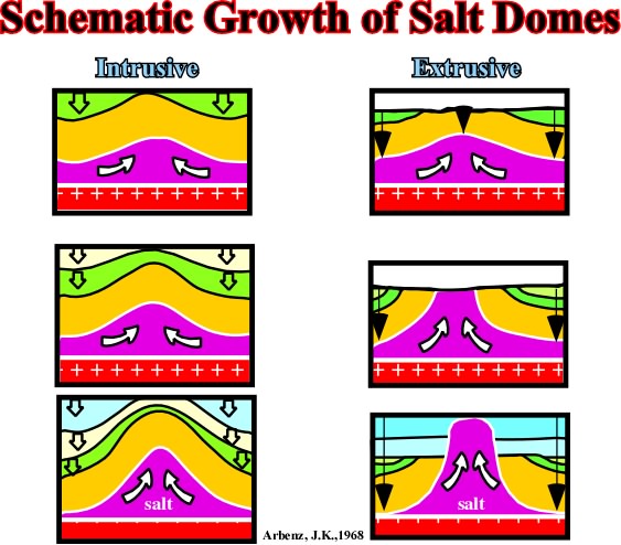
Fig. 240- On this sketch, it is easy to differentiate diapirism (on the left) and apparent diapirism (on the right). In fact, when a salt dome arrives in surface or at bottom sea, if it is connected with the source layer, the salt moves upward as sedimentations takes place. A tectonically enhanced unconformity underlines the salt outcropping. Indeed, below the unconformity, the postkinematic overburden is deformed by salt diapirism, but above it, the synkinematic overburden is undeformed since the salt moves upward at same time that deposition takes place (see fig. 241).
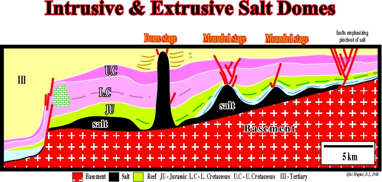
Fig.241- On this crosse section from onshore-offshore Alabama (USA),based on a regional seismic line, the salt layer (in black), which pinchout is underlined by a stretch fault complex, shows different phases of growth. In mound stage, one can say the structures are intrusive, but in the dome stage, they are extrusive with apparent diapirism in the upper layers (Upper Cretaceous and Tertiary).
Seismic examples of an intrusive and extrusive salt structures are illustrated on the next seismic lines
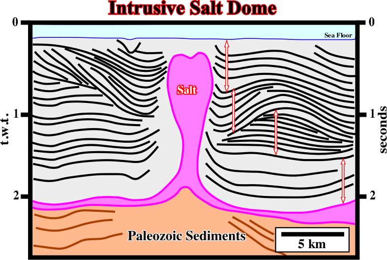
Fig. 242- In this unmigrated seismic line, the limits of the salt are difficult to pick. Nevertheless, the rim synclines of the upper intervals strongly suggest they are synkinematic. The more likely is that the salt is intrusive and probably disconnected of the mother source layer. The enhanced unconformity seems to be associated with the beginning of the salt flowage inducing significant compensatory subsidence and not with the arrival of the salt in surface as it is the case in the line below (fig. 243).
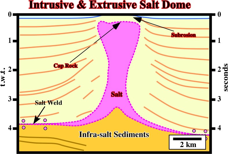
Fig. 243- On this line the flanks of the salt structure are also quite difficult to pick. Nevertheless, the deformation of the lower overburden contrasts with the undeformed or slightly deformed upper overburden. The unconformity bounding deformed and undeformed overburden underlines the limit between intrusive and extrusive situation. So, one can say the upper salt shows apparent diapirism.
In the first stage of dome growth, the slope of the interface salt-sediment is not too steep and we can assume the salt and sediments behave as viscous fluids (horizontal stress which they exert is equal to the geostatic stress). In the most advanced stages (nearly vertical flanks), the horizontal stress exceeds the geostatic stress. Below a certain depth (where the angle of equilibrium is vertical) the sediment pressure across the vertical interface exceeds the counterpressure of the salt. The result is an overturning of the salt-sediment interface, process which leads to a pinching-off of the dome near its base (fig. 244 and 245).
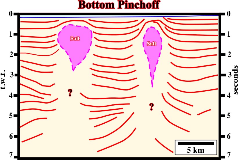
Fig. 244- Likely, on this seismic line the allochthonous salt structures are disconnected of the mother salt layers. A vertical salt weld is probably present. We guess the salt arrives to bottom of the sea and started to move upward under an apparent diapirism. Then, when ii became disconnected of the mother layer (horizontal salt welds), the upward movement of the salt created a secondary vertical salt weld.
Fig. 245- Be always sure that the geometry illustrated on a seismic line is representative at 3 dimensions.. This is particularly true in basins with allochthonous salt layers. In fact, the structure illustrated on this seismic line is not a bottom pinchoff as illustrated in previous figure. Indeed, it illustrated a section of a salt nappe intersected by a strike seismic line( transverse to the allochthonous salt displacement).
So far, we have assumed implicitly that a salt structure develops an equilibrium shape at all levels. This is not always true. Thus:
- If a vertical salt-overburden interface, in equilibrium at a certain depth, is elevated, the equilibrium is disrupted.
- In its new position, the salt will exert more pressure on the sediments than the sediments exert on the salt. The result is a overhang structure (fig. 246).
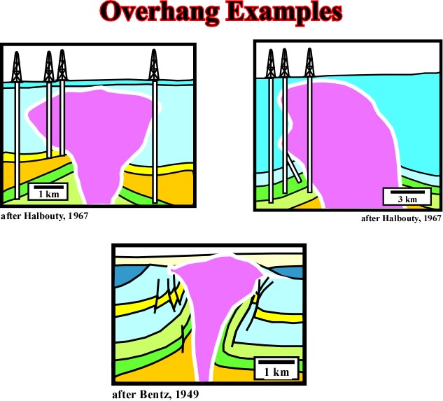
Fig. 246- Overhang examples after different authors. Note that in certain condition reverse, or apparent reverse faults can be developed in association with overhang geometries (see seismic examples below).
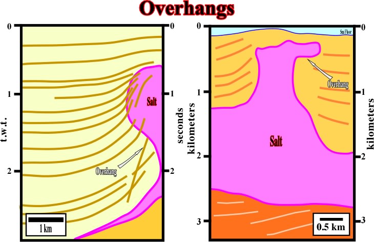
Fig. 247- Two examples of overhangs in time and in depth. The example in depth, coming from Gulf of Suez is more significant since the salt flow laterally in surface for almost 1 km. The example in time, from Gulf of Mexico, corresponds more to a salt bulk above a stem.
(ii) Structural changes in the sediments
In the maturation stage, all the flanks, even structurally high flanks, collapse into the void created by the withdrawal of the salt which supported them as illustrated in fig 248.
Fig. 248- The lateral flowage (salt withdrawal or salt collapse)of the salt created a local compensatory subsidence, which explains the depocenter overlying an old salt induced structural high. Between salt collapses interesting antiform structures can be developed as depicted in fig. 249.
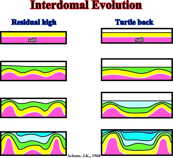
Fig. 249- As illustrated antiform structures, that is to say extensional structures can be developed between rising salt domes. Often, residual salt structures can be found in the heart of the interdomal structures. When salt expulsion is total, salt welds are created below the salt induced inverted antiforms.
Note that salt over a flat substratum with enough thickness, i.e. more than 500 meters, can flow without overburden.
Residual structures that develop in the interdomal areas when all, or part of the salt, is removed (fig. 250). These structures are formed in the following way:
a) The depositional sequences prior to salt migration become thicker toward the center of the synformes.
b) They become thinner, converging toward the domes, with parallel or convergent internal configuration.
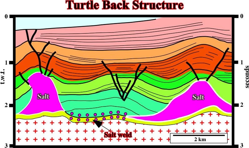
Fig. 250- On this time cross-section (interpretation of a seismic line), an asymmetric turtle back structure, developed between to salt domes, overlies a salt weld. Notice that the sediments associated with the brown interval strongly thick above the right dome. Such a thickness variation suggests the right salt dome was reactivated inverting the depocenter. The reactivation can be salt or tectonically induced. The apex of the turtle back structure was clearly extended by stretching faults.
c) As salt begins to migrate, i.e. to flow away from the base of the dome, the structurally high sequences collapse.
d) Their new structural position is low compared with the stratigraphic equivalents in the center of the interdomal area.
In conclusion:
The beds initially in a low structural position, become structurally high, and at the same time those which were high become low (fig. 251).
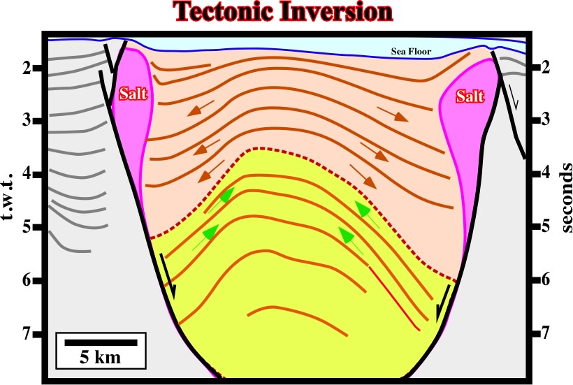
Fig. 251- Taking a look for the thickness of the seismic packages, it is quite easy to recognized the tectonic inversion and its timing. A major unconformity underlies the onset of the salt induced tectonic inversion. Before the inversion, the sedimentary intervals thick inward. Since inversion takes place, the sedimentary intervals thick outward, in direction of the salt domes, creating rim synclines.
When exploring for hydrocarbons on this type of structures as well as on those associated to marginal collapses, explorationists must know the geological history of the area (fig. 252), and in addition they must know in detail in detail:
(i) the inversion time, (ii) the maturation, (iii) the migration's time.
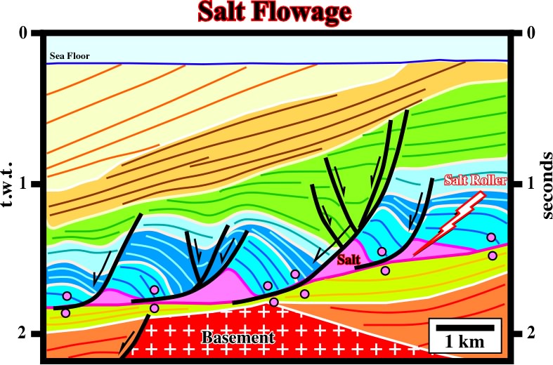
Fig. 252- On this line of the conventional Angola offshore the tectonic disharmony associated with the bottom of the salt layer is easily recognized; above it the sediments are significantly deformed, while below, rhey are roughly undeformed. The normal faults associated with the salt flowage can also be easily picked when taking into account the reflection terminations (seismic surfaces). The onset of salt flowage is underlined by an unconformity characterized by sedimentary intervals with internal configuration divergent above, and sediments with parallel internal configuration below.
Haggis structures are the final configuration of a succession of inter-domal structures when the stretching due to a tilting results in a complete flattening of the salt domes (fig. 253).
In the final stage of this evolution, we can observe a succession of:
- Turtle-back structures separated by
- Mounds of stretched salt.
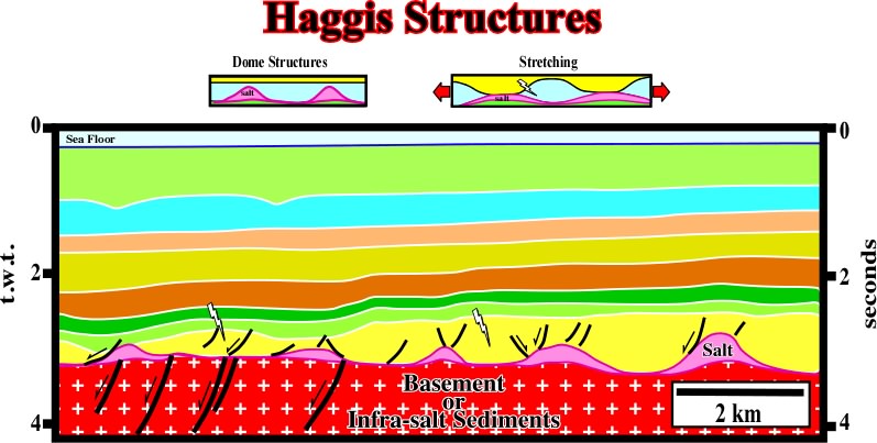
Fig. 253- As the name suggested, Haggis structures are inverted depocenters induced by a almost total salt reduction, This structures are quite frequent in North Sea and some of them have been drilled for hydrocarbons. The timing of inversion in relationship to the hydrocarbon migration time is an exploration key parameter.
The mechanisms described so far (conventional salt tectonics) do not provide an explanation for all the types of structures which exist in the salt basins (fig. 254), as for example in the Kwanza and South Congo Basins (offshore and onshore Angola).
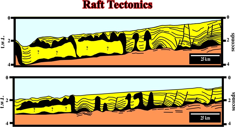
Fig. 254- The geological interpretation of the old (1968) seismic lines of the Northern Offshore Angola, raft tectonics ("Tectonique en Radeaux") is paramount. Several mechanisms have been propose to explained the morphology of the Tertiary depocenters and associated Cretaceous antiforms (fig. 255).
Indeed, the morphology of Tertiary depocenters cannot be explained by conventional salt tectonics. In 70s, TOTAL (Burollet, 1975) suggested a raft tectonic mechanism as illustrated in fig. 255.
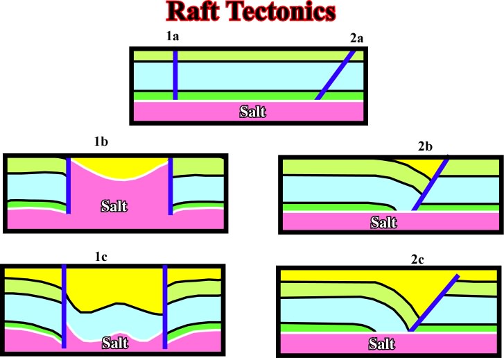
Fig. 255- Assuming a seaward gliding of a faulted overburden different kind of depocenters (in yellow) can be developed. A generalized seaward tilting of the cover (salt + overburden), often associated with the breakup of the Pangea lithosphere, must be taken into account.
This kind of salt tectonics implies, as depicted in the previous figure, the following sequence of geological events:
(i) salt deposition;
(ii) deposition on the prekinematic overburden;
(iii) fracturing of the prekinematic overburden due to early salt tectonics;
(v) gliding of the overburden;
(vi) filling of potential voids by depocenter of recent sediments;
(vii) continued seaward gliding of the overburden and evolution of the depocenter in relation to the geometry of faulting (fig. 256).
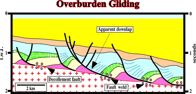
Fig. 256- The seaward gliding of the cover (salt + overburden) seems evident. The prekinematic overburden (light yellow interval) shows a slightly regional landward thickening, while the synkinematic overburden shows a strong landward thickening against the listric fault planes. Notice the formation of small fault welds between the salt rollers.
Salt tectonics can develop structures with or without residual salt, as illustrated on the following lines of Offshore Angola (fig. 257).
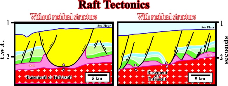
Fig. 257- On the left seismic line (zoom in fig. 258), there is no residual salt, between consecutive faults, while on the other line (zoom in fig. 259), there is a residual salt structure. Note that in this kind of halokinesis, where sliding displacement.
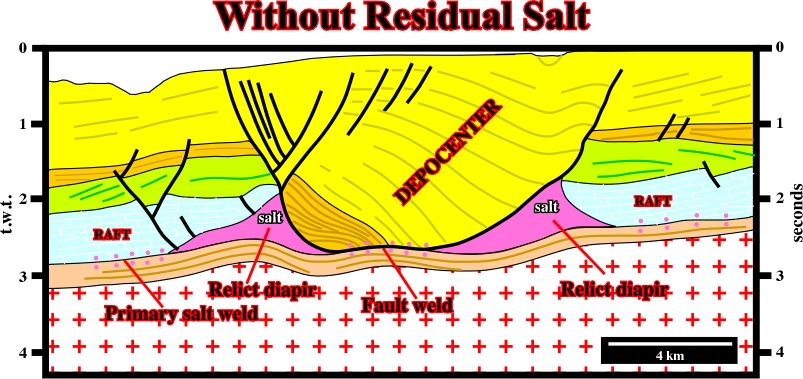
Fig. 258- The bottom of the depocenter (see fig. 257) is composed by sandstones, while the upper part (in yellow) in mainly formed by shales. No residual salt is recognized within the depocenter.The depocenter lies between two Lower-Middle Cretaceous rafts. A fault weld as well as primary salt welds underline the bottom of the evaporitic layer. Below the tectonic disharmony associated with the bottom of the evaporitic layer the infrasalt sediments are undeformed. The slightly undulations are pull-ups induced by the salt.
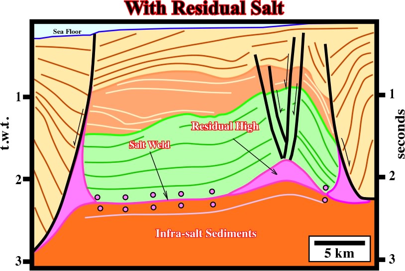
Fig. 259- On this line (see fig, 257), a residual salt structure ( raft) is evident below the Tertiary depocenter. The tectonic disharmony associated with the bottom of the evaporitic layer, characterized by sat and fault welds, is quite evident. The overlying sediments are deformed (lengthened), while the underlying are undeformed. Notice how the dip of the fault planes changes with the lithology.
5.2.1.2.f- Review of salt dome growth
During the evolution of a salt dome, three main stages can be considered:
(i) mounded, (ii) dome and (iii) post-dome.
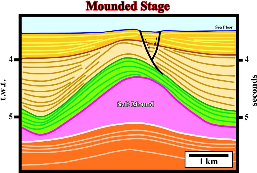
Fig. 260- A salt mound is easily recognized on this seismic line of deep Mediterranean Sea. Notice the pull-up induced by the lateral variation of the salt.
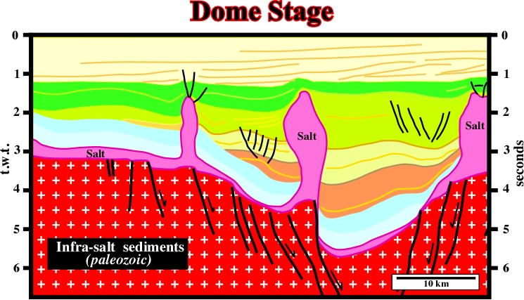
Fig. 261- In this interpretation of a North Sea seismic line, salt diapirs are evident. They seem to be localized in particular areas of the substratum in association with major faults. However, the age of the faulting in not very clear. In our opinion, the faulting is not pre-salt, but post-salt and roughly equivalent to the age of the brown depocenter. In other words, in the Cretaceous time, the basement (paleozoic) and the cover were lengthened by a regional tectonic regime and so preexistent fault of the basement were reactivated.
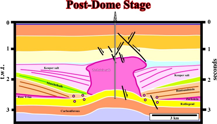
Fig.262- In this stage, notice the amplitude of the rim synclines, limiting the salt walls, and the overhang. See how the thickening of the synkinematic layers is in opposite direction. The tectonic disharmony and the pull-up induced by the salt are quite evident.
These stages are synchronous with the sedimentation, which is partially controlled by salt tectonics. The halokinetic movements are contemporaneous with the strata, which facies can be easily predicted, as illustrated by the geological models below (fig. 263 to 265).
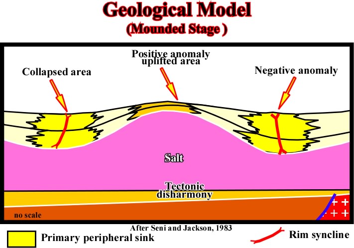
Fig. 263- In a mounded stage the potential sandy reservoir will be deposited in the areas with maximum compensatory subsidence, i.e. in the troughs.
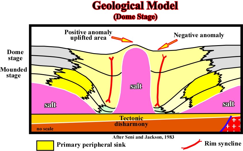
Fig. 264- The upward salt flowage induces a strong compensatory subsidence, which creates large rim synclines limiting the salt. A migration of the depocenters toward the walls of the diapir is evident. However, as said previously, a vertical geometry of the wall of a salt structure is an unstable geometry. It has a tendency to evolve in a post-dome fracturation.
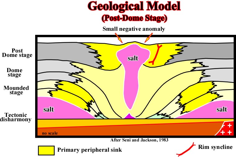
Fig. 265- Notice the displacement of the depocenters toward the wall of the post-dome structure. Generally at that stage the salt bulk is disconnected not only of the mother source layer but from the stem as well.
5.2.1.2.g- Potential reservoirs and traps
Taking into account the previous geological models of the different stages, few hypotheses can be advanced on the more likely potential reservoir and trap locations. They are illustrated in the figures below.
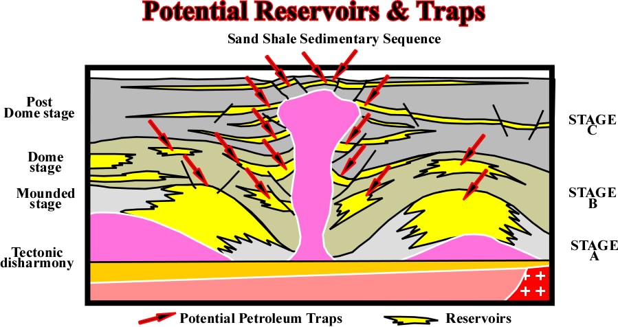
Fig. 266- The potential reservoirs are located in the deep part of the depocenters, where thickness, sandstone pinchouts or stratigraphic traps.
To avoid dry wells in oil bearing provinces, a special attention must be paid to:
(a) time of hydrocarbon migration and (b) age of the structural traps.
If hydricarbon migration occurs during pre-dome stage, the turtle-back structures, developed during dome stage, are not good targets. Their structural highs are younger than hydrocarbon migration. Hydrocarbon dysmigration is necessary to find an oil accumulation. The same criterion is valid for carbonate sedimentary sequences (fig. 267).
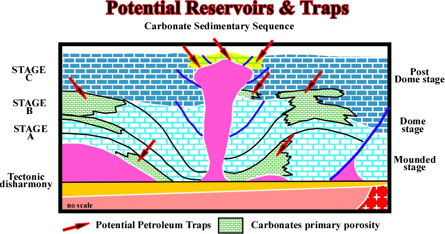
Fig. 267- Contrariwise to the sand-shale intervals, in carbonate sequences, as illustrate above, the ppotential reservoirs are located mainly in the old structural high points where the environment energy favours the development of porous carbonates. The more likely potential traps are associated with changes in facies and morphologic trpas either by juxtaposition or stratigraphic.
In sedimentary carbonate sequences, associated to halokinetic movements,one can find good reservoir rocks and petroleum traps in structural lows. Actually, they were high structural high before the tectonic inversion produced by salt flowage.
5.2.1.2.h- Post-sedimentary halokinetic movements.
Good examples of post-depositional salt movements have been described in Gulf Coast Basin (fig. 268), where the evaporitic layer has been admitted to be active during Jurassic time (Norphlet-Smackover formations) and then during Plio-Pleistocene time with development of salt spines structures. However, as illustrated in the figure below, the geometry of the spines flanks seems to be more related to a seismic artefact than a really interface sediments-salt.
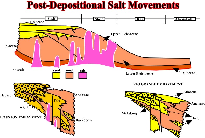
Fig. 269- Salt domes with vertical wall are mecdhanically instable. Indeed, as the densiti of the salt is constant in depth, there is always an inversion point. Above it the preesure of the salt against the sediments is higher than the pressure of the sediments against the salt. So, the salt flows laterally. Contrariwise, below the inversionpoint, the pressure of the sediments against the salt is much higher than the pressure of the salt against the the sediments, subsequently the salt flows upward. In other words, the majority, if not all bibliographic examples of vertical salt domes, as those here illustrated, are probably far from the reality.
Post depositional halokinetic movements, particularly those associated with allochthone salt, are too complex to be studied here. They will be objet of another workshops.
press here
next
![]()
Send E-mail to ccramez@compuserve.com or cramez@ufp.pt with questions and comments about these notes.
Copyright © 2001 CCramez
Last update: March, 2006
.jpg)