
Porto, Portugal
Contents:

6.1- Concept of Salt Welding
6.2- Types of Salt Welding
       6.2.1- Primary Welds
       6.2.2- Secondary Welds
       6.2.3- Tertiary Welds
6.3- Recognition of Salt Welds
6.4- Salt Weld and Fault Weld
6.5- Translation Onlap Surfaces
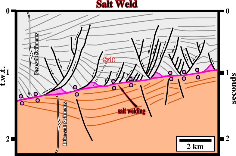
A salt weld is a surface separating two stratal units formerly separately by salt and now in contact, as illustrated in fig. 183.
There are three types of salt welds:
(i) Primary Welds,
(ii) Secondary Welds and
(iii) Tertiary Welds
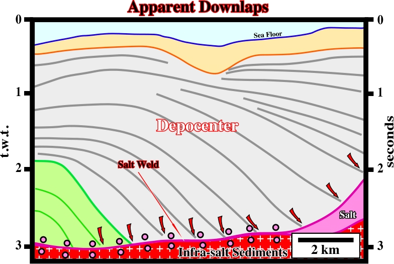
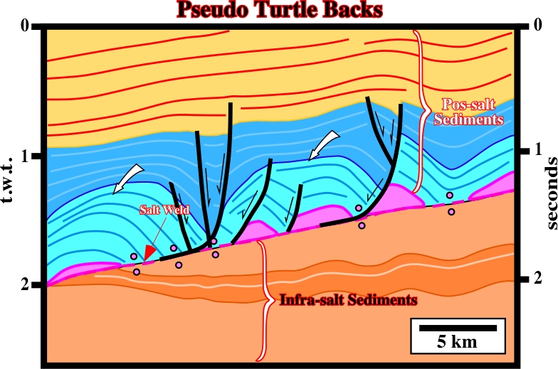
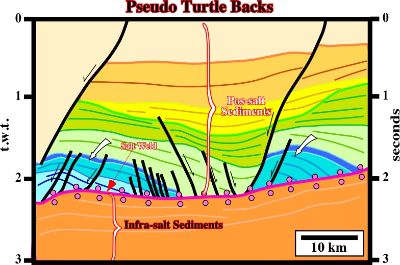
Primary welds join strata originally separated by autochthonous salt (fig. 184). The welds are generally gently dipping. Joining regional dipping sub-salt strata with supra-salt sediments (overburden), which, locally, dip more steeply, creates a tectonic disharmony, which may look like an angular unconformity (fig. 185). Dip is locally enhanced by rotation due either to listric faulting or salt withdrawal below lapouts. Pitfalls produced by this process are: (i) Apparent downlaps (fig. 186 and 187) and (ii) Pseudo-turtle back structures (fig. 188 and 189). The associated disconformity is enhanced by rotation of the overburden creating apparent downlaps. The original onlaps are tilted, generally, landward as salt withdrawal.
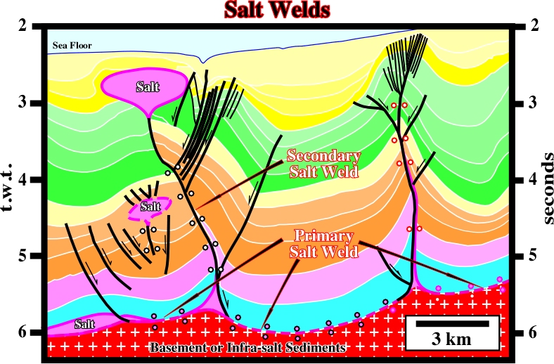
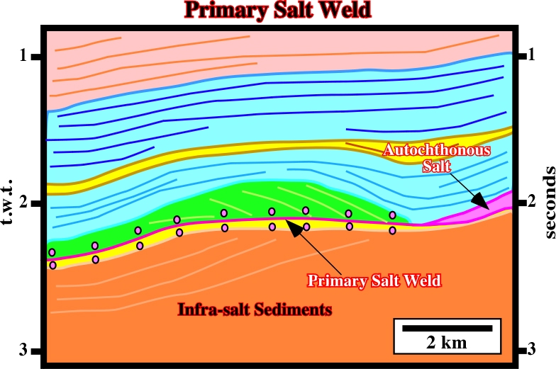
Fig. 185- The salt weld, created by the salt withdrawal of autochthonous salt, is highlighted by the small pink circles. On the right side of the line, autochthonous salt is seismically present. At the bottom of the overburden, the pristine onlap geometry of the seismic markers was deformed into apparent downlap reflection terminations.
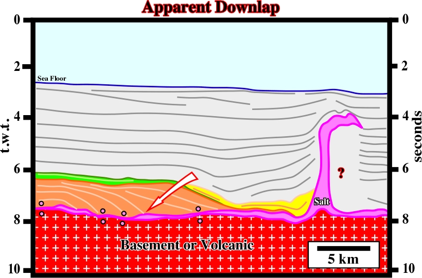
Fig. 186- The brown interval does not correspond to a progradational sedimentary package. The refection terminations do not define a downlap seismic surface. The seismic markers were deformed, and tilted eastward, due to salt flowage, which is also responsible for the allochthonous salt visible on the right side of the line. In the 80’s, the majority of the geologists working in the GOM interpreted the brown interval as the seaward progradation of the Cretaceous shelf break.
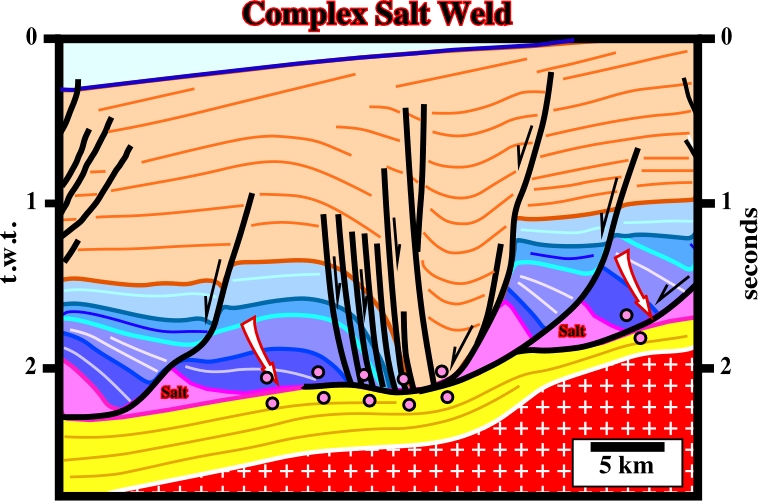
Secondary salt welds join strata originally separated by steep-sided salt diapirs (walls, stocks, etc.), and are near vertical or are steeply dipping. The salt feeding a spreading bulb or allochthonous sheet causes the diapir stem to laterally shrink: (i) eventually thinning to negligible width or (ii) pinching off entirely (fig. 190), often by varying amounts of contraction.
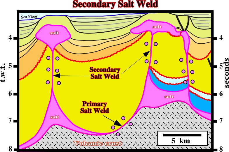
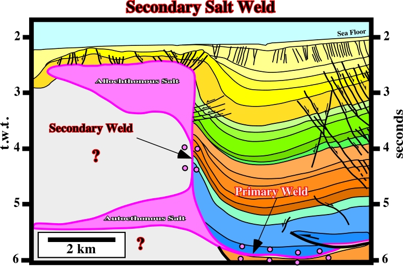
Fig.191- A secondary salt weld separates the allochthonous salt from the allochthonous layer.
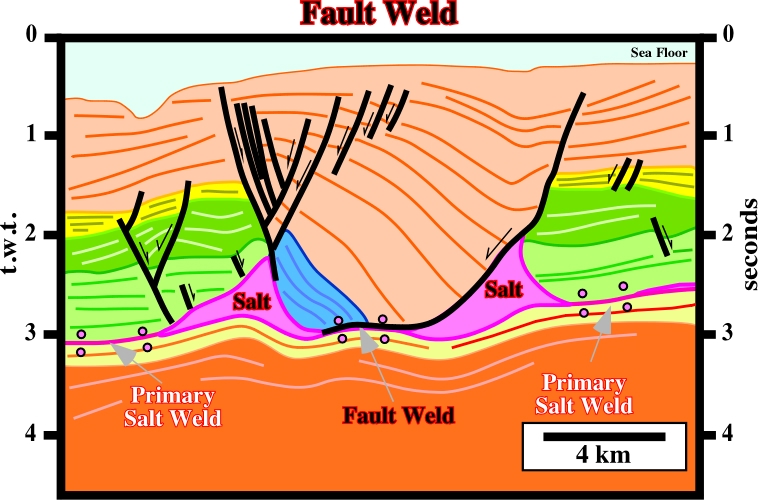
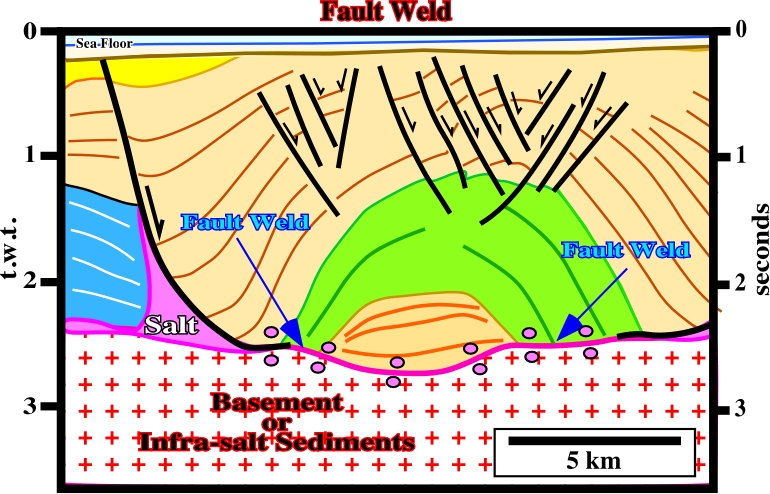
The cover flanking each side of a diapir can then join discordantly together because diapiric growth is usually asymmetric. In such case, the salt weld resembles a growth-fault whether or not such a fault localized the formation of the diapir. This type of weld is often called fault weld.
Tertiary salt welds (fig. 194 and 195) join strata originally separated by a first order or higher allochthonous salt sheet (canopies, tongues, nappes, sills, etc.).
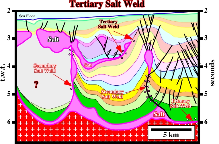
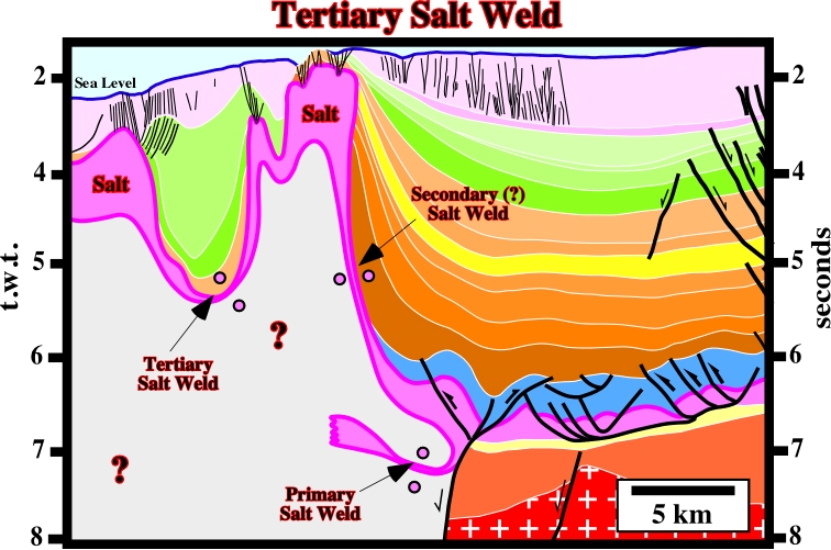
Tertiary welds are generally shallow dipping. They are typically discontinuous and inserted at unpredictable stratigraphic and structural levels. They are particularly useful to mark the former position of allochthonous salt sheet. Tertiary welds are generally overlain by highly extended cover and may be fronted by shortened strata, what leads to complex mixture of structural features on each side of the salt weld.
6.3- Recognition of Salt Welds
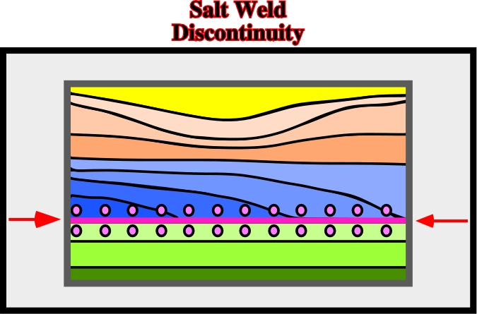
The recognition of a salt weld, as schematized on fig. 196, is quite important to understand the geology of salt basins and the associated petroleum systems.
A salt weld is a surface joining rock volumes formerly separated by salt as illustrated in fig 198.
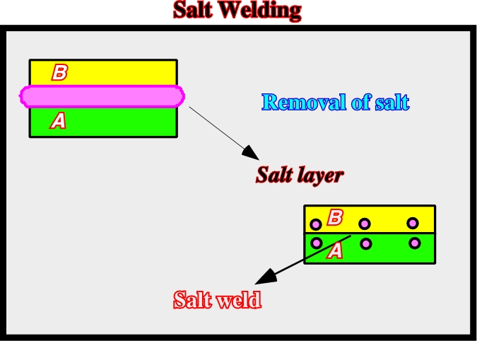
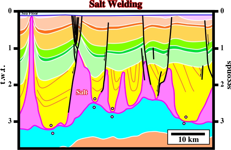
Fig. 199- In spite of the geometry of the synkinematic layer (in yellow), the salt welds recognized on this line do not involve a significant lateral displacement. Wells found a thin salt interval (under seismic resolution) on the welds.
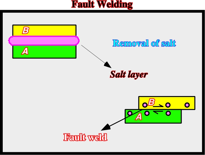
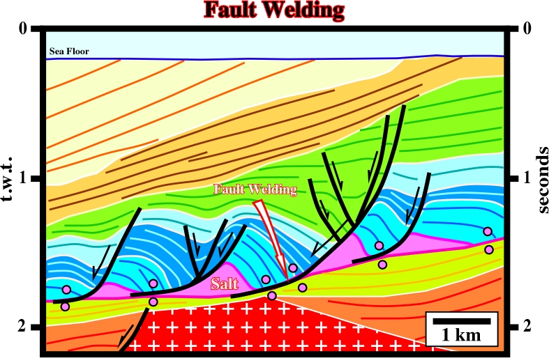
Fig. 200- As previously (fig. 198), in a fault weld, which implies a relative lateral displacement between the overburden and the sub-salt strata, the salt removal is related to seismic resolution (fig. 201).
6.5- Translation Onlap Surfaces
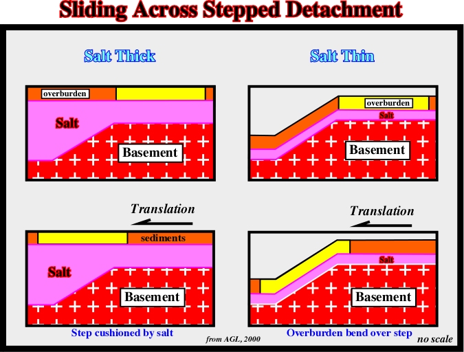
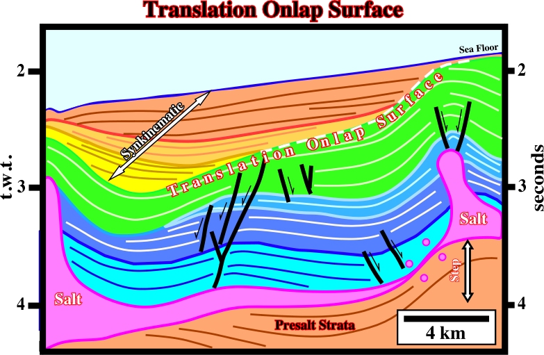
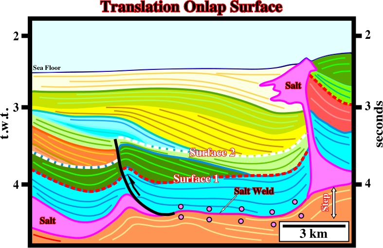
Translation of the overburden across a stepped salt detachment (thin salt) bends the post-salt sediments and can create apparent translation downlap surfaces (gliding onlaps) in the synkinematic layers (fig. 202 to 205).
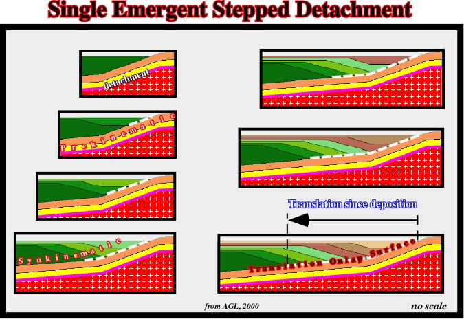
Summing up, the key points of overburden translation over a single buried step can be summarized as follows:
a) If the sedimentation rate is insufficient to cover the bathymetric escarpment, each unit will onlap above the step.
b) Onlaps are translated basinward after deposition, producing a landward-dipping package of onlapping strata (apparent downlap surface).
c) The distance from a given onlap to the step records the amount of translation since the deposition of that unit.
d) As older depocenters are translated basinward, younger depocenters form at the step. Continued translation produces a shingled series of landward-dipping stratal units, bounded by two growth axial surfaces.
c) The distance between the step and the intersection of a horizon with the landward growth axial surface records the translation since the deposition of that horizon.
d) For a given translation rate, faster sedimentation produces steeper growth axial surfaces.
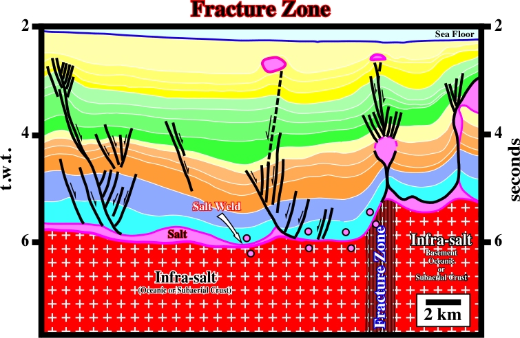
On this subject, it is interesting to note that the salt steps recognized in the offshore Angola (previous examples) seem to correspond to the fracture zones (see later) separating the different geological provinces of the South Atlantic margins. However, the one illustrated on the seismic line below (fig. 206), apparently does show any evident translation onlap surface.
to continue press
next
![]()
Send E-mails to ccramez@compuserve.com or cramez@ufp.pt with questions or comments about these notes.
Copyright © 2001 CCramez
Last modification:
Março 19, 2006