Universidade Fernando Pessoa
Porto, Portugal
II- Tectonic Regimes & Volume Problems
b.3) Folding & Faulting Solutions (cont.)
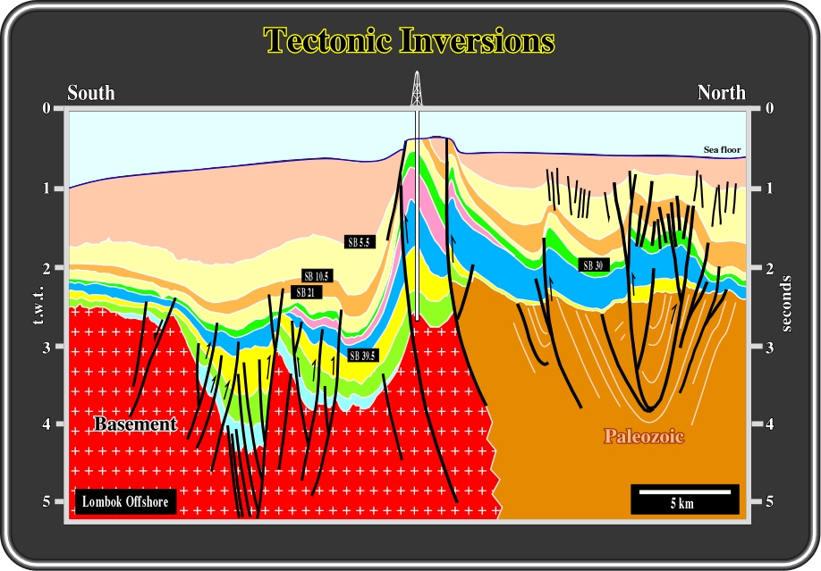
Fig. 57- In this interpretation, volume problems, created during a compressional tectonic regime, are solved by folding and reactivation of the pre-existent normal faults as reverse faults. The normal faults developed during the rifting phase of a back-arc basin during which an extensional tectonic regime was prevalent. In the northern part of the line, the reactivation of the pre-existent normal faults is quite important. The pristine normal geometry changed to reverse. Contrariwise, in the southern part, the reactivation is less important. The geometry of the reactivated reverse faults still is normal. As fault reactivation depends (i) on the angle between
1 of the compressional tectonic regime and the strike of the fault, and (ii) the angle between

Fig. 58- In the northern Venezuela offshore, compressional tectonic regimes are predominant. In fact, this offshore transect is located inside of the Meso-Cenozoic megasuture. The normal faults, predating compressional tectonic regimes, will be sooner or later reactivated as reverse faults. The normal faults created during rifting phases, will be reactivated whether by inversion or buckling in order to solve the volume problems created by the shortening. The picking of the main reflectors of a seismic line of this area, strongly corroborates the previous conjectures. The majority of the reflectors are folded in association with the reactivation of pre-existent faults. The faults are not identified by diachronic reflectors, but by discontinuity breaks of the reflectors. The geometry of the reflectors suggests that volume problems are more important in the shallow areas than in the deeper levels.
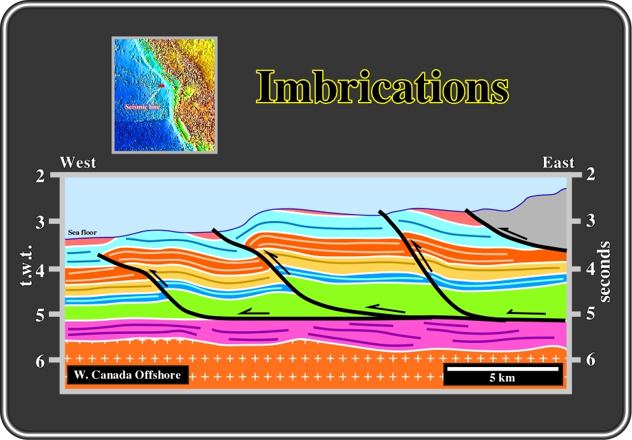
Fig. 59- In this example, volume preservation is solved by imbrications of Gorda deep-water sediments over a mobile layer. A décollement surface in which all thrust faults are located directly above the oceanic crust on the top of a mobile or over-pressure interval is evident. The décollement surface represents a tectonic disharmony, since it separates two level of deformation. Below the décollement surface, the sediments are undeformed while above it they are shortened. In the western end of the line, just one level of deformation is present. Based on this, one can hypothesize that deformation progresses westward. As depicted, such movement advancement seems to be made by (i) fault propagation folds and (ii) fault-bend folds (see later).
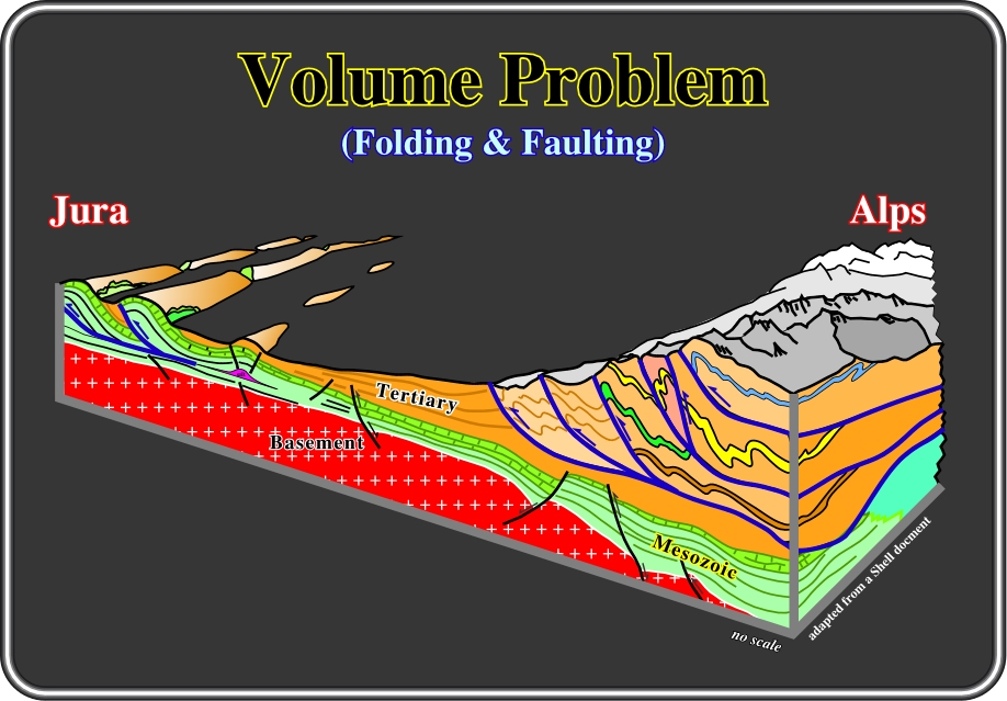
Fig. 60- This block diagram, adapted from an old Shell document, illustrates the chief ways that Nature, on the ground, and seismic interpreters, on their geological interpretation of the seismic lines, solve volume problems: (i) Folding and décollement over a mobile layers, (ii) Folding and reactivation of pre-existent normal faults, and (iii) Folding and thrusting imbrications. Indeed, following the continental collision between the Eurasia and Gondwana continents, the Mesozoic and Tertiary sediments were strongly shortened. The volume problems created by shortening were solved by different mechanisms. Thus, the sediments deposited in the Tethys Sea (Mesozoic) were accommodated to the new volume conditions by folding and faulting (with imbrications) over a mobile substratum (salt), particularly in the Jura Mountains, and by tectonic inversions within the Ampfere subduction (under the Alps). In the Alps, sediments were accommodated mainly by thrust imbrications.
b.4) Reverse Fault & Imbrigation Mechanisms
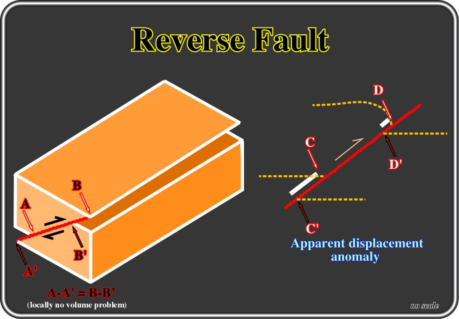
According to Anderson (1951), from the three chief types of faults: (i) Normal or Tension faults, (ii) Reverse or Thrust faults and (iii) Strike-slip or tear faults, which differ only in the varying orientation of the three principal effective stresses, only the reverse faults (or thrust faults, in conventional terminology, see De Sitter, 1964) shorten the sediments under a compressional tectonic regime. Indeed, in a reverse fault, the associated ellipsoid of effective stresses corresponds to an ellipsoid in which the maximum effective stress (
Fig. 62- On this interpretation, it is easy to see that, at the bottom of the yellow interval, the vertical throw of the reverse fault is higher than at the top. It decreases progressively upward in order to solve volume problems induced by the shortening of the sediments. A buckling of the bedding planes compensates the smaller throw on the top of the yellow layer, which does not exist on the bottom. The geometry of the lower boundary of the yellow interval is in the hangingwall. As we will see next (fig. 63), this apparent throw value anomaly can be induced by two different mechanisms: (i) folding or (ii) imbrications of the upper layers.
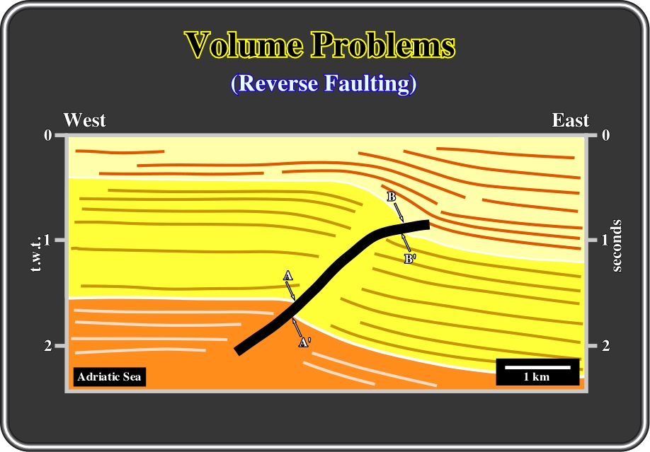
Fig. 62- On this interpretation of a seismic line from the Adriatic Sea, it is easy to see that at the bottom of the yellow interval, the vertical throw of the reverse fault is higher than at the top. In fact, it decreases progressively upward in order to solve volume problems induced by the shortening of the sediments. The smaller thrown on the top of the yellow layer is compensated by a buckling of the bedding planes (here reflectors), which does not exist on the bottom. Actually, as depicted, the geometry of the bottom boundary of the yellow interval is, in the hangingwall. As will see next (fig. 63), this apparent throw value anomaly can be induce by two different mechanism: (i) folding or (ii) imbrications of the upper layers.
In a reverse faulting, different throw displacements, along the hanginwall and decresing upward, can be caused by: (A) Folding, or buckling, of the upper part of the hangingwall (fig. 63 A) or (B) Imbrication of reverse faults (fig. 63 B). Indeed, under compressional tectonic regimes, brittle stratigraphic intervals are shortened by reverse faults. However, under certain conditions, simple reverse faulting is not enough to solve all volume problems: folding of the upper layers of the hangingwall or imbrication of reverse faults takes place in the upper layers of the hangingwall, as illustrated below.
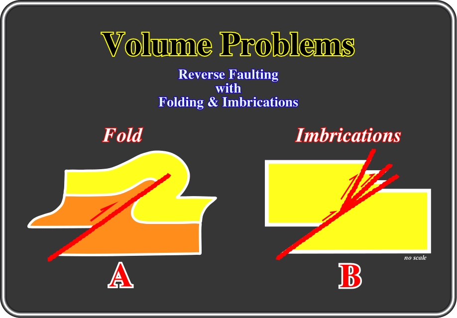
Fig. 63- As said previously, reverse faults (
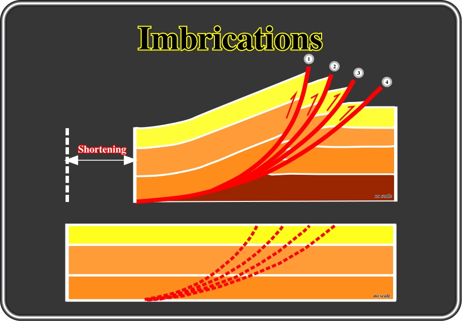
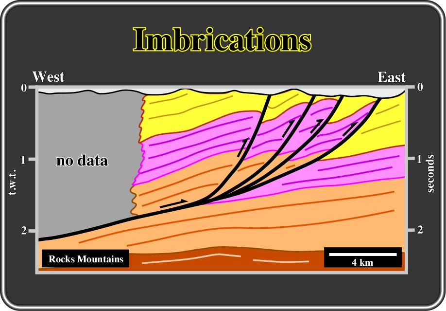
Fig. 64- On the upper sketch, sediments are shortened by imbrications of reverse faults, 1, 2, 3 and 4, in order to preserve their volume. The lower sketch corroborates the conjecture that the volume is reduced by shortening and is balanced in volume by the imbrications. However, as said formerly, the shortening movement can be in sequence or out of sequence. It is in sequence when the age of the imbrications is 1, 2, 3 and 4, and out of sequence when it is 4, 3, 2, and 1. In a sequence shortening, the oldest imbrications 1 and the youngest is 4, that is to say the shortening movement progrades forward and upward. In an out of sequence shortening, the oldest imbrication is 4 and the youngest is 1, the movement progrades backward and upward. However, it must be said that often an out of sequence shortening can be the result of the reactivation of a pre-existent basement fault. This is particularly true when the basement is not completely involved in the deformation. Generally imbrications are macroscopic structures, that is to say at the scale of the geological maps, subsequently they are more common on seismic lines (fig. 65), than on the ground.
Fig. 65- This tentative solution does not refute the conjecture that the reduced volume created by shortening is, to some extent, balanced by imbrications of reverse faults with a slight buckling in the upper part of the hangingwalls. In isolated examples, it is out of the question to conclude whether the shortening movement is in sequence or out of sequence. The regional setting strongly suggests a shortening in sequence, that is to say, that the younger faults and associated folds are the deeper ones.
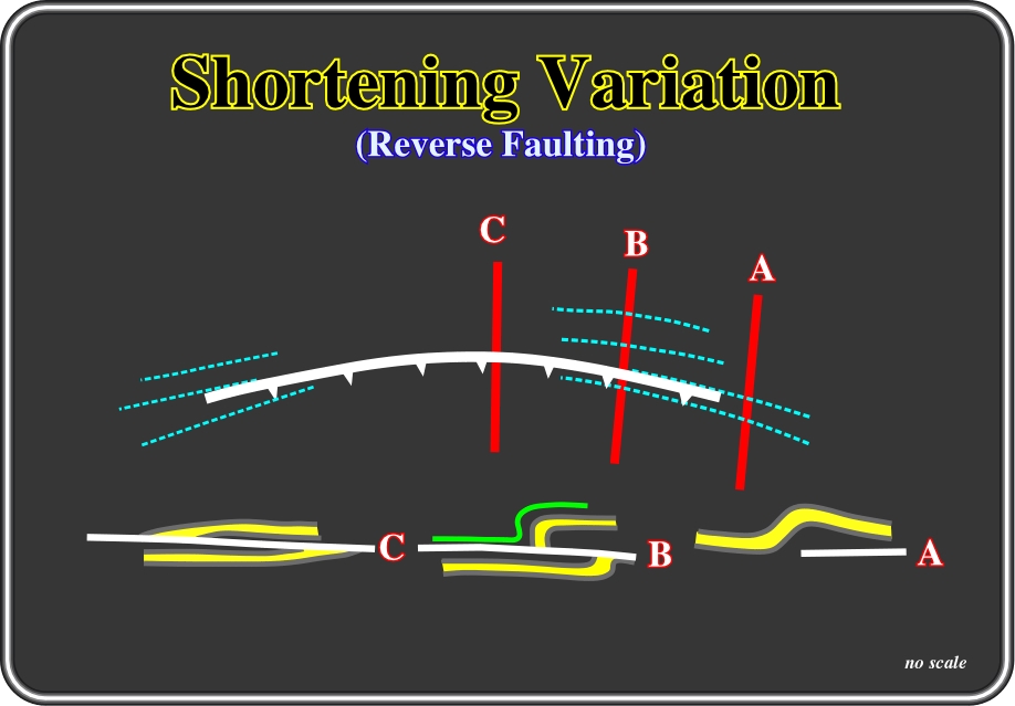
To end this subject, it is important to point out that sedimentary shortening, created by each reverse fault changes laterally. The maximum shortening is, more or less, in the middle of the fault trace, or fault line, that is to say, of the intersection of the fault plane on ground or in a reference plane, and nil at both ends. Indeed, the shortening decreases progressively from the centre of the fault line to both ends, as illustrated in fig. 66. Subsequently, a homogeneous shortening of a given area requires a system of faults, i.e., a set of contemporaneous faults (created by the same tectonic regime) connected whether in relay or by transfer zones.
Fig. 66- A long the trace of a reverse fault, shortening is maximal in the center (C). Shortening decreases toward both ends, as illustrated on this sketch before becoming nil. The geometry of reverse and thrust faults change laterally into folds, which disappear in so far as shortening becomes insignificant.
Various classifications of folds have been proposed. The majority are based on the geometry of the fold in profile section, such as the one proposed in 1984 by Van Hise, who considered two large families of folds:
(i) Parallel or concentric, in which the orthogonal thickness remains constant and
(ii) Similar, in which the folded layers have identical geometry and the thickness measured parallel to the axial plane remains constant.
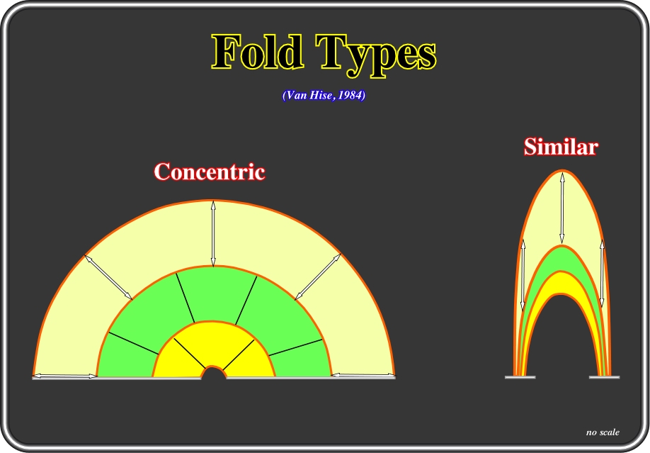
Fig. 67- Folds can be classified on the basis of several factors. Concerning the tightness of folding, the folds can be: (i) Open folds, when limbs dip gently, (ii) Tight folds, when limbs dip steeply and (iii) Isoclinal folds, when limbs are parallel. In relation to the orientation of the axial plane, the folds can be: (i) Upright folds, when the axial planes are vertical and the limbs area is symmetric, (ii) Overturned folds, when the axial axial planes are moderately inclined and one limb overturned, or (iii) Recumbent folds, when the axial planes are near horizontal and one limb inverted. Taking into account the thickness of folded bed, that is to say, on the Van Hise classification, folds can be subdivided into: (i) Concentric or parallel, when with the bed thickness is constant when measured perpendicularly to the bedding surfaces, and (ii) Similar, when the vertical distance between top and bottom of the each bed is preserved through the deformation.
According to Ramsay, J., (1976), it is possible to express the changes in shape within a fold and to classify the folded layer using any of the following parameters:
(a) Orthogonal thickness t,
(b) Thickness parallel to the axial surface T;
(c) The inclination to the dip isogons (lines on the profile section joining points on a fold of equal dip value).
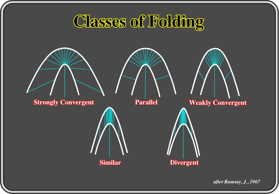
Indeed, in any folded layer the rates of change of the inclination of adjacent surfaces may vary in a number of ways, providing that the maximum curvature occurs at the hinge and that the curvature reaches a zero value at the points of inflection on the folded surfaces. Fundamentally, based on the comparison of curvature changes on adjacent surfaces in the folded layer, there are five types of folds (Fig. 68):
(i) Strongly convergent,
(ii) Parallel,
(iii) Weakly convergent,
(iv) Similar and
(v) Divergent.
Fig. 68- The chief types of fold classes are illustrated above: (i) Strongly convergent, (ii) Parallel, (ii) Weakly convergent, (iv) Similar and (v) Divergent. Dip isogons (in green) have been drawn at 10° intervals from the lower to the upper surfaces.
Although fold geometries can usually be adequately described using the dip isogon classification in conjunction with terms that describe the attitude and inter-limb angle, there are certain fold profile geometries that occur so frequently in nature that they are given specific names. These include similar folds, parallel folds, kink folds (or kink-bands), box folds and chevron folds (fig. 69).
![]()
Fig. 69- These sketches illustrated the profile geometry of a chevron fold (A), a reverse kink-band (B), a normal kink-band (C) and a box fold (D), in which the dotted lines are the traces of the hinge surfaces in the profile section.
A variety of processes other than buckling (folding that occurs in response to end-loading of competent layers) have been proposed to account for the formation of natural folds (fig. 70). Two of the most important are:
(i) Passive folding and
(ii) Bending.
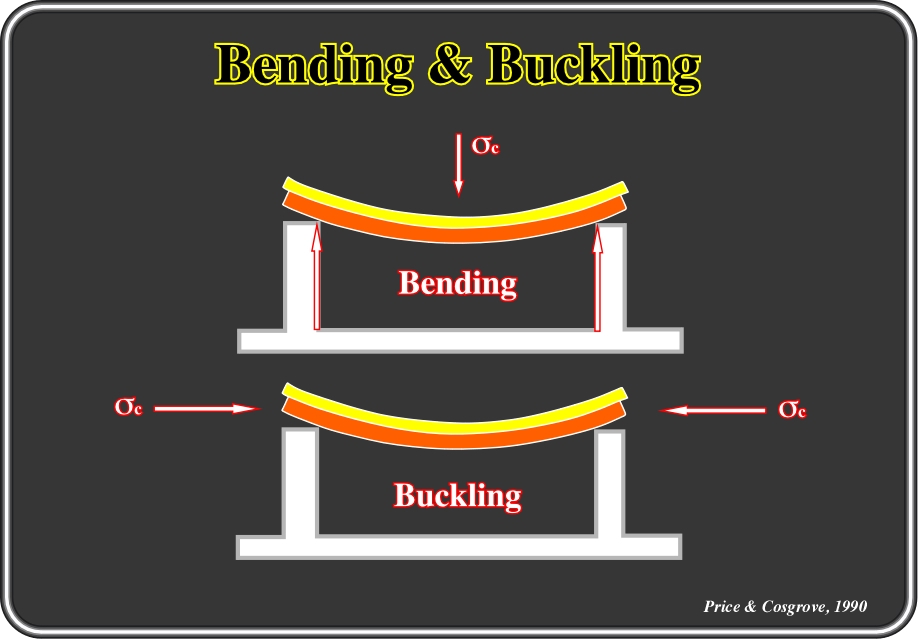
Fig. 70- These sketches depict the orientations of the principal compressions and the main difference between buckling (folding occurring in response to end-loading of competent layers) and bending (folding occurring in response to a vertical bending movement).
(i) Passive Folding
A viscous geologic body with an original sinusoidal shape, when subjected to a uniform and constant stress, after a certain time, is deformed in such a way that the dimensions of the deformed block is given by the amplification of original undeformed shape. The rate of amplification of the folds in such a passive marker increases exponentially with time. This deformation is purely a kinematic effect and is not a true instability in the mechanical sense. Such amplification of a fold is termed kinematic (or passive) to distinguish it from the dynamic (or active) amplification of a fold, which occurs in a buckling layer. The process of folding by passive amplification will, therefore, usually be more important in high-grade rather than low-grade metamorphic environments.
![]()
Send E-mail to ccramez@compuserve.com or cramez@ufp.pt with questions or comments about this short-course.
Copyright © 2000 CCramez
Last modification:
Agosto 27, 2006