
Porto, Portugal
Contents:

10.1- Raft Tectonics
10.2- Rafts and Pre-rafts
10.3- Formation of Rafts
10.4- Back-raft and Fore-raft Structures
10.5- Raft and pre-Raft Domains
10.6- 1st and 2nd order Rafting
10.7- Creation of Lateral Space for Rafting
10.8- Translation Extensional Structures
         A) Singled Buried Step
         B)  Two Emergent Steps
         C) Two Emergent Steps with Salt Diapir
         D) Two Emergent Steps with Salt Diapir
10.9- Rafting and Petroleum System
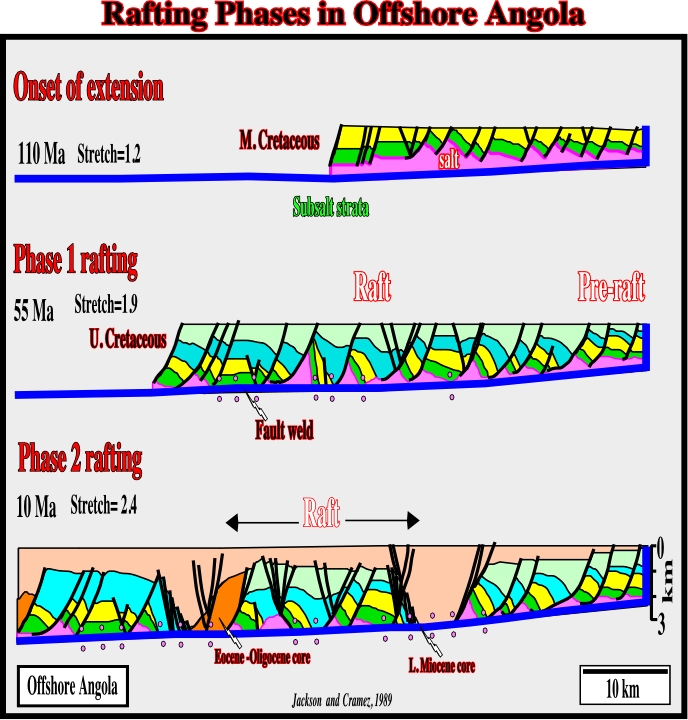
When extreme extension takes place, the overburden is broken by the opening of deep syndepositional grabens separated by intervening overburden, or rafts. The overburden slides downslope on a décollement of thin salt, like a block-glide landslide. The décollement faults may commonly be cryptic salt welds if all the salt is removed (fig. 255 and 258). Extreme type of extension known as “raft tectonics” (Tectonique en Radeaux) characterizes the offshore Angola and Gabon, as well as the eastern offshore Brazil (fig. 255 to 257):
a) Competent isopachous units broken into raft like blocks by basinward-verging normal faults.
b) Each block glides downslope on a thin salt décollement.
c) After a large amount of extension, the younger sediments can eventually lie discordantly on the salt or on its infrastructure, whereas the normally intervening competent strata area absent.
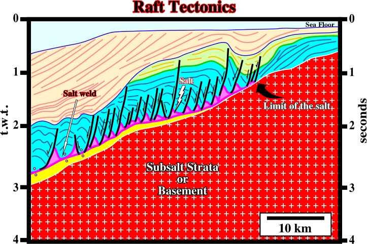
Fig. 255- In the northern part of the offshore Kwanza, southward of the Ambriz structural high, the eastward limit of the salt basin is easily located by the first major basinward growth fault and the associated Upper Cretaceous / Tertiary depocenter. Seaward, raft tectonics, induced by a seaward extension and halokinesis, is paramount. Details of this particular tectonics are illustrated in next figures.
d) This disconformity coincides with thin salt layer, but it is primarily a detachment surface. Therefore, it is rather a décollement fault rather than a salt weld.
e) If the salt layer is thick enough, raft tectonics can be accompanied by salt diapirism.
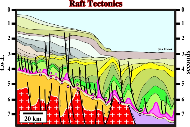
Fig. 256- Raft tectonics is quit frequent in offshore Brazil, particularly in Campos and Santos basins. On this line (Campos basin), the tectonic disharmony associated with the bottom of the salt is quite visible, with more or less developed salt and fault welds. Due to the horizontal scale, in the western part, the rafts are not too evident. On the contrary, down-dip, the rafts are more evident, as well as, huge antiform structures created by salt tectonics.
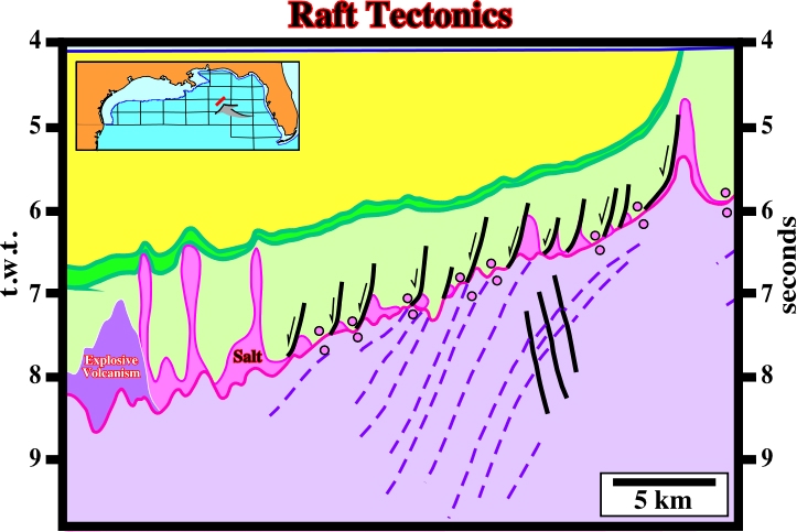
Fig. 257- Rafts tectonics is also present in Gulf of Mexico, particularly near the Florida escarpment, as illustrated on this seismic line. Indeed, immediately overlying the sub-aerial volcanism (SDRs and delta lavas), rafts of the overburden are easily recognized. Seaward of the rafts, salt diapirs are developed. They should not be confused with the explosive volcanism, which can be recognized on the left end of the line. The southwestern limit of the Jurassic salt basin seems to correspond roughly to the explosive volcanism (dark purple).
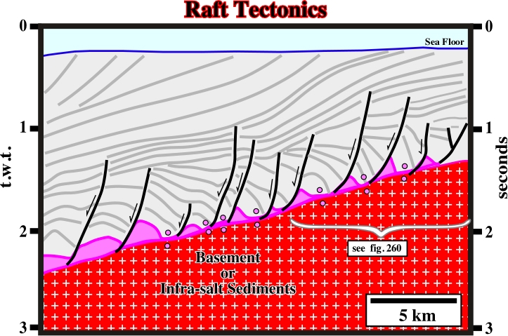
Fig. 258- Above the tectonic disharmony, induced by salt flowage, raft tectonics is paramount. An isopachous sedimentary layer, which originally was overlying the salt, was broken into different blocks (rafts) by listric normal-faults with a seaward vergence. The seaward gliding of the rafts created space available for deposition of the synkinematic layers, which by progressive gliding developed apparent downlap surfaces. The eastern part of the line is zoomed in fig. 257. It shows all rafts’ details.
Rafts are faulted blocks of allochthonous overburden that have separated so that they do no longer rest on their original footwall (the adjoining fault block) and lie on a décollement layer, which typically consist of salt or a salt weld (fig. 259).
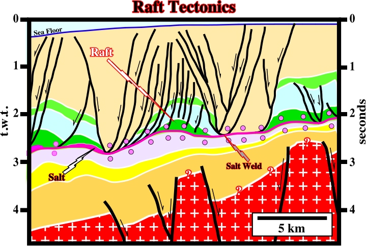
Fig. 259- The rafts of the overburden are here completely separated from the original adjoining faulted blocks. Also, the original thick salt layer is reduced to a salt weld.
Generally, the length of the raft exceeds its thickness. On the other hand, rafts may comprise both prekinematic and synkinematic strata and may themselves consist of smaller, older rafts, which became yoked together by later sedimentation before being rupture again, to move as a single large raft (see later, 2sd order rafting). Rafts are separated by trough-like depocenters of younger synkinematic strata. Pre-rafts are faults blocks of the allochthonous overburden that are not completely disconnected. The down-thrown block still is resting on the up-thrown block (fig. 260).
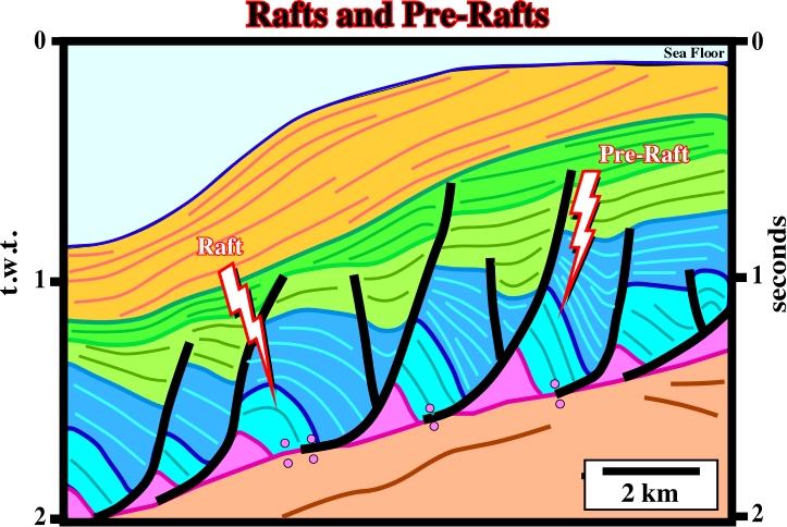
Fig. 260- On this close-up (see fig. 258), rafts and pre-rafts can be recognized. Rafts do not rest on their original up-thrown blocks. Rafts, which are not completely disconnected, are often called pre-rafts.
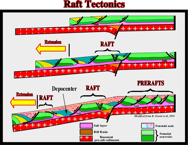
The formation of rafts is depicted in fig. 261. It can be summarized as follows:
a) An isopachous overburden overlies a thin salt. Both are slightly tilted.
c) The salt and the overburden are lengthened by normal-faults with onset of synkinematic trough-like depocenters.
d) The internal configuration of the depocenters is generally landward divergent. The chronostratigraphic lines thicken toward the normal-faults (growth-faults).
d) The down-thrown blocks of prekinematic (isopachous) interval of the overburden glide down-dip, increasing the size of the synkinematic depocenter.
e) With increasing of the fault heaves, the sedimentary lengthening reaches a point where the blocks of isopachous overburden become rafts by complete disconnection.
f) The blocks begin to be disconnected. The hanging-walls do not rest anymore on their original footwalls.
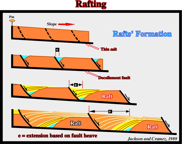
Fig. 261- In the formation of rafts, several steps can be considered. During first step, there is overburden deposition over a relatively thin salt layer. During the second step, there is a seaward tilting of the basin. In the third step, the overburden breaks in several blocks (growth-faults) and each block glides down-dip along a décollement surface (generally a fault weld) with development of synkinematic through-like depocenter. Finally, after a certain amount of extension, each block of the overburden becomes disconnect of the original footwall as illustrated in fig. 262.
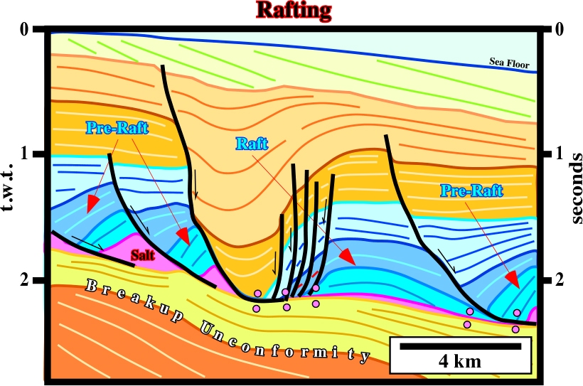
Fig. 262- The geometry of the post breakup sub-salt strata contrasts with the geometry of the overburden. The tectonic disharmony is enhanced by apparent reflections terminations, mainly apparent downlap. The prekinematic layer is broken, but some of them still are connected, while other are disconnected. In the overburden, a relatively large trough-like depocenter separates a raft structure from pre-raft structures. The original salt layer is reduced to small salt rollers and very thin salt layer or welds.
10.4- Back-Raft and Fore-Raft Structures
In offshore Angola, the similarity between the pre and post-salt structural patterns suggests that the infrastructure, that is to say, the sub-salt strata, is often implicated in the deformation. In other words, in certain cases, raft tectonics seems to be related and not totally independent of the basement tectonics (basement involvement). In offshore Angola, a careful study of the top salt horizon and of the infrastructure (tilted sub-salt blocks and basement) provides valuable information regarding the Lower Cretaceous post salt structures (fault pattern and potential traps). On seismic data, the identification of the main flanks of basement tilted blocks, fossilized by the thicker sediments filling the rift-type basins, leads to a better assessment of the (i) different shelf depositional edges, during post salt deposition, (ii) location of the potential traps, (iii) high energy environments and (iv) amount of gliding (fig. 263).

On the other hand, the conventional classification of the post-salt structures (Pinda structures, in offshore Angola) in raft and pre-rafts was revised. Total’s explorationists considered that the conventional correlation between the connected or disconnected character of the structures and the amount of extension proposed previously, was somehow biased. The top reservoir level was often located at different locations on the raft. On the other hand, using new or reprocessed seismic data, they reckoned much smaller displacements (less extension) of the structures, particularly in the proximal offshore areas. A new classification of the post-salt structures was proposed taking into account the geometric characteristics of the structures and their strong correlation with the residual topography of the basement (or infrastructure). Therefore, in addition to raft and pre-raft structures, described previously, two other types of structures were distinguished (fig. 264 and 265):
(A) Fore-rafts and
(B) Back-rafts
(A) Fore-Rafts
These structures are deposited above the upper compartments of the major basement faults and quite close to the noses of the large tilted basement blocks (see fig. 263 taking into account the translation). Some seismic examples of this type of structures are shown in fig. 264. They are supposed to present the highest hydrocarbon exploration potential. Additional characteristics features are:
(i) Presence of erosional surfaces.
(ii) Steep dips.
(iii) Large salt pillows.
(iv) Deformation at Lower Tertiary level.
(B) Back-Rafts
Back-rafts are another type of post-salt structure (fig. 265). They are deposited just above the downward compartment of the major faulted blocks (see fig. 263). Therefore, they are presumed to have the highest exploration risks (high accommodation, low energy). These risks are related to:
- The misinterpretation of the top reservoir level.
- The possible presence of a waste zone.
- The possible decreasing of the porosity induced whether by a large water depth or by anhydrite plugging.
A complication of this rather simple classification can be introduced by the structural pattern of the infrastructure, which often shows different structural trends. Indeed, in the offshore of South Atlantic margins, and particular in offshore Angola, the presence and the reactivation of the old fracture zones of the basement, which strike more or less NE-SW, enhances the complexity of the structural pattern. However, fracture zones are easily recognized on the seismic data. They generally displace the bottom of the salt layer (or weld) and they can create compressional structures in the overburden, when reactivated.
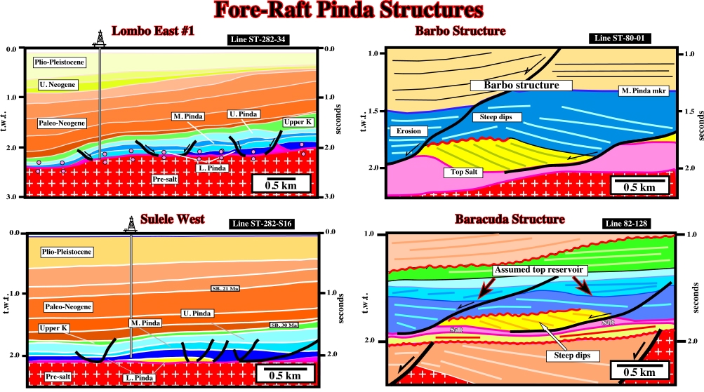
Fig. 264- As illustrated above, fore-raft structures have two main geometries: (i) an antiform geometry, as in Lombo East #1 and Sulele West, or (ii) a tilted geometry, as in Barbo and Barracuda structures. The geometry depends whether the salt below the structural high had flow away or not. In other other, the antiform fore-raft geometry corresponds to a tectonic inversion induced by salt tectonics, which does not take place in the tilted geometry. Fore-rafts show generally angular unconformities at the top of the reservoir facies.
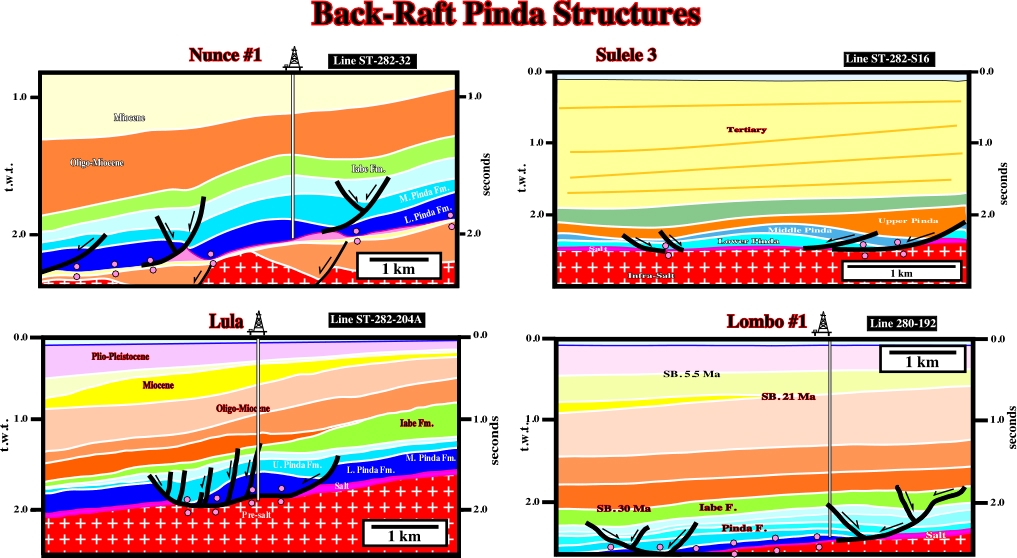
Fig. 265- All the examples of back-raft illustrated above have an antiform geometry created by salt withdrawal. The internal configuration of the different Pinda intervals is divergent landward in association with an apparent downlap seismic surface (rotated onlaps induced by compensatory subsidence). Reservoir facies are possible, but they are restricted to the seaward most part of the structures. The preponderant facies of these structures has sealing characteristics.
10.5- Raft and Pre-raft Domains
In the salt basins of the South Atlantic margins, where raft tectonics is usually present, the location of raft and pre-raft structure is not aleatoric. Indeed, as illustrated in fig. 266 and 277, a pre-raft domain is located landward of the Atlantic hinge, while the raft realm is located seaward, where the tilt of the margin is much higher.
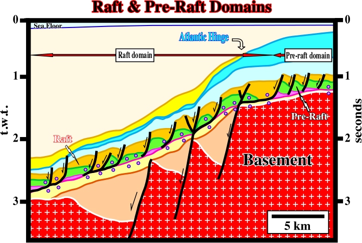
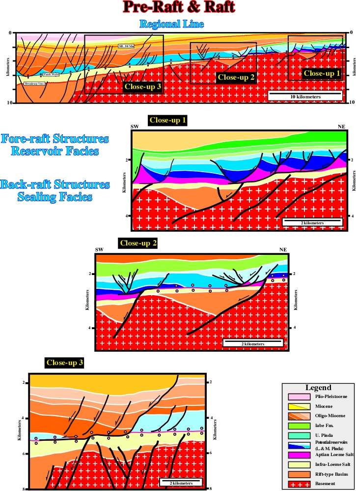
Fig. 266- Toplaps on the sea floor indicate uplift and erosion. Uplift took place during Late Tertiary enhancing the structural behavior. The Atlantic hinge is easily located. The break-up unconformity shows a sharp change in dip, as well as the tectonic disharmony. The pre-rafts are located landward of the Atlantic hinge. Seaward, the rafts are predominant.
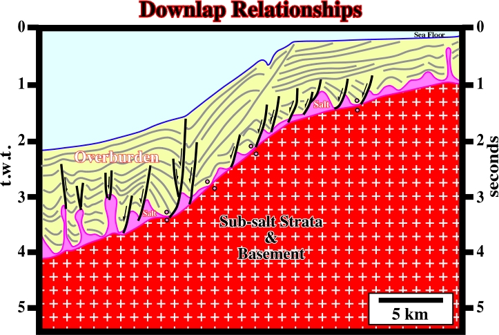
Fig. 267- Pre-raft and raft domains are also easily recognized in offshore Gabon and Gulf of Mexico (see next plates).
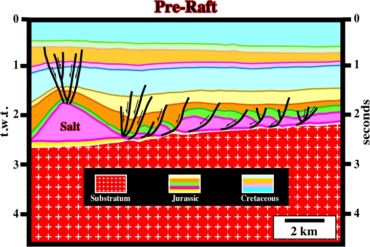
Fig. 268- On this line of the onshore Louisiana, the raft tectonics is materialized by an evident pre-raft domain. The normal-faults extending the margin do not disconnect the salt layer. In this salt basin, the tectonics is quite similar to that found in the South Atlantic margins. Only the age of the salt layer is different. Here, it is older (Jurassic). The carbonate reservoir distribution, particularly in the Smackover formation (in green) follows the same basic geological principles of halokinesis and salt tectonics.
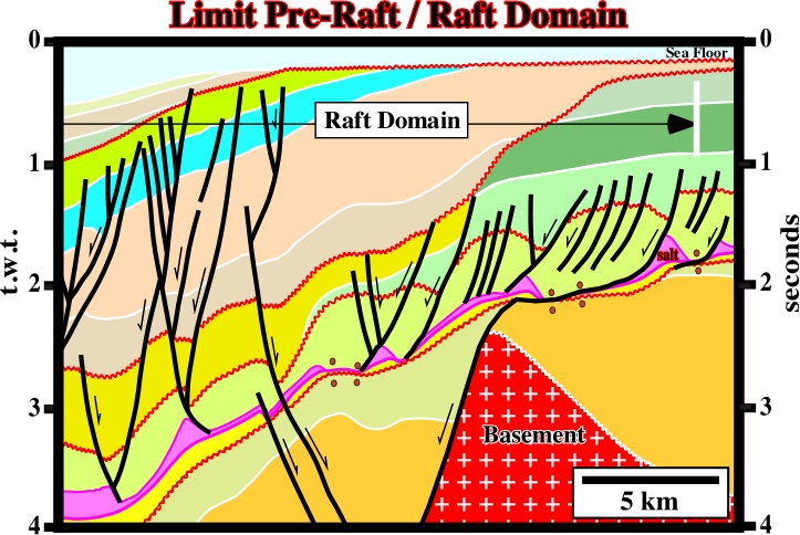
Fig. 269- The limit between the raft and pre-raft domains, in the north offshore Angola (see map in the next figure), is easily recognized on this line. It corresponds roughly to the Atlantic hinge, which is here enhanced by the Late Tertiary uplift of the margin. The geometrical relationships between the chronostratigraphic lines (seismic markers) and the sea floor are so sharp (toplap by truncation) that several geologists working in the area have advanced a 2-3 km of upheaval. Recently, the amplitude of the uplift, particularly, in the onshore, has been questioned.
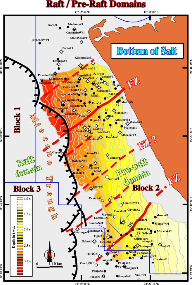
Fig. 268- On this time contour map of the bottom of the salt, in Northern offshore Angola (block 2), a complex Tertiary faulting zone limits the pre-raft from the raft domain. The orientation of the major fracture zones (in red) and their impact on this limit is quite visible. However, as illustrated in fig. 269, it must be pointed out that pre-rafts can be present in a raft domain, particularly in deep water.
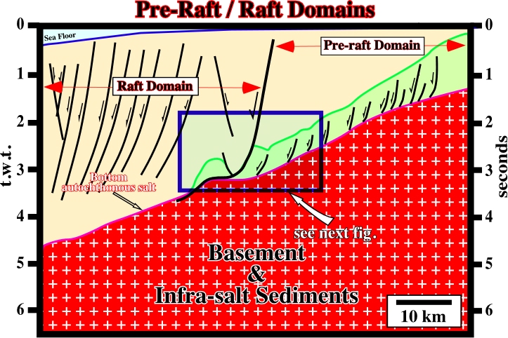
Fig. 269- In the northern conventional offshore Angola (block 2, see fig. 268), the Tertiary fault zone limiting the pre-raft and raft domains always evident on regional lines. The large raft visible on the toe of the major fault plane is illustrated in next figure.
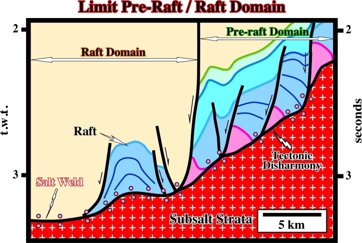
Fig. 270- Seaward of the major Tertiary fault zone (see map in fig. 268 and regional line in fig. 269), a quite large raft is well recognized at the bottom of an important through-like depocenter. As illustrated in the next line, within a raft domain, it is possible to find packages of pre-rafts. Such a feature is quite important. It refutes the “shoal model” invoked by certain explorationists to explain the reservoir intervals, particularly those in blocks 2 and 3 of the offshore Angola.
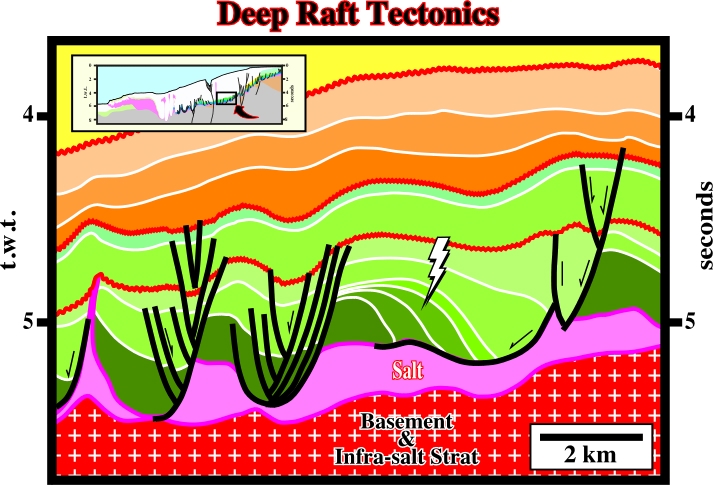
Fig. 271- In deep water, seaward of the limit between the pre-raft and raft domain (see location of the figure on the regional line, left upper corner), pre-rafts are recognized with the raft domain. A significant back-raft structure can be seen in the middle of the line. Actually, as it will be shown later, in offshore Angola, the presence of Mesozoic pre-raft domains between Tertiary rafts can be explained by rafting episodes of different ages.
The sketch below (fig. 272) summarizes the more likely mechanism for the formation of pre-rafts and rafts. Several tectonic-sedimentary phases can be considered:
a) Along a slightly dipping margin, the salt layer flows, generally down-dip, inducing the breaking of prekinematic overburden (when present) creating at the same time an shelf increasing accommodation.
b) The relative sea level rise induced by the compensatory subsidence (generated by salt flowage) increases the space available for the sediments and deposition takes place.
c) Asymmetric synkinematic depocenters thickening toward the growth fault planes, which extend seaward the overburden, are deposited.
b) Increasing of thermal subsidence reactivates pre-existent faults (pre-breakup and rifting faults) creating sharp dip changes on the bottom of the salt layer. It is the onset of the Atlantic hinge.
c) Seaward of the dip change, extension induced rafting. The isopachous faulted blocks are disconnected, while landward, they stay more or less connected. There is no welding.
d) The subsidence increases the extension. Therefore, large depocenters, lying on very thin salt or directly above the sub-salt strata, are formed seaward of the Atlantic hinge.
e) Landward of the Atlantic hinge, the extension is almost nil. The accommodation is created mainly by halokinesis (salt flowage), but, generally, it is insufficient to change the pre-raft geometry.
10.6- 1st and 2nd Order Rafting
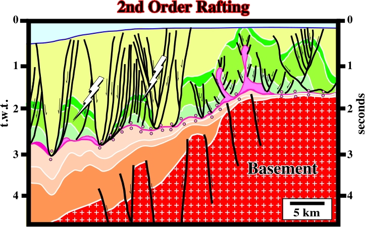
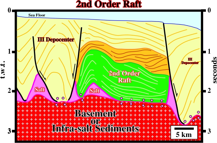
During the evolution of the South Atlantic margins, several rafting phases took place. In offshore Angola, as illustrated in fig. 274, two main rafting phases are likely. In the first phase, there was formation of pre-rafts and 1st order rafts, while 2nd order rafts were formed in a second rafting phase. Rafts can glide down-dip together inducing the formation of huge depocenters lying directly upon the sub-salt strata or infrastructure (see fig. 275 and 276).
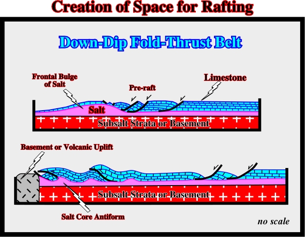
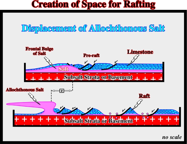
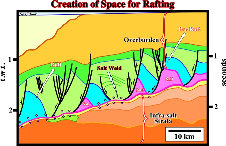
10.7- Creating Lateral Space for Rafting
Rafting tectonics needs space. Theoretically, there are two basic ways to create space in order to allow rafting. They can labeled:
A) Down-dip Thrust Fold Belt (fig. 277) and B) Displacement of Allochthonous Salt (Fig. 278).
to continue press
next
![]()
Send E-mails to ccramez@compuserve.com or cramez@ufp.pt with questions or comments about these notes.
Copyright © 2001 CCramez
Last modification:
Março 19, 2006