Porto, Portugal
Contents:
4.1-Evolution Stages
     4.1.1- Mounded Stage
     4.1.2- Dome Stage
     4.1.3- Post Dome Stage
4.2- Facies and Traps
    4.2.1- Sand-Shale Sedimentary Interval
    4.2.2- Carbonate Sedimentary Interval
Three stages of diapirism are often considered (fig. 140):
a) Mounded Stage,
b) Dome Stage and
c) Post-Dome Stage
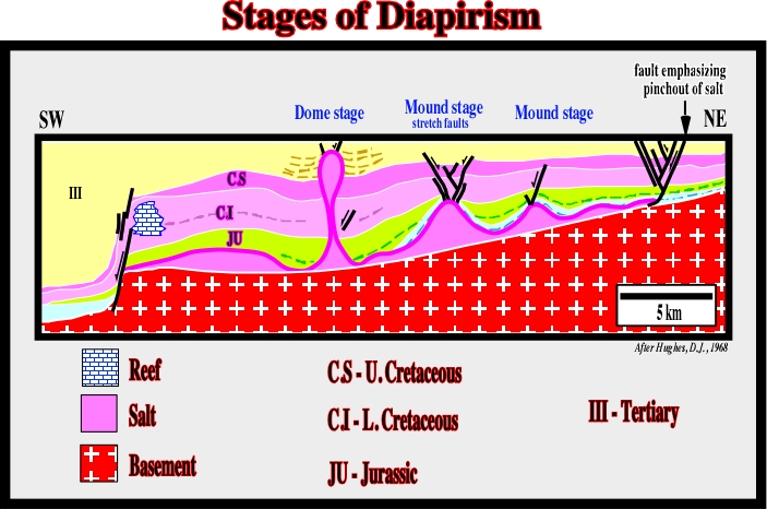
The differentiation of these different stages of a salt dome evolution is quite important. The petroleum systems and particularly the entrapment-migration petroleum sub-systems are very different from one stage to another (see at the end of this chapter). The first two stages, the mound and the dome stages, are well illustrated near the margin of the salt basins (GOM, offshore Alabama, offshore Angola, Mediterranean Sea, etc.). The post-dome stage is easily documented by the salt structures found mainly in the deep water of the salt basins.
The differential subsidence (compensatory subsidence) induced by salt flowage creates:
a) The depocenters around the mound, in which the stratigraphic intervals are thicker.
b) The uplifted area, where the subsidence is less and therefore where the stratigraphic intervals are thinner.
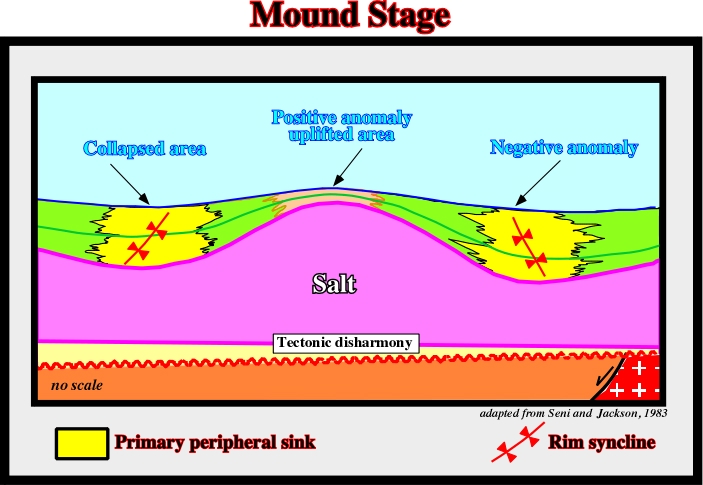
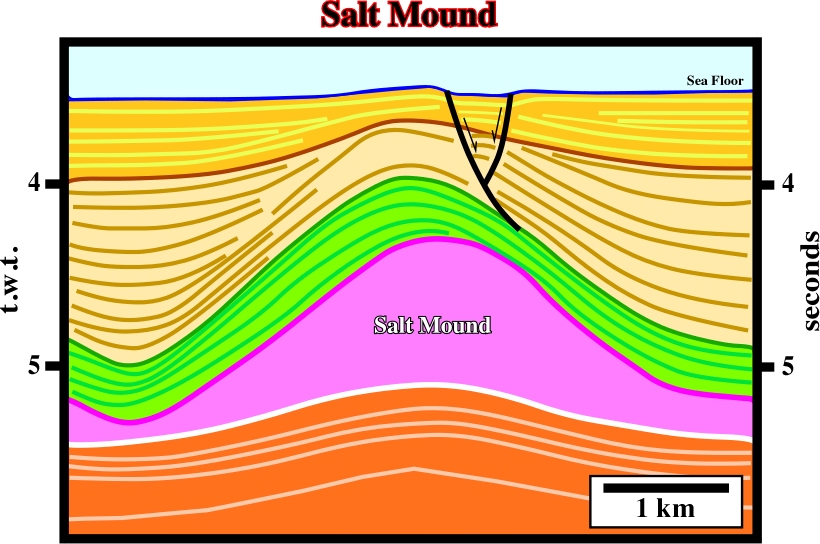
Fig. 142- The mound stage is well illustrated on this line of Mediterranean Sea, where one must take into account: (i) the tectonic disharmony at the base of the salt, (ii) the pull-up of the sub-salt strata reflectors induced by lateral changes in interval velocity, (iii) the tectonically enhanced unconformity indicating the time at which the salt started to flow upward, (iv) the onset of normal faulting in the uplift area, (v) the top of the salt is underlain by diffractions and (vi) the positive and negative topographic anomalies at the sea floor.
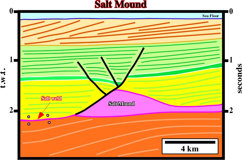
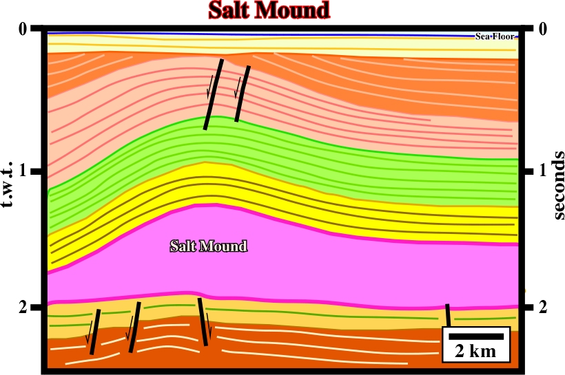
Fig. 144- This Zechstein mound seems to be created during the Cretaceous. The Cretaceous sediments show strong thickening on the western end of the line. The yellow and green intervals are prekinematic. The bottom of the Zechstein emphasizes a tectonic disharmony (décollement). The cover is decoupled from the sub-salt strata.
The continuation of the salt flowage from the flanks toward the central part of the mound, as the thickness of the overburden increases (depocenters), creates an uplift the apex of the mound forming a dome structure or diapir. The differential subsidence induced by the salt movements creates depocenters in the overburden, in which the central parts are displaced toward the dome. The apex of the dome continues to rise until the salt of the dome will be completely isolated from the mother salt layer. In such a geological situation, the flanks of the mature dome (are almost vertical. However, as said previously, due to the geostatic inversion point, such a sub-vertical geometry is mechanically unstable. With time the unstable dome geometry changes to a stable post-dome geometry.
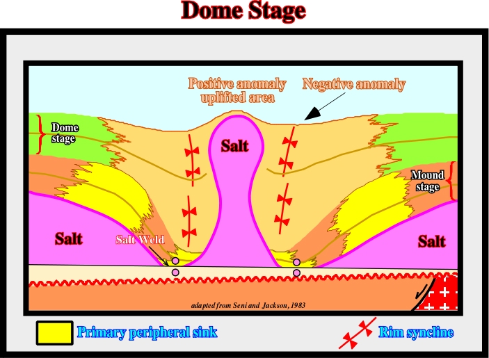
Fig. 145- When a salt structure reaches the dome stage, the structure is generally disconnected from the mother salt layer and thick overburden depocenter are developed around the dome. The depocenters developed during the mound stage are, generally located outward of those associated with the dome stage. In other words, the depocenters migrate toward the flanks of the dome.
The dome stage is often recognized on the salt structures of the North Sea. On the interpreted seismic line, illustrated in fig. 146, one can see:
a) Three salt dome structures with slightly different ages.
b) The structures (dome stage) do not seem to be disconnected from the salt mother layer.
c) Interdomal turtle-back structures.
d) Prekinematic, synkinematic and postkinematic intervals.
e) The normal-faults affecting the sub-salt strata postdate salt deposition (see later).
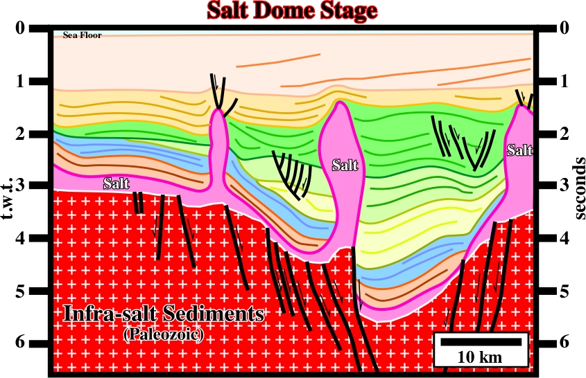
Fig. 146- In the area where this seismic line was shot, understanding the salt tectonics is paramount. The conventional petroleum system (Carboniferous / Rotlingenden) is associated with the sub-salt strata. The key parameter is the age of the traps. Indeed, the age of the sub-salt morphological traps by juxtaposition must predate the Zechstein deposition. The age of the normal-faults affecting the sub-salt strata is critical. On this line, their age appears pre-salt, but, in fact, as we will see late, they are probably post-salt.
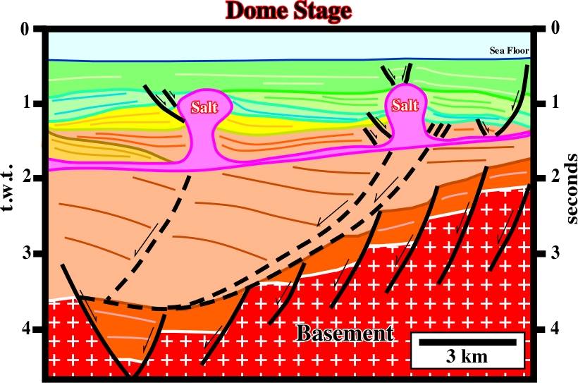
Fig. 147- Salt structures in the dome stage, with the associated overburden depocenters, are quite frequent in offshore Gabon. In this seismic line, it is interesting to notice the absence of a prekinematic interval. The salt movements started with the deposition of the overburden, or even before.
When a salt dome becomes disconnected from the mother salt layer, it cannot grow anymore. As, the nearly vertical geometry of the flank is an unstable mechanical situation:
- Below the geostatic inversion point, the lateral pressure of overburden against the salt is not balanced by the pressure the salt against the overburden. The salt of the lower part of the dome flows upward.
- Above the inversion point, the salt lateral pressure against the overburden is not compensated by the one induced by the overburden against the salt. The salt flows laterally toward the overburden creating overhang structures.
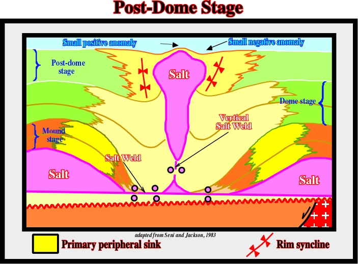
Fig. 148- The displacement of the depocenters toward the dome underlines the direction of increasing of the compensatory subsidence. Generally, in a post-dome stage, there is formation of two horizontal and one vertical salt welds. On the sea floor, a negative bathymetry anomaly surrounds a positive anomaly located just above the top of the salt structure.
- If the difference between the confinement pressures below the inversion point is big enough, the dome can be disconnected from its root creating a drop structure similar to the one illustrated on fig. 148.
- The lateral flow of the salt in the upper part of the dome creates morphological traps by juxtaposition that may be favorable petroleum exploration.
Conventionally, post-dome salt structures were interpreted as large cylindrical domes. However, interpreters (after the advent of migration processing) soon realize the space problems raised by such interpretations. The idea of using large salt cylindrical salt domes to store hydrocarbons or radioactive waste was very interesting. Unfortunately, the majority of the wells drilled, to test the salt thickness, after recognizing few hundred meters of superficial salt found again sediments (fig. 149 and 150).
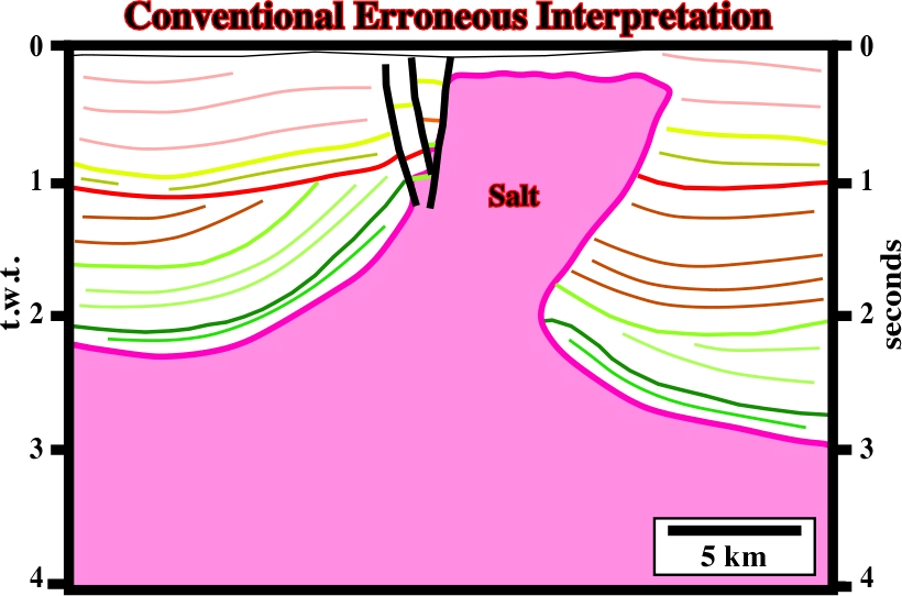
Fig. 149- This interpreted seismic line was used by a geophysical company to show the possibility of gas storage, in onshore Portugal. The partners of the project asked for a counter-interpretation (fig. 150). The results of the critical and alternative interpretation were so different that they immediately give-up the project.
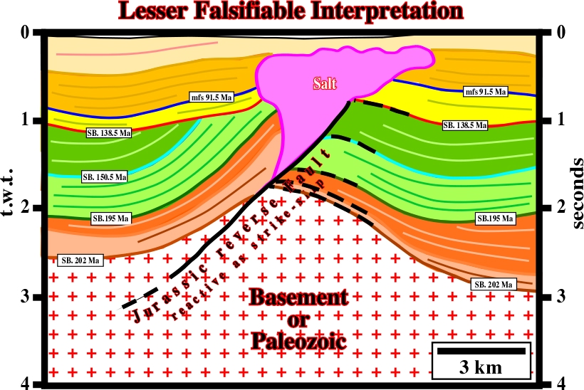
Fig.150- This alternative interpretation of the previous line takes into account the basic principles of seismic reflection, salt tectonics and rheological rock behaviors. It considers that: (i) a conventional seismic line is a two way time profile, (ii) the density of salt does not change with depth, (iii) seismic waves travel through salt at constant speed.
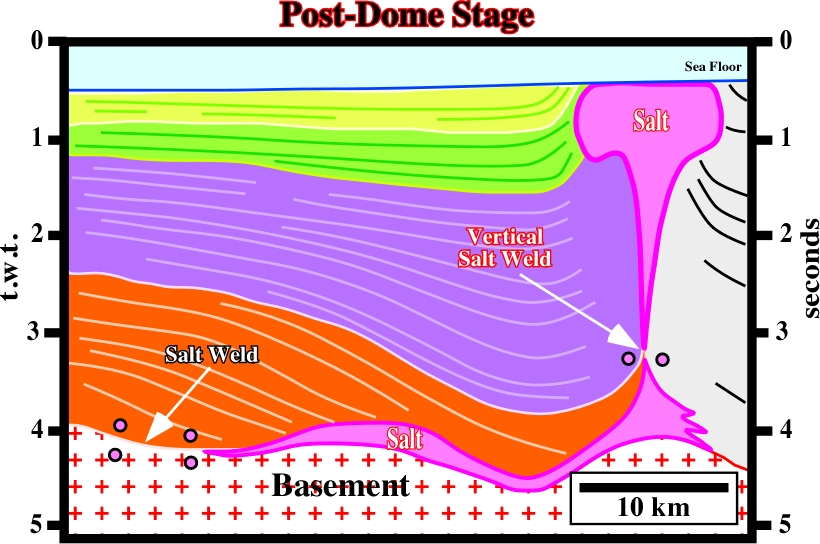
Fig. 151- In Nordkap basin, the majority of the Permo-Triassic salt structures show a post-dome geometry, which in conventional seismic lines, can only be picked using an hypothetical-deductive interpretation approach.
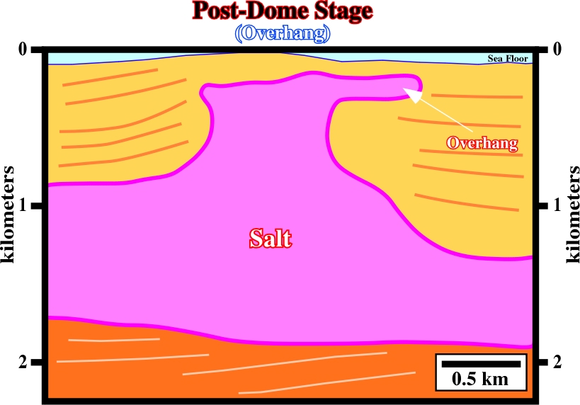
Fig. 152- The overhanging periphery of salt bulbs are characteristics of a post-dome salt stage. At the sea bottom, the positive topographic anomaly, well developed on this line, emphasizes the upward salt flowage, which contrasts with the lateral movement that creates the overhang.
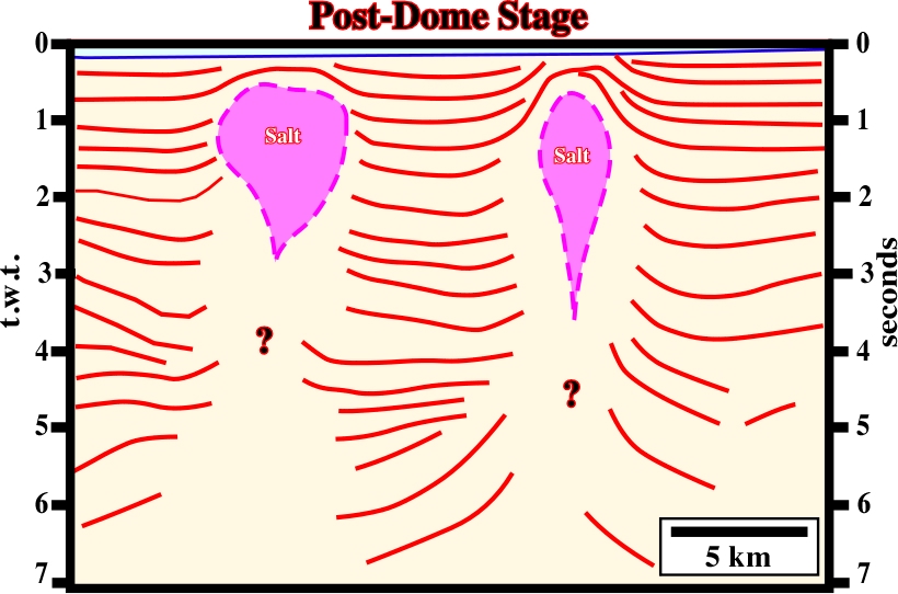
Fig. 153- In the Gulf of Mexico, detached salt stocks, or drop structures, characterize post-dome stages of salt diapirism. They can be associated with autochthonous or allochthonous salt. On this line, it is difficult to identify the salt mother layer. Two major tectonic disharmonies (décollements) can be recognized at 4.3 and 7.0 seconds.
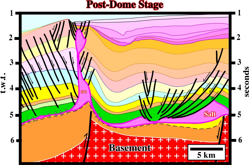
Fig. 154- At the vertical boundary of a reactivated normal-fault bordering a rift-type basin, which had reverse movement, a salt dome, with a post-dome geometry, was developed. Alternatively, such geometry can be explained as the result of local compressional tectonic regime.
In sand-shale intervals, some possible reservoir and trap distributions are depicted in fig. 155:
-The reservoirs are generally located in the areas of maximum subsidence, where accommodation, or available space for sedimentation is higher.
- The traps are mainly non-structural. They are stratigraphic or morphological.
- Structural traps (four way dips) are possible, when the apexes of the turtle-back structures, particularly those of the mound and dome stages, are not faulted. However, such a tectonic situation is rare. Turtlebacks are extensional and not compressional structures. Normal faulting lengthens the highest areas of a turtleback structure. Therefore the traps are morphological by juxtaposition (a fault-trap is a misnomer. A fault trap does not exist. A fault never traps. What can trap is a sealing rock in the other side of the fault when juxtaposed to a reservoir rock).
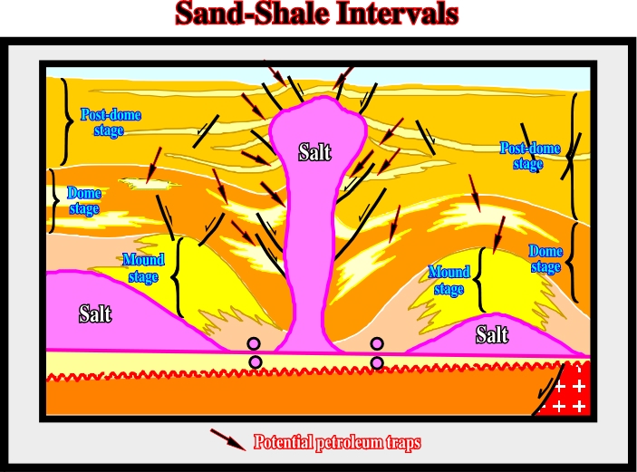
Fig. 155- This sketch illustrates the three diapiric stages of an upward salt flowage and the location of the more likely reservoir-entrapment petroleum subsystem, in a sand-shale geological setting.
In carbonate intervals, the more likely locations of the potential reservoirs and traps are quite different than those in a sand-shale interval, as illustrated in fig. 156:
-The potential carbonate reservoirs are mainly high-energy deposits, where carbonate production is greater.
-The more likely traps are non-structural:
a) Stratigraphic and morphological by juxtaposition traps (the trap classification used in these notes, and particularly the term « morphological traps by juxtaposition » clearly indicates the mapping of the sealing rock, which defines the closed area, is as important as the mapping of the reservoir. Without the map of the sealing rock, it is impossible to define a morphological trap, particularly when the morphology is related to a fault escarpment) are by far the more frequent.
b) Due to salt withdrawal, some of the stratigraphic traps are located on the flanks of structural lows (tectonic inversion). In the conventional offshore of Angola, several well-known oil fields are associated with this kind of tectonic inversion.
c) Structural traps, that is to say, traps with four way dip closure, when present (between two normal faults), are generally too small to accumulate economic amounts of hydrocarbons. The reservoirs when present are quite restricted and their petrophysical characteristics are mediocre.
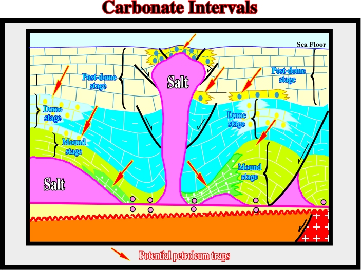
Fig. 156- When a carbonate interval is synchronous with salt flowage, the more likely location of the potential reservoirs and traps depends on the water paleo-bathymetric depth created by the compensatory subsidence. Shallow water depth induces high-energy depositional environments, in which reservoirs are likely. Therefore, the potential reservoirs are generally associated with thinner stratigraphic intervals.
In 1984 Total’s geologists proposed these kind of tectonic inversion induced by salt withdrawal to explain the structures and the reservoir facies distribution of the Pinda formation, in block 2 of offshore Angola (fig. 157). This model (raft tectonics) was proposed as an alternative to the “shoal model”, which had been systematically refuted by the exploratory wells. In salt withdrawal model, the carbonate reservoirs are mainly controlled by halokinesis. Carbonate reservoir facies are deposited over the Loeme salt structural highs. However, following salt withdrawals and lateral salt flowage, structural inversions take place and the initial structural high areas become structural lows (e.g. Lombo East#1, Tubarão#1, Sulele #1, etc.).
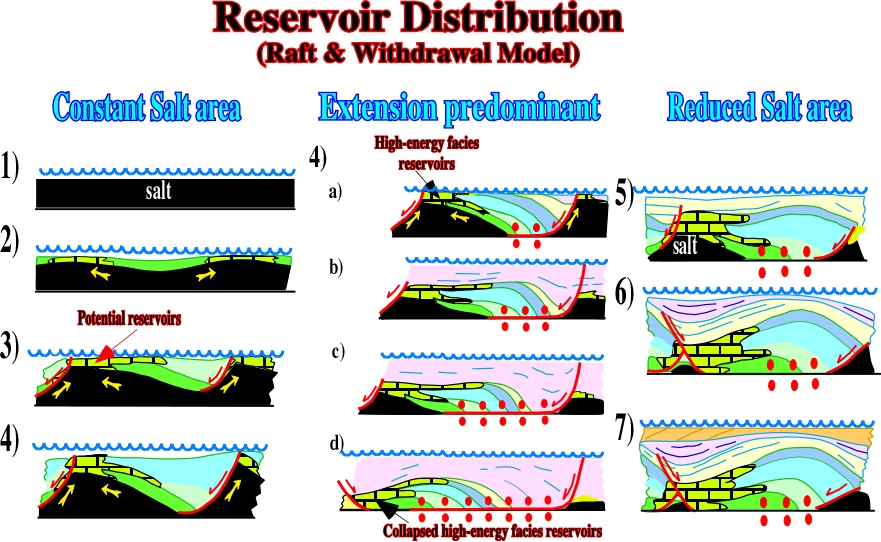
Fig. 157- Total’s geologists proposed raft-tectonics with salt withdrawal to explain structures and reservoirs facies distribution of the Pinda formation in block 2 of offshore Angola. Roughly, in the raft tectonic model, the carbonate sedimentation is mainly controlled by the halokinesis thereby the reservoir facies are deposited over the Loeme salt structural highs. However, due to salt withdrawals and lateral salt flowage, structural inversions are formed and the initial structural high areas become structural lows. The success of this salt tectonic model was mainly associated with the discoveries of Lombo East, Tubarão, Sulele, etc.. Nevertheless, since then the model could not explain all Pinda structures and reservoir distribution. It was partially refuted by new geological and geophysical observed data
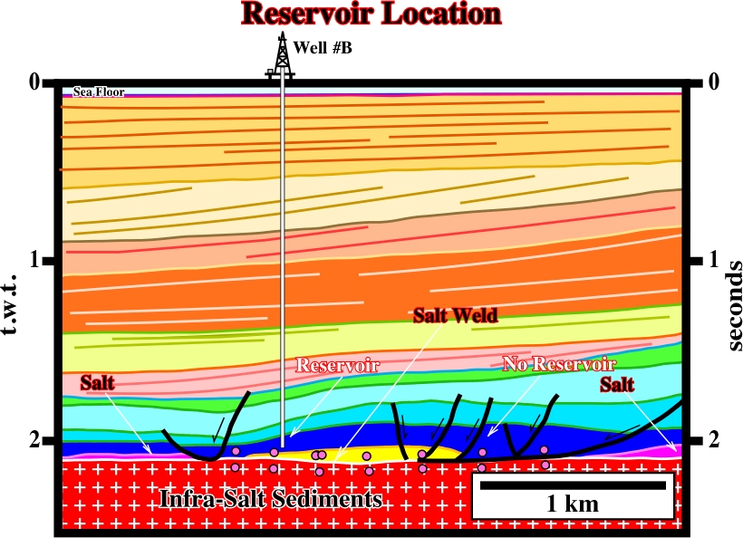
Fig. 158- The reservoir location in Sulele West follows the raft and withdrawal model depicted in fig. 157. The Middle Pinda interval progressively thins westward. Such thinning correlates with an increasing of the reservoir qualities of the high-energy carbonates. Eastward, where all Pinda intervals become thicker there are no reservoirs. Therefore, the trapping mechanism is mainly stratigraphic.
Fig. 159- Benza Quitel #1 illustrates the case of a sand-shale interval deposited during salt flowage. The reservoirs are thicker toward the NE fault, where the compensatory subsidence was higher. Again, the trapping mechanism is mainly stratigraphic. The sandstone reservoirs pinch out up-dip.
to continue press
next
![]()
Send E-mails to ccramez@compuserve.com or cramez@ufp.pt with questions or comments about these notes.
Copyright © 2001 CCramez
Last modification:
Março 19, 2006