

Millions years ago. Therefore, it expresses a geological age. Ma should not be confused with My, which means a period of time expressed in million years. Thus, SB. 30 Ma expresses the unconformity with age 30 M years ago, which is bounds a stratigraphic cycle, while 30 My expresses a period of time of 20 M years , which can be Paleozoic or Meso-Cenozoic.
Igneous rocks composed chiefly of one or more ferromagnesian, dark-colored minerals in its mode. The term igneous was proposed by Cross (1902) to replace the term femag, that is to say, a mnemonic term derived from ferric + magnesium. It is a complement of felsic.
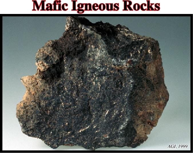
The picture above illustrates a mafic igneous rock, that in this particular case is a basalt. The term igneous was proposed by Cross (1902) to replace the mnemonic term femag.
A withdrawal basin flanking elongated salt walls without a rim.
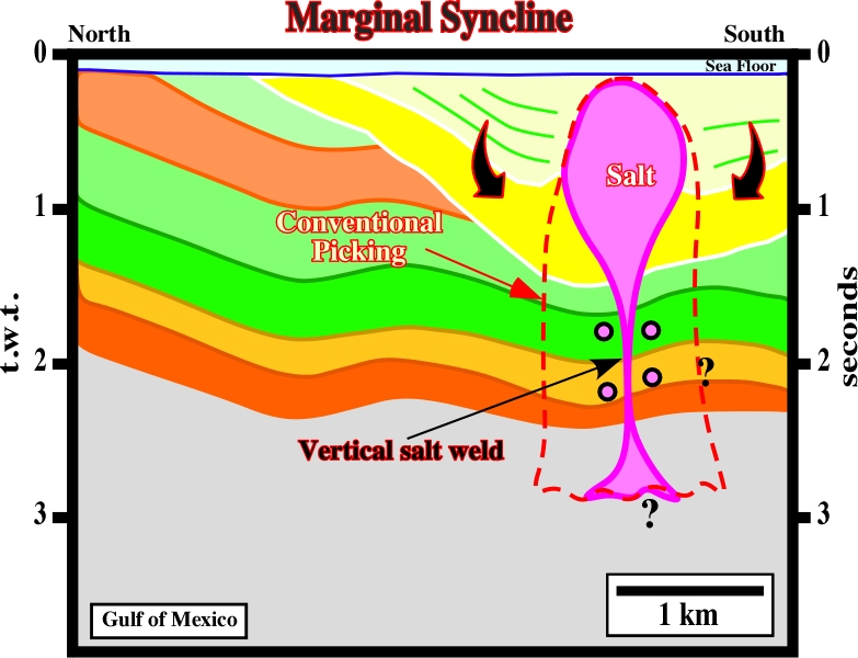
On this line, synkinematic layers form the rim synclines, in each flank of the salt dome. The prekinematic layers are isopachs. Their thickness is roughly constant. A vertical salt weld connects the salt diapir with the mother source layer.
A diapiric growth by the diapir's stem necking after the adjoining source layer has been exhausted during the formation of a tertiary peripheral sink. Because salt supply is restricted, growth is slow and the diapir can easily become buried if sedimentation continues.
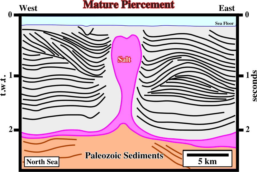
On this seismic line of South North Sea, the prekinematic and synkinematic layers of the overburden are obvious. The piercement is mature. The diapir is completely isolated from the mother source layer. Indeed, a vertical salt weld individualizes the diapir from the autochthonous salt layer. Lateral pinched-off source layers are quite evident.
The maximum axis of the effective stresses ellipsoid. It can be vertical (extension) or horizontal (compression).
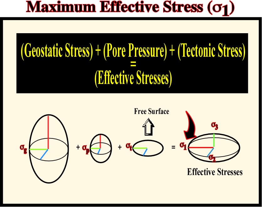
Conventionally, when the maximum effective stress, i.e.,
1 is vertical the sediments will be lengthened. When
The medium axis of the effective stresses ellipsoid. It is along of this axis that faulting and fracturing takes place.
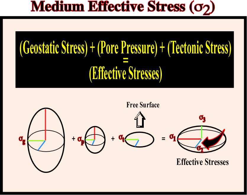
All faults strike parallel to the medium effective stress,
Earth's mobile area (folded and faulted belts) evidencing the complexity of the accretion and deformation phases undergone by geologic bodies in areas where compressional tectonic regimes are preponderant.
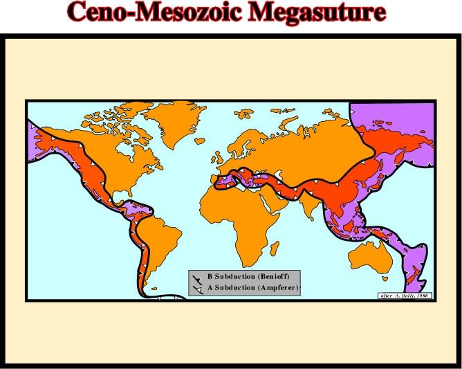
The Meso-Cenozoic Megasuture is quite easy to map. Indeed, it corresponds to the post-Pangea fold-belts. Older megasutures (Paleozoic and Precambrian) are much more difficult to map. Subtle palinpastic reconstitution are necessary.
Post Pangea continental encroachment stratigraphic cycle deposited during the younger first order Phanerozoic eustatic cycle.
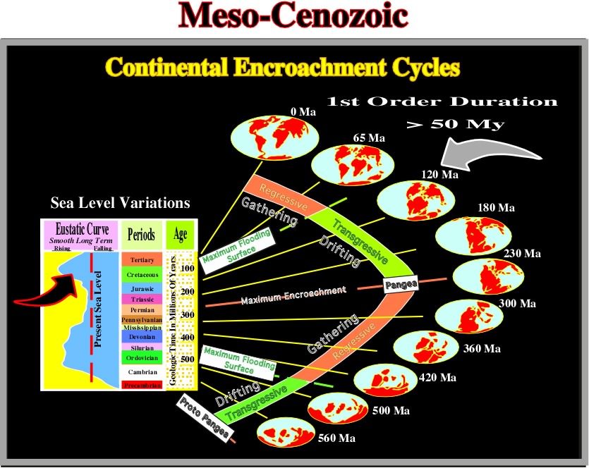
The Phanerozoic Eon is composed by three Eras (i) Paleozoic, (ii) Mesozoic and (iii) Cenozoic. The Mesozoic corresponds to the older post-Pangea eustatic cycle, while the Cenozoic corresponds to the younger post-Pangea cycle.
See: Meso-Cenozoic.
Metamorphic Rocks (McNeill, L. et al., 1999)
A group of gneiss and crystalline schists (originally used by Lyell, 1833, see below).
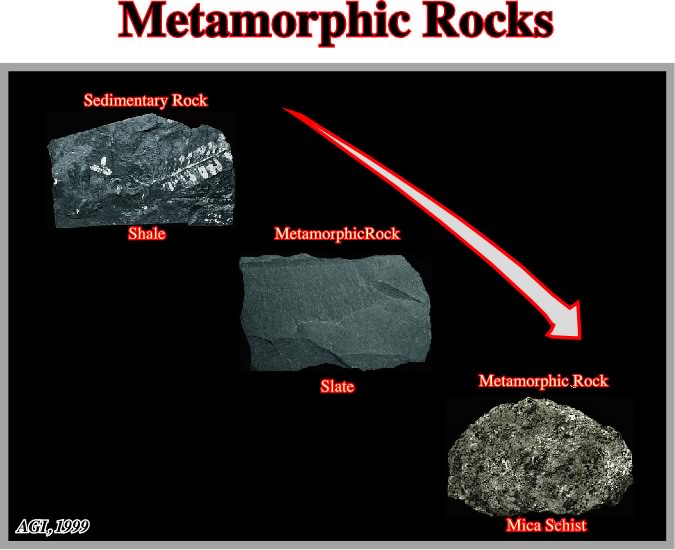
Currently, metamorphic rocks express any rock derived from pre-existing rocks by mineralogical, chemical and/or structural changes, essentially in the solid state, in response to marked changes in temperature, pressure, shearing stress, and chemical environment, generally at depth in the Earth's crust.
Synonym of Salt expulsion basin.
The minimum axis of the effective stresses ellipsoid. It is orthogonal to
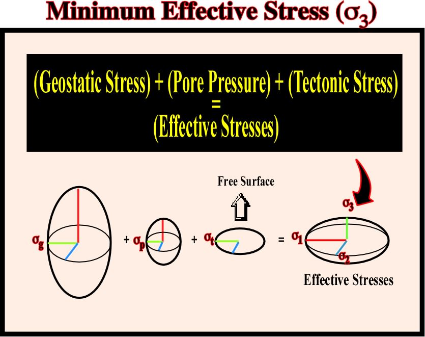
In an extensional tectonic regime, the minimum effective stress is perpendicular to the strike of the faults. The direction of the
See: Substratum.
Mohr-Coulomb Fracture Criterion
Failure during frictional plastic deformation follows the Mohr-Coulomb fracture criterion where one should take into account the shear strength, the cohesive shear strength, the normal stress, the angle of internal friction or slope of Mohr envelop and the Coulomb coefficient.
Envelope of Mohr's circles. The Mohr’s theory hypothesizes that the normal stress, in compression or tension, plays a role in the failure as well as the tangential stress. Their relationships can be determined experimentally. The graphic representation of the stresses by circles allows to determine the Mohr’s envelope. As the tri-dimensional realm of the stress can be represented in a plane and the intermediated stress does not have any influence, the Mohr’s envelope can be determined by the maximum and minimum effective stresses.
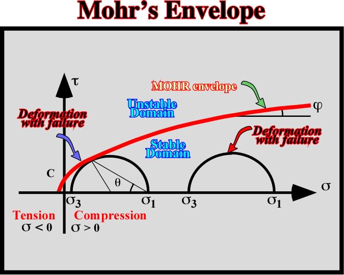
Hypothesizing that all planes, under the same normal stress failure, along the same plane containing the maximum tangential stress, the intermediate stress can be neglected. The same can be achieved by using a series of tests made under varying combinations of
Molding Models (Talbot, C. J., 1995)
A profile of the diapir entirely downbuilt in effectively. Although active diapirs must deform the overburdens they pierce, the shape of passive diapirs is formed or molded by their overburdens. The dips of salt-sediments contacts are shaped by the interaction of two processes: (i) local net accumulation of overburden (A= deposition-minus compaction) at rate Ä and the net increase relief of salt structures (R=salt rise-minus dissolution) at rate R°.
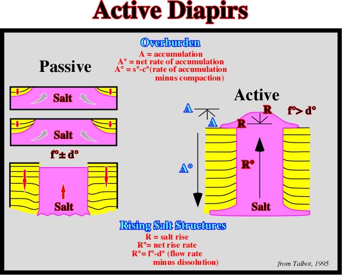
In a passive piercement, salt diapirs downbuild with crests that remain emergent as their overburden accumulates around them. In contrast to active diapirs that deform overburden already in place, the shapes of passive emergent diapirs are molded by stiff overburden. The net local accumulation, A, of effectively rigid clastic sediments occurs at rate A° (rate of aggradation minus compaction). The relief of salt diapirs, R, downbuilt by stiff overburden occurs at rate R° (flow rate of salt minus dissolution). It is assumed that both salt and sediment spread sideways as fast as they rise or accumulate respectively.
Molding Ratio (Talbot, C. J., 1995)
The kinematic ratio R°/A°, where A° is the rate of aggradation minus compaction and R° is the flow rate of salt minus dissolution.
One of the six crystal systems, characterized by either a single twofold axis of symmetry, a single plane of symmetry, or a combination of the two. Of the three nonequivalent axes, one is perpendicular to the plane formed by other two.
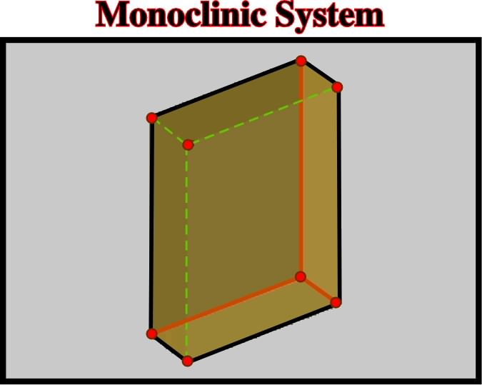
One the three nonequivalent axe is perpendicular to the plane formed by other two.
On this seismic line, the small anomalies on the top of the allochthonous salt can be considered as the initiation of a first generation salt walls or stocks.
Synonym of Source layer.
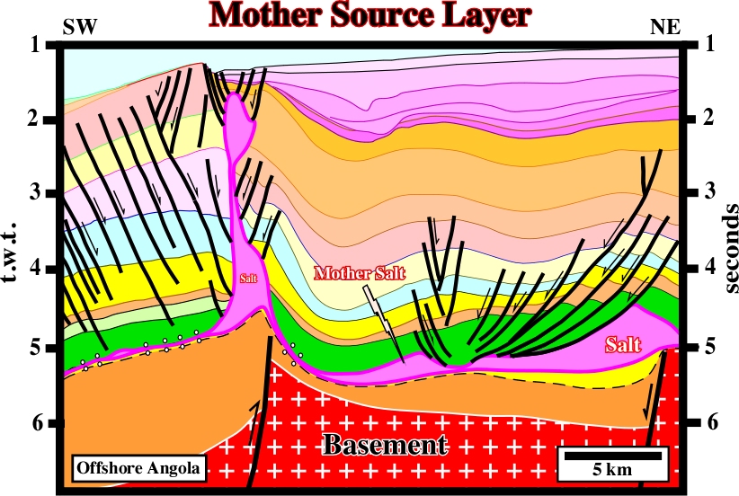
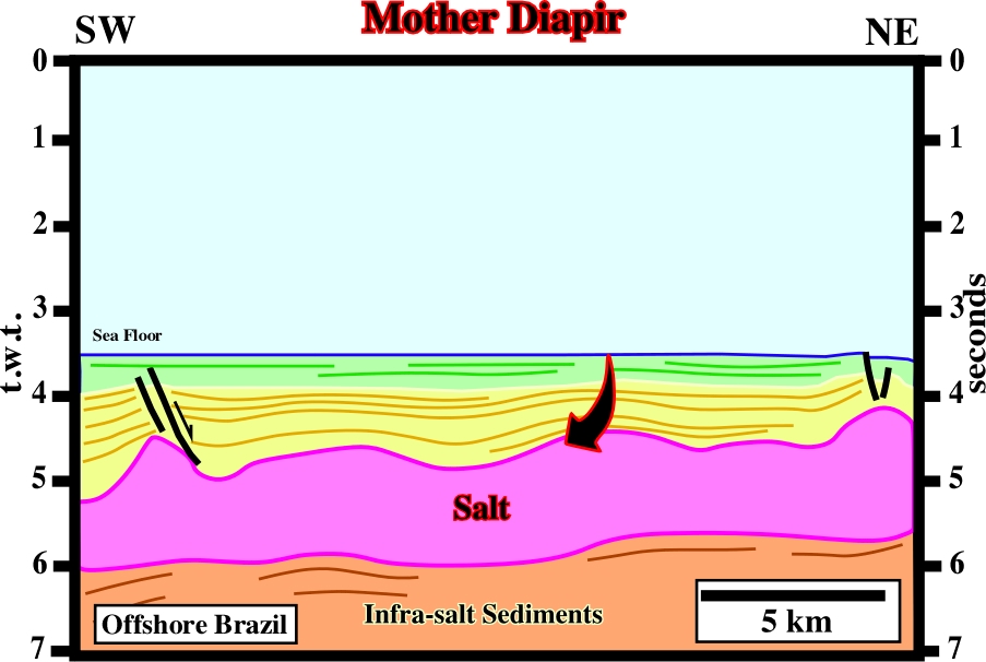
Generally, the mother source layer is easy to recognize. When it is reduced to a salt weld, the identification of the associated tectonic disharmony is necessary. When thick allochthonous salt layers are present, the recognition of the deep autochthonous salt is almost impossible even in pre-stack depth migrated data.
Differential subsidence (compensatory subsidence) induced by salt flowage creates: a) an uplifted area (mound), where the subsidence is less and therefore where the stratigraphic intervals are thinner and b) depocenters around, in which the stratigraphic intervals are thicker (see figure below).
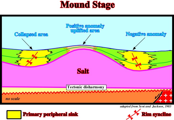
In a mound stage, the coeval overburden interval shows two depocenters on the flanks of the salt mound and relatively condensed stratigraphic section at top the mound. In this sketch, the overburden is synchronous with the salt movement.
Movement Cell (Jackson, M.P.A. and Talbot, C.J.,1991)
The volume containing closed loops of streamlines or stream surfaces in an overturning system of source layer and overburden.
Mushroom Diapir (Jackson, M. P. A., 1995)
Salt diapir having a broad bulb fringed by one or more laterally flattened, pendant skirts of deformed evaporates that envelope the stem of the diapir. Both the skirts and infolds they surround are downward-facing.
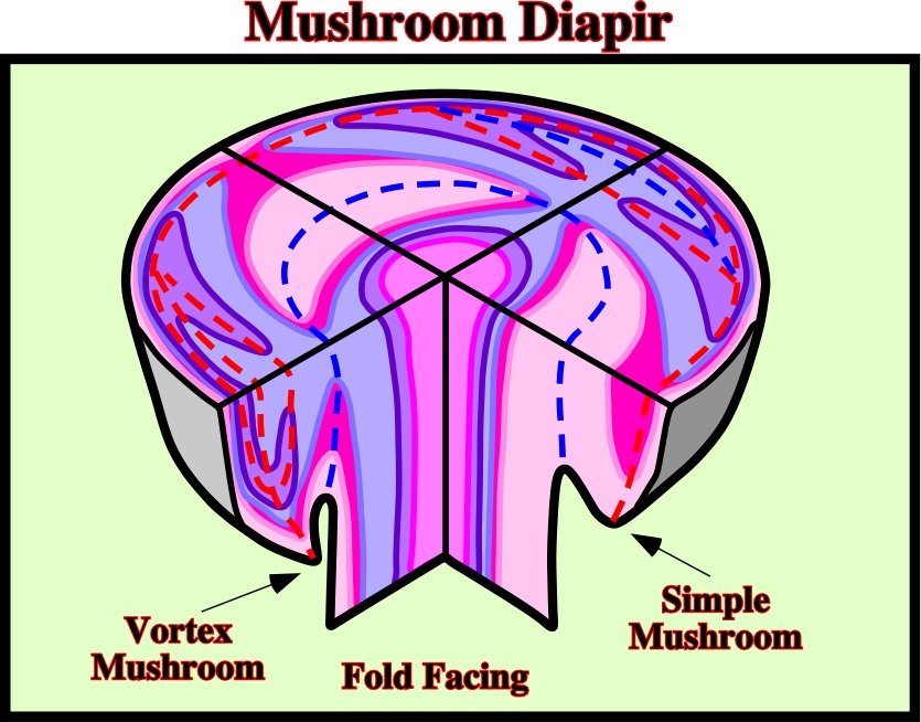
Due to its complex geometry, mushroom diapirs can be identified on the ground or with good seismic 3D data, particularly on time slice.
Mushroom Structures (Jackson, M. P. A., 1995)
The term mushroom has long been loosely applied particularly to diapirs shaped like bulbs, despite the fact that actual mushrooms are not shaped like bulbs. Truly mushroom-shaped structures have a bulb fringed by one or more pendant peripheral lobes. See: Mushroom Diapir.