
Igneous Rocks
Rocks that solidified from molten or partly molten material, i.e., from a magma.
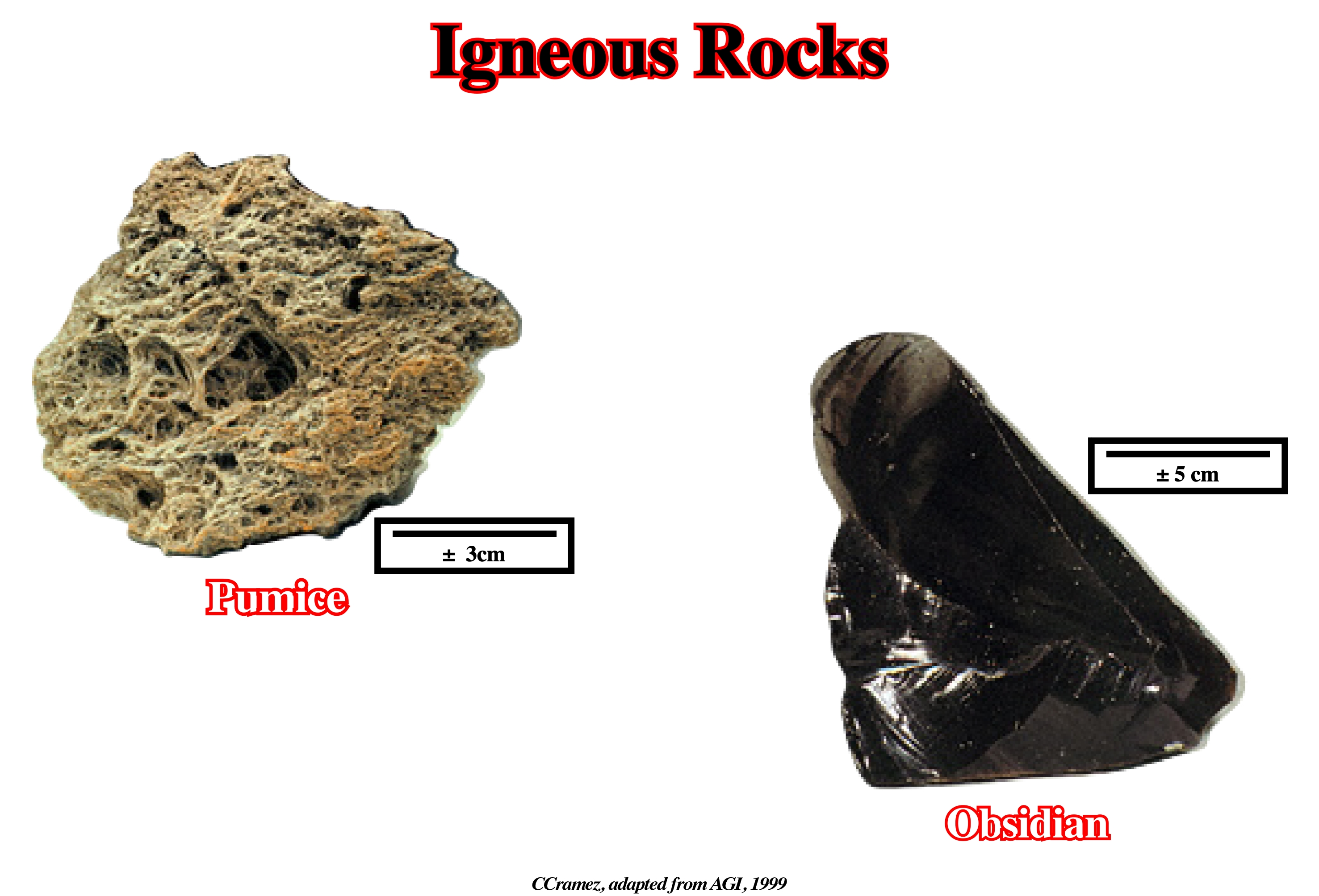
Igneous rocks constituting one of the three main classes into which rocks are divided, the others being metamorphic and sedimentary.
Inclined Simple Shear Restorations
One of the two restoration methods. There are two available methods in restoration programs: (i) Inclined simple shear and (ii) Flexural slip. The former is used in extensional fault restorations that do not retain constant bed lengths. The second is used in contractional thrust belts so that constant bed lengths are retained in constant-area deformations. Shear and flexural slip methods are used in salt restorations. Shear methods where the style is dominated by extension and salt withdrawal . Flexural slip methods where contraction is dominant.
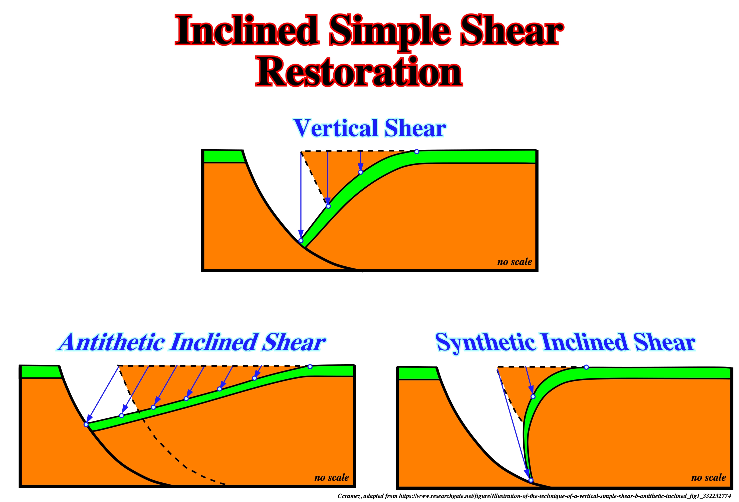
Restoring seismic, well, and outcrop data, as well as structural interpretations of growth folds. Data restorations allow viewing of seismic, well, and outcrop information in the restored state, providing a basis to evaluate whether structural interpretations are balanced and geologically reasonable. Validating structural interpretations helps to reduce the exploration risks associated with trap definition. Sequential restorations reveal folding kinematics and define the geometry of structures at various stages in geologic history (https://www.researchgate.net/ publication /279593592_Inclined-shear_restoration_of_growth_folds). Above are illustrated the three types of shear restoration in the hangingwall of a growth fault: (i) Vertical Shear ; (ii) Antithetic Inclined Shear and (iii) Synthetic Inclined Shear.
Infold
A downward-facing synform surrounded by a skirt. It is a type of crescentic fold.
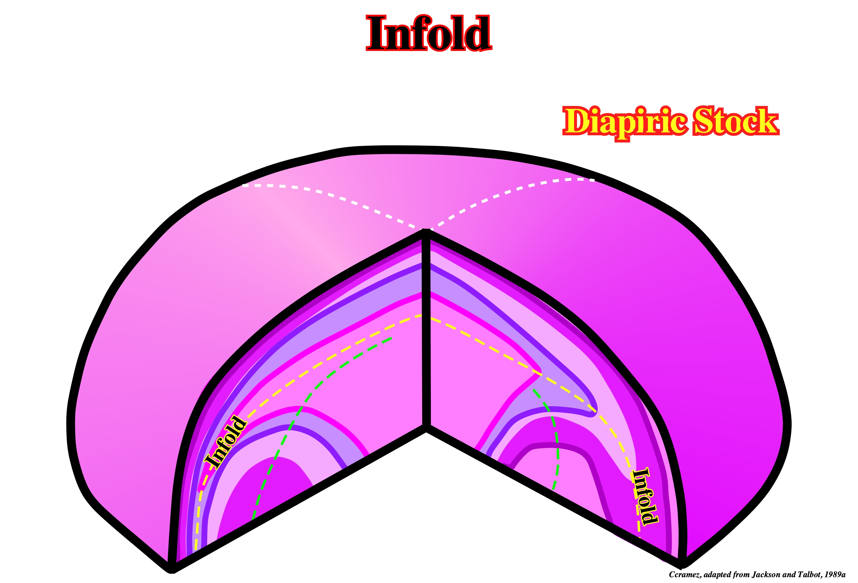
Infolds are clear seen in fluid mechanic and salt molding models. They have been recognized, mainly, in Kavir desert (Iran) and in few salt diapiric outcropping in North Africa.
Infrasalt Strata
Strata located, stratigraphically, below a significant mother salt layer or below the salt induced tectonic disharmony.
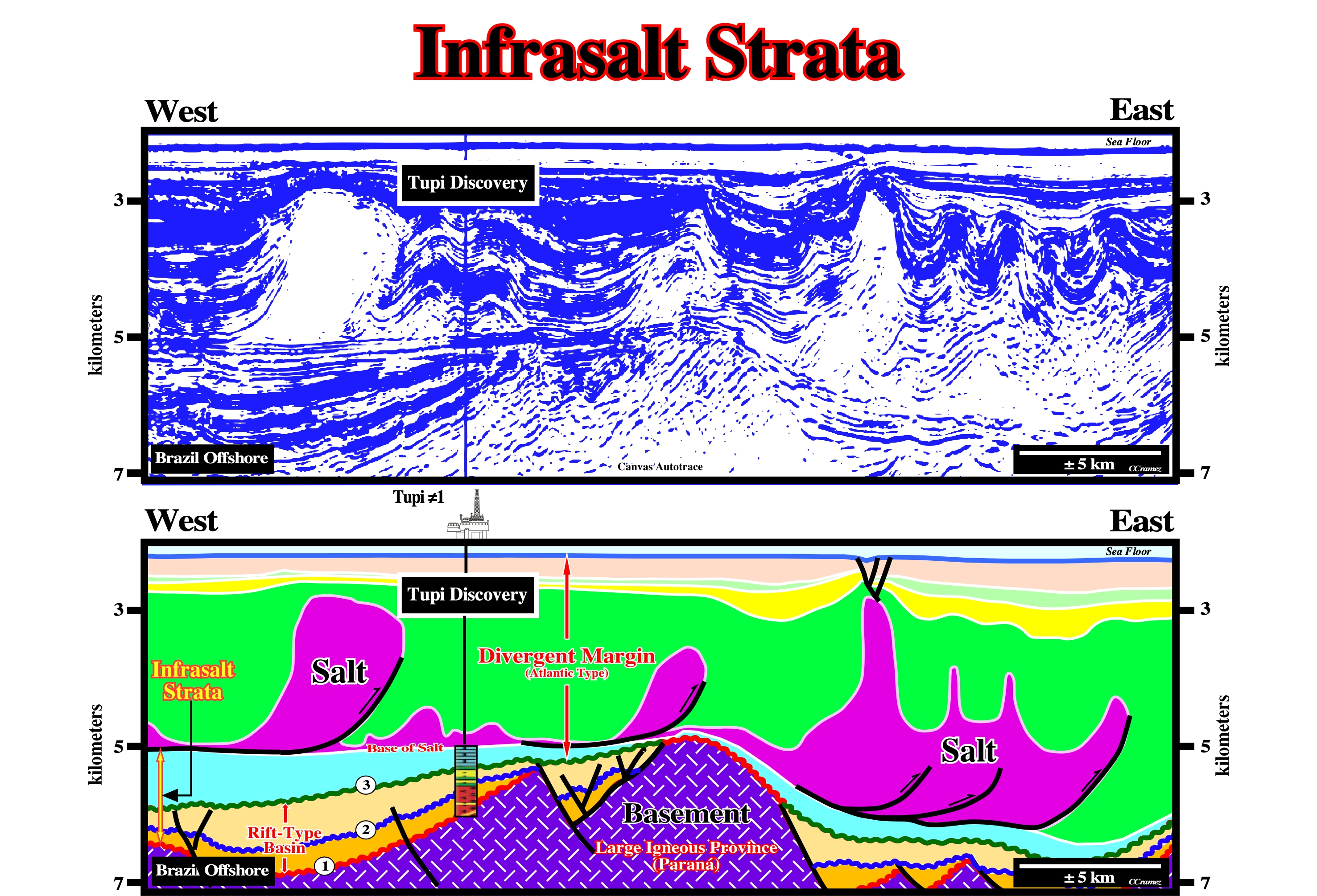
In Brazil offshore and, particularly, in the Santos geographic basin, which corresponds, in geological terms, to an Atlantic-type divergent margin overlying rift-type basin, the infrasalt strata include not only infrasalt margin sediments, but rift-type basin sediments as well. On this tentative geological interpretation of a Canvas autotrace of a Brazil offshore seismic line, the infrasalt sediments include: (i) Subsalt margins sediments (blue interval between the bottom of the salt and the breakup unconformity (unconformity n° 3), which correspond, locally, to microbial limestones with petrophysical characteristics of reservoir rocks ; (ii) Rift-type basin sediments bounded by the breakup unconformity (n°3) and the intra-rift basin unconformity (unconformity n°2), in which potential source-rocks are interbedded with coquina reservoirs rocks and (iii) The sediments bounded between the intra-rift unconformity (n° 2) and the pre-rifting unconformity (unconformity n°1), in which shales and basal clastics with talc and stevensite deposited. The basement is here composed, mainly, volcanic rocks. The subdivision in infrasalt and suprasalt strata, use by many geoscientists, has any geological meaning, particularly, stratigraphical. It corresponds just to a salt induced tectonic disharmony. Stratigraphically speaking, the infrasalt strata belong to quite different sedimentary basin individualized by the breakup of the Gondwana small supercontinent : a) An Atlantic-type divergent margin above breakup unconformity and b) Rift-type basins below the breakup unconformity. When certain petroleum geoscientists said the potential source-rocks are infrasalt, geological speaking, they are not too correct. Two generating petroleum subsystems are possible. One, in the lower part of the margin (below the salt), and the other in the rift-type basin sediments. Each of them has different characteristics and the associated petroleum systems are approached in completely different ways.
Infrastructure (in Salt Tectonics)
The subsalt strata overlying the basement.
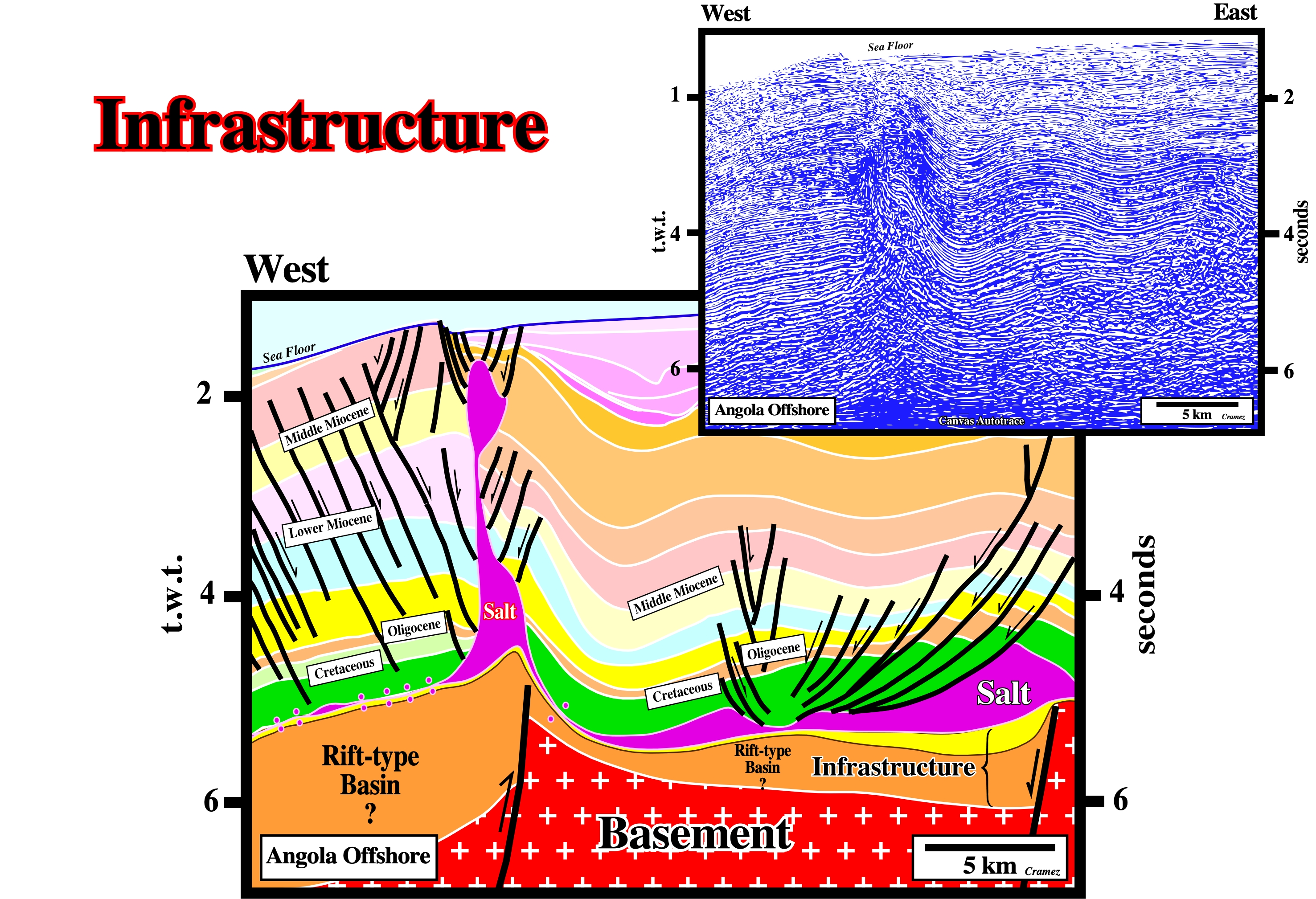
On this tentative geological interpretation of a Canvas autotrace of an Angola offshore seismic line, the infrastructure is limited between the salt and the basement. The infrastructure is, here, composed by rift-type basin sediments and the subsalt basal sediments of the margin. A major unconformity occurs within the infrastructure: the breakup unconformity.
Inharmonious Folding
Folding when the beds have different strength. Stille (1925) considered two kind of folding: (i) Harmonious, when the beds have a similar strength and (ii) Inharmonious when the beds have different strength, particularly one an high mobile layer is interbedded. The different geometries of both foldings are illustrated below.
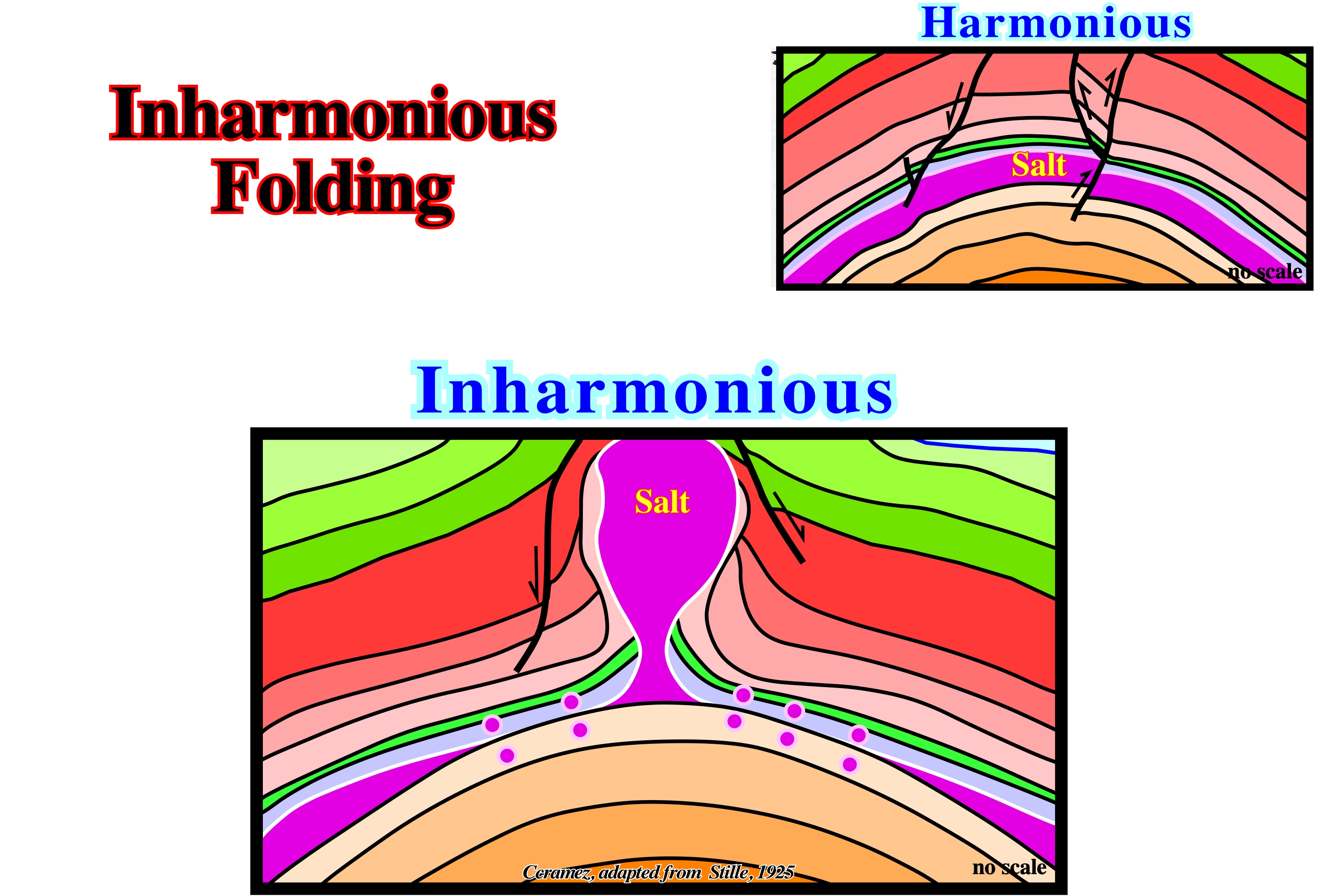
As depicted, Stille was one of the first geologists to recognize the harmonious and disharmonious folding as well as the existence of diapiric stems, verticalled pinch-off diapirs and lateral pinched-off source layers.
Injection Rate
The lateral downdip movement versus time. Salt laccoliths and salt sills are emplaced as thin sheets between strata a few meters, or less, below surface sediments. Each basal cutoff marks the advancing position of the leading edge of the spreading salt tongue at successive stratigraphic times.
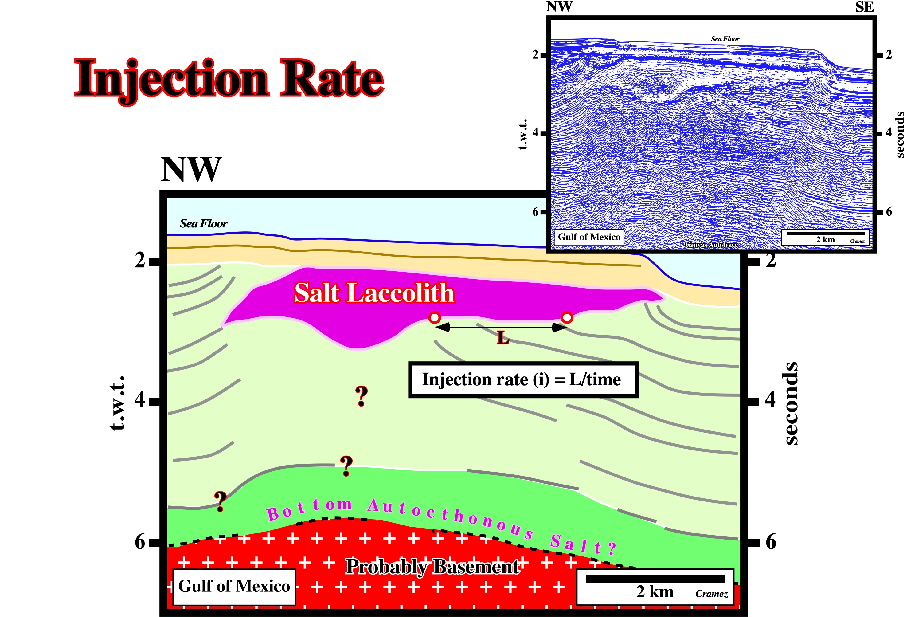
On this tentative geological interpretation of a Canvas autotrace of a GOM seismic line, the injection rate, i.e., spreading versus time, can be, roughly, assessed, since the basal cutoffs of the salt laccolith are, easily, recognized. The distance L, is, easily, measured, which is not the case of the injection time.
Interdomal Structure
See: Antiform (salt)
Internal Mushroom Structure
Structure in which skirts are contained, entirely within the diapir and thus surround antiformal, infolded synclines of evaporites.
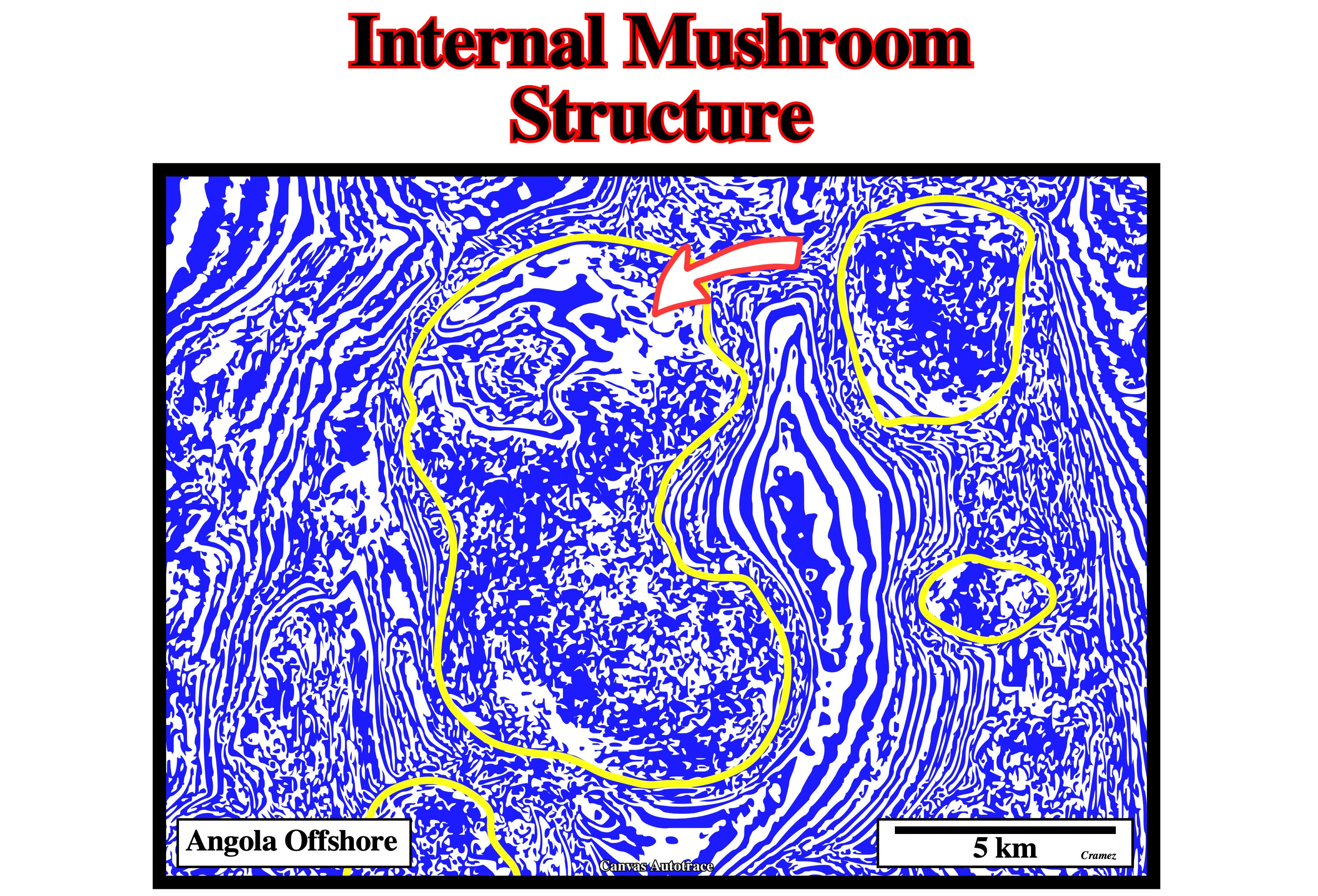
This kind of diapiric structure was recognized, mainly, on the ground in the Kavir Desert. Presently, seismic acquisition and seismic reprocessing do not allow, in the majority of the cases, to recognize them seismic lines. Time slices, performed in quite new data, allow, often, to recognize, in certain salt structures, potential internal mushroom structures, as those illustrated on this Canvas autotrace.
Internal Shear Zone
Zone within a diapir comprising only sheared evaporites. It contrasts with a boundary shear zone, which contains screens or clast trains of country rock.
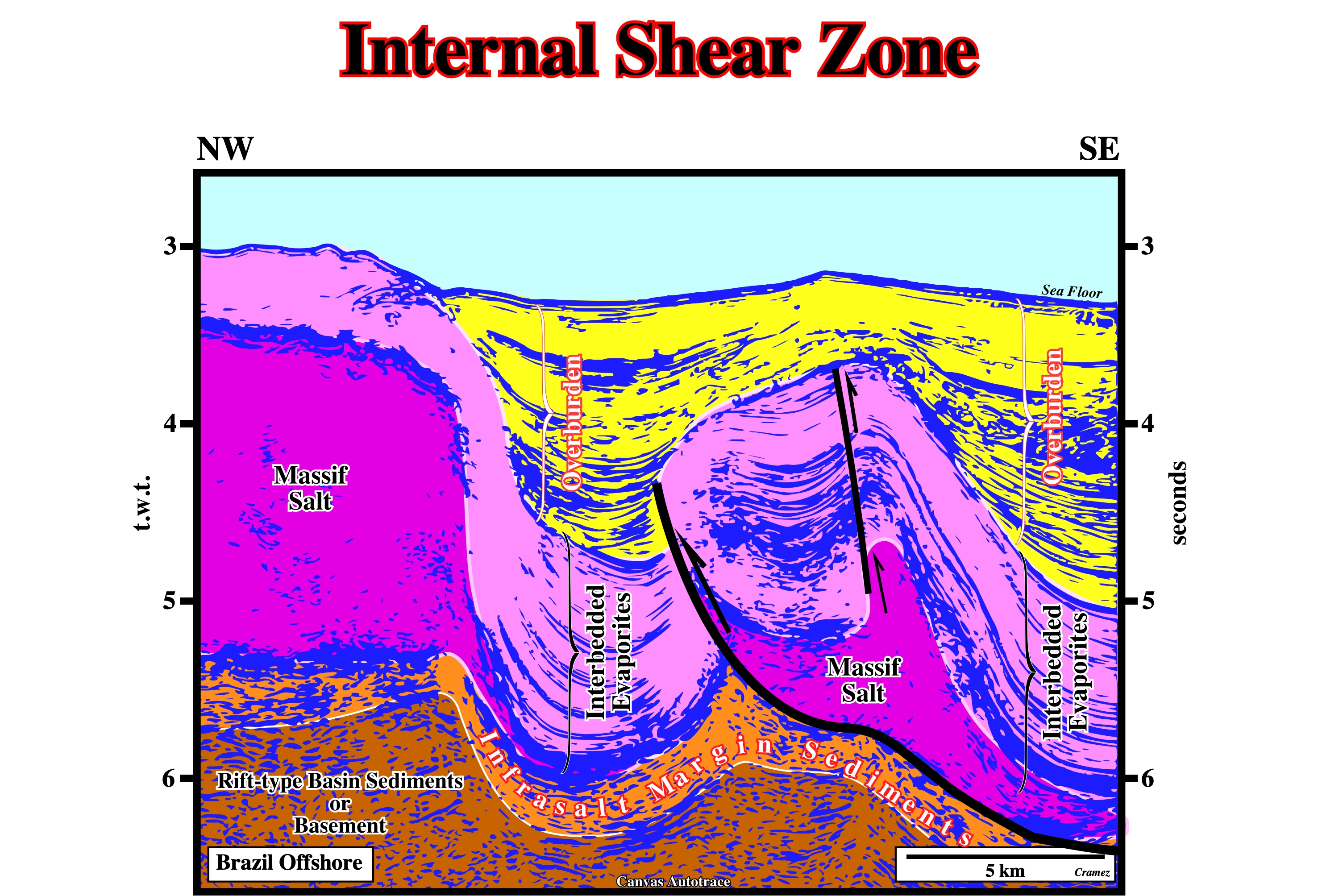
Shear zones within diapirs are difficult to observe in conventional seismic lines, particularly, in 2D Lines. In certain Atlantic-type continental margins, besides the massif salt layer, there are an interval, in which clastic sediments are interbedded with evaporites, generally, deposited above the massif salt layer. Frequent shear zones are visible in this clastic-evaporite interval, as well as in the upper part of thew massif sail, as it is the case in Brazil offshore (mainly, Santos geographic basin). At the geological point of view, the Brazil offshore corresponds to the vertical stacking of just two types of sedimentary basins (on this glossary we have used the basin classification of A. Bally and S. Snelson, 1980): Rift-type basins, which are covered by an Atlantic-type divergent margin. Locally, independently of any geological criterion, the Brazil offshore is, often, subdivided in several administrative or geographic basins, as Campos, Santos, Espirito Santos , etc. On the above tentative geological interpretation of a Canvas autotrace of seismic line shot in Santos geographic basin, the massif salt is easily recognized, as well as the interbedded clastic-evaporite interval in which shear zones can be recognized, which is not the case of the massif. Taking into account the seismic resolution and the quality of the data, their absence is not a proof of their no existence. These two levels of salt (massif salt and interbedded clastic-evaporites) are well known in Sudan offshore and North Sea (Holland offshore).
Intrasalt Basin
Synonym of salt expulsion basin or mini-basin.
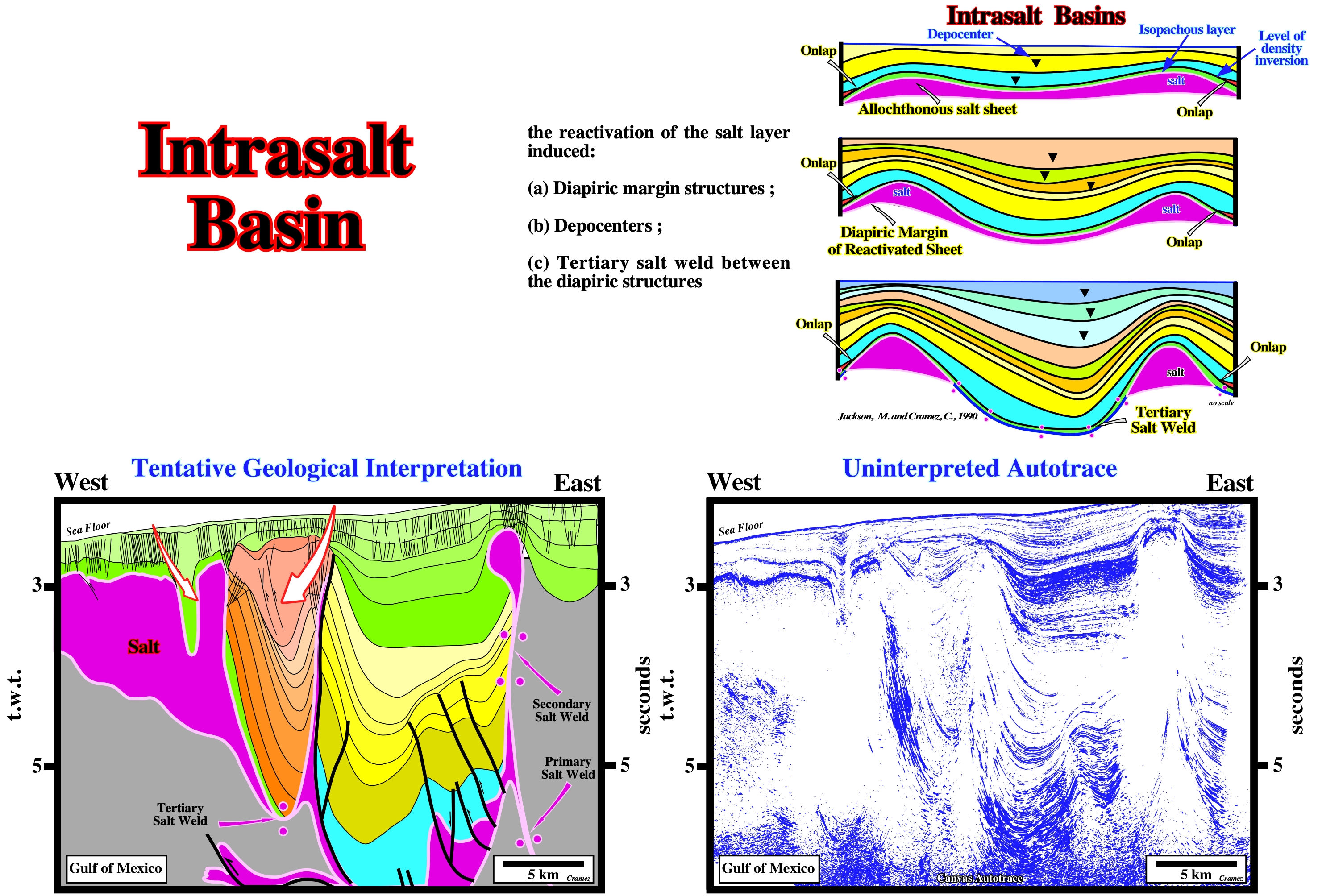
Intrasalt basin, which are often called “mini basins”, are developed over allochthonous salt. Since the salt of an allochthonous salt nappe flows down-slope, it creates a local subsidence (compensatory subsidence). This subsidence combined with eustasy creates space available for sedimentation, i.e., accommodation. Young and generally under-compacted sediments then fill the space available. These basins are, easily, recognized on seismic lines, time slices and, under certain conditions, on bathymetric maps. Salt expulsion basins are, generally, rich in reservoirs. They are, mainly, associated with turbidite depositional systems, either basin floor fans or slope fans (Vail’s terminology). The petrophysical characteristics of these reservoirs are, generally, very good. They allow high productivities in the order of 10,000-20,000 b/d, which are fundamental for the profitability of the associated accumulations, particularly when water depth is high. The geometry and continuity of turbidite reservoirs can be quite different: (i) In submarine basin floor fan (SBFF) reservoirs, generally, have large and continuous dimensions (they are often connected) and (ii) in submarine slope fan (SSF) reservoirs, in general, have small dimensions and are, rarely, connected (their discontinuity is a distinguish trait). On the above tentative geological interpretation, it is easy to see, in association with the allochthonous salt, which is connected with the autochthonous layer by a salt ramp, a large and a small salt expulsion basins. The compensatory subsidence, which created them, can only by explained by salt flowage. The bottom of the small basin is, clearly, the allochthonous salt. A salt weld can occur at the bottom of the large mini-basin, what means that hydrocarbons can, eventually, through it. Chronostratigraphic correlations between seismic intervals within and outside mini-basins are quite difficult in absence of well calibrations.
Intrusive Diapirism
Synonym of active piercement or upbuilding.
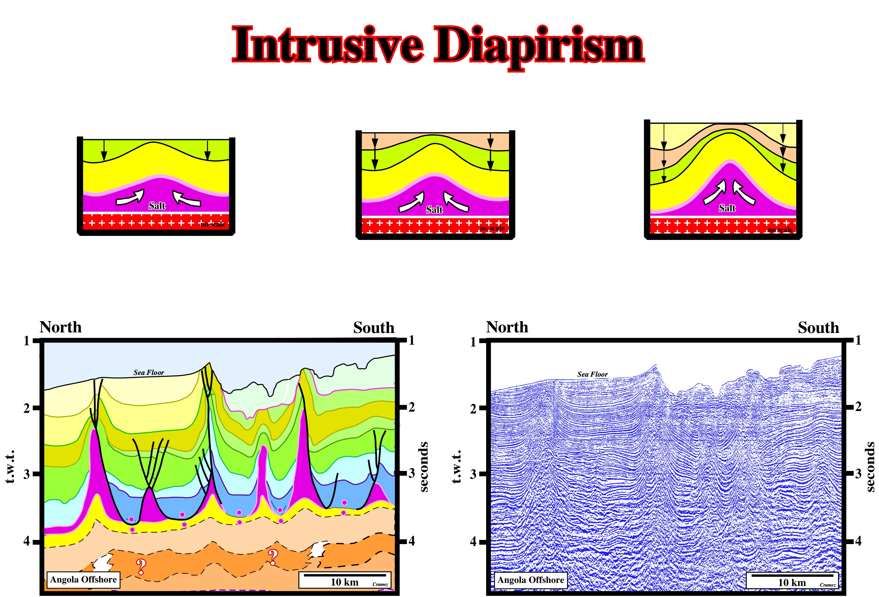
Salt domes are intrusive or extrusive. Intrusive salt domes never outcrop. They do not reach the surface. Extrusive salt domes reach the surface. They induce an apparent diapirism as sedimentation progresses. Intrusive salt domes buckle the sediments of the overburden. Deformation decreases upward. Extrusive domes do not deform all overburden. Overburden deformation stops once the dome reaches the surface. Then, when the dome becomes disconnected from the mother salt layer, upward growing of the dome stops. However, lateral salt displacements are possible. On this tentative geological interpretation of a Canvas autotrace of an Angola offshore seismic line, in which the salt induced pitfall are evident in the subsalt strata,the tectonic disharmony between the infrasalt strata and the cover (salt plus overburden) strongly suggests that halokinesis is dominant. Some of intrusive diapirs seem to be slightly squeezed. Notice, the distance between the salt structures is, more or less, constant.
Inversion Point
Depth point emphasizing a density inversion between salt and sediments. Below the inversion point, the density of the sediments is higher than the density of the salt. On the contrary, above the inversion point, the density of the salt is higher than the density of the sediments.
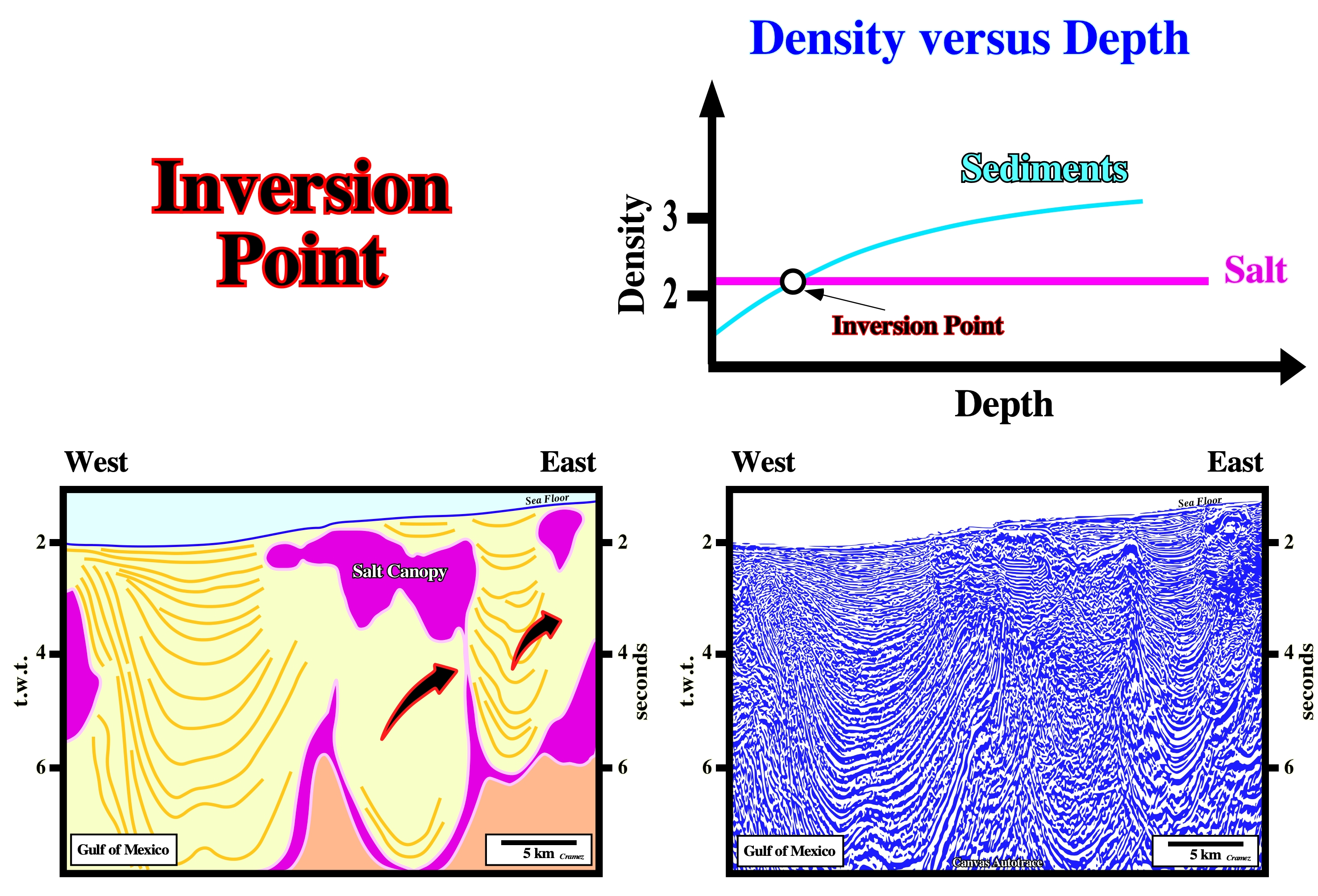
The assessment of the inversion point is quite important. At higher depths, the sediments being denser than the salt, the salt has a tendency to flow upward. Contrariwise, above the inversion point, the salt being denser than the sediments, the salt flows laterally. The pressure than the salt exert against the sediments is not balanced by the sediments.
Isobath
An imaginary line on a land surface or geological map along which all points are at the same vertical distance above or below sea level, or a line in a map or chart connecting points with the same depth.
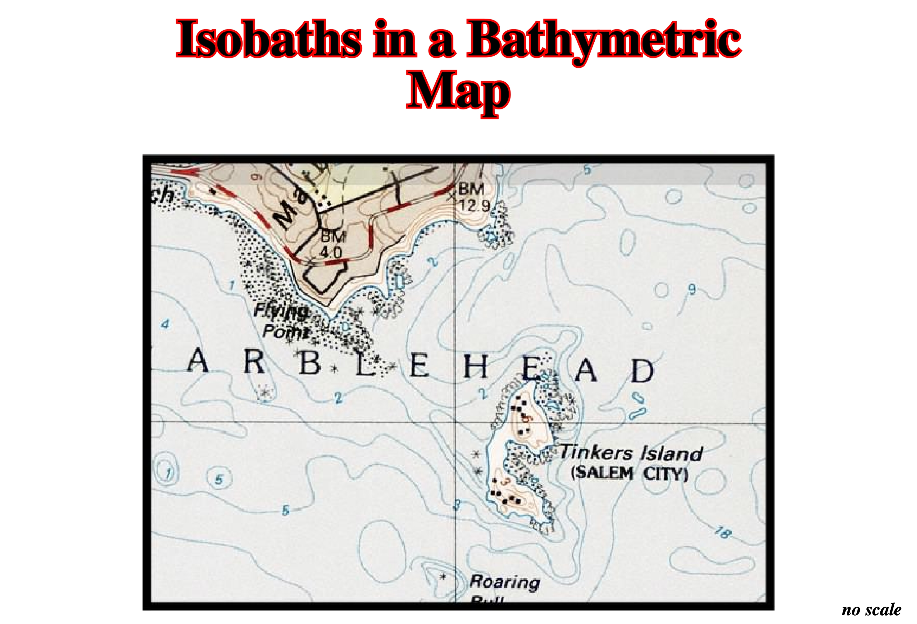
In salt tectonics and particularly in salt basins with allochthonous salt, the morphologic interpretation of bathymetric maps is an useful tool to approach the location and geometry of the salt bodies (see below).
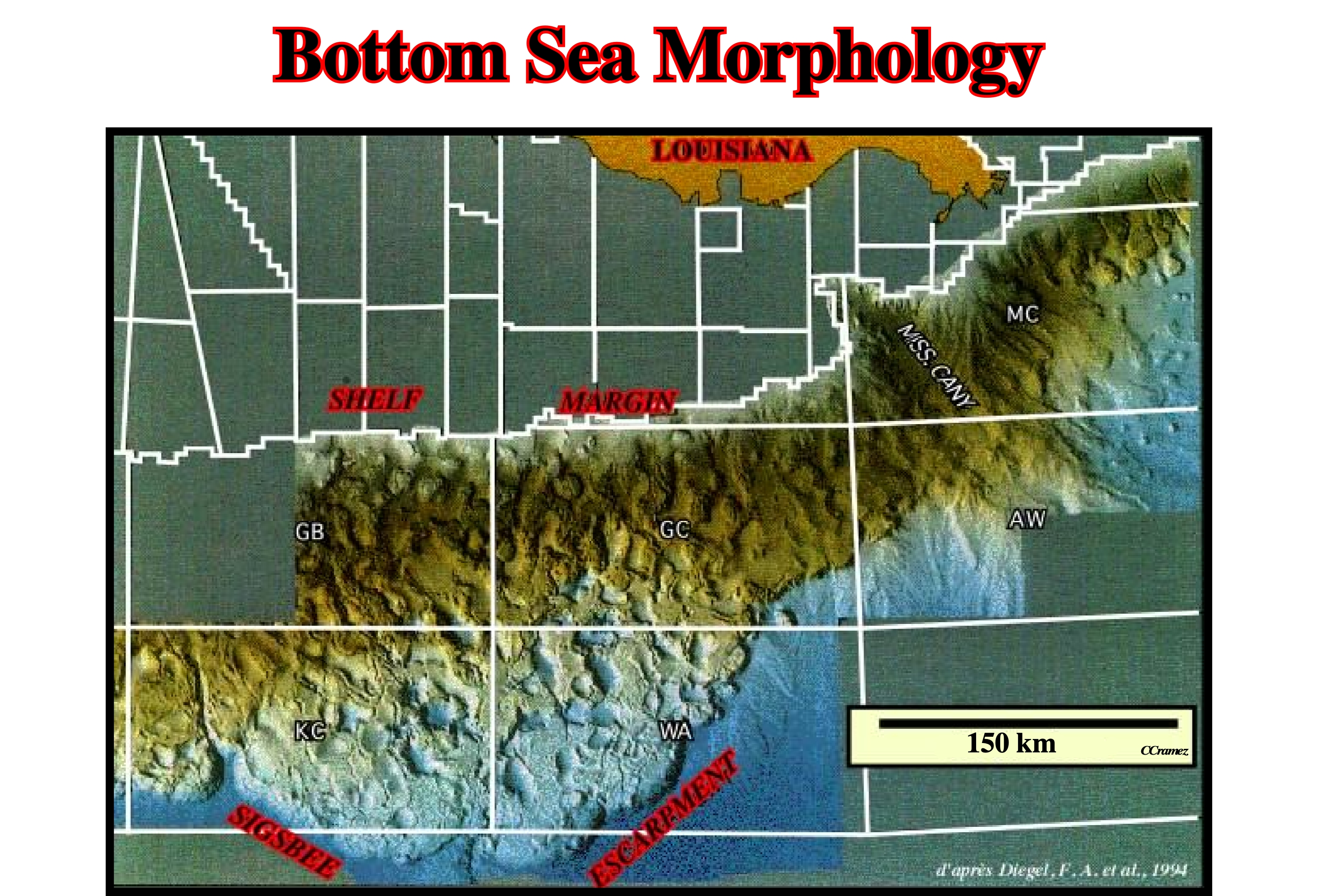
On this artificial illumination of the sea floor of the Gulf of Mexico (NOAA multibeam bathymetric survey), the geometry of the superficial salt structures is easily recognized (vertical exaggeration is 10 x).
Isochoric Flow
Mass transfer of salt over time, resulting in an obvious change in salt area in cross section by unchanged volume flow within the plane of section but beyond the ends of the cross section. Reduction culminates in formation of salt welds or fault welds.
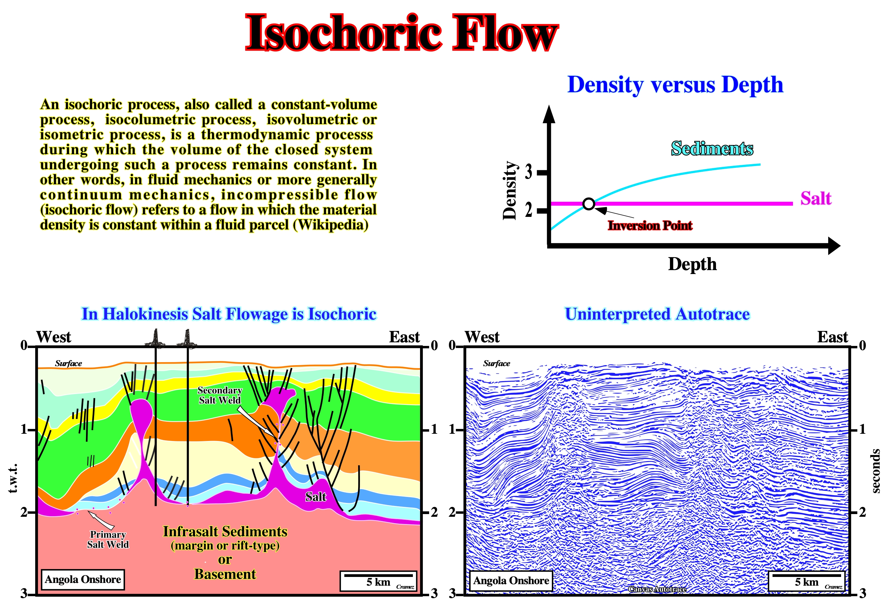
In a tectonic regime characterized by an oblong biaxial effective stresses ellipsoid, i.e., an ellipsoid with σ1 vertical and σ2 and σ3 horizontal and equals, when a salt layer is present, due to the salt properties (buoyancy and incompressibility), it can be deformed by lateral or vertical flowage, creating a compensatory subsidence, which will control the accommodation of the synkinematic sediments. The salt flowage as the illustrated on the tentative geological interpretation (Angola onshore Canvas autotrace) corresponds to an isochoric flow since, as depicted above, the density of the salt does not change in depth.
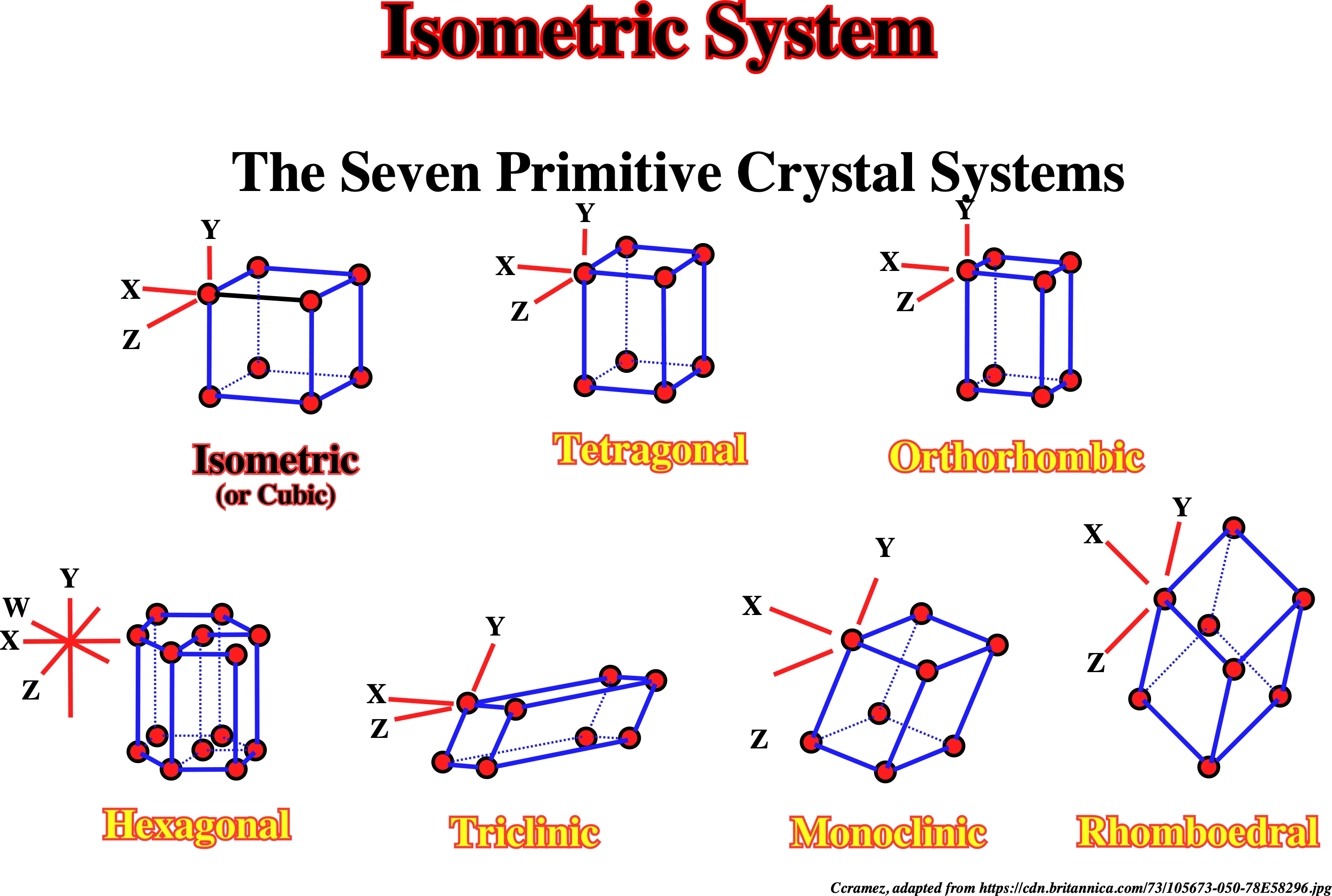
Isometric System (McNeill, L. et al., 1999)
One of the seven primitive crystal systems, characterized by four threefold axes of symmetry as body diagonals in a cubic unite cell of the lattice. It comprises five crystal classes or point groups: (i) Isometric system ; (ii) Tetragonal system, (iii) Orthorhombic system, (iv) Hexagonal system ; (vi) monoclinic system ; (v) triclinic system and (vii) Rhomboedral system. It is synonym of cubic system.
Above are illustrated the seven primitive crystal systems, which are characterized as follows: (i) Isometric or Cubic System- all three axes are equal in length and all are perpendicular to one another ; (ii) Tetragonal System- Two of the three axes are equal in length and all three axes are perpendicular to one another ; (iii) Orthorhombic System- All three axes are unequal in length and all are perpendicular to one another , (iv) Hexagonal System- Of four axes, three are of equal length, are separated by equal angles, ans lie in the same plane ; the four axis is pericardia to the plane of the three others ; hexagonal cells lace lattice points in each of the two six-sided faces (https://cdn.britannica.com/73/105673-050-78E58296.jpg) ; (v) Triclinic System- All three axes are unequal in length and none of perpendicular to another ; (vi) Monoclinic System - all three axes are unequal in length and two of them are perpendicular each other an (vii) Rhomboedral System-all three axes are of equal length and none of them is perpendicular to another, but the crystal faces all have the same size and shape.
Isopachous Layer
Synonym of Prekinematic layer.
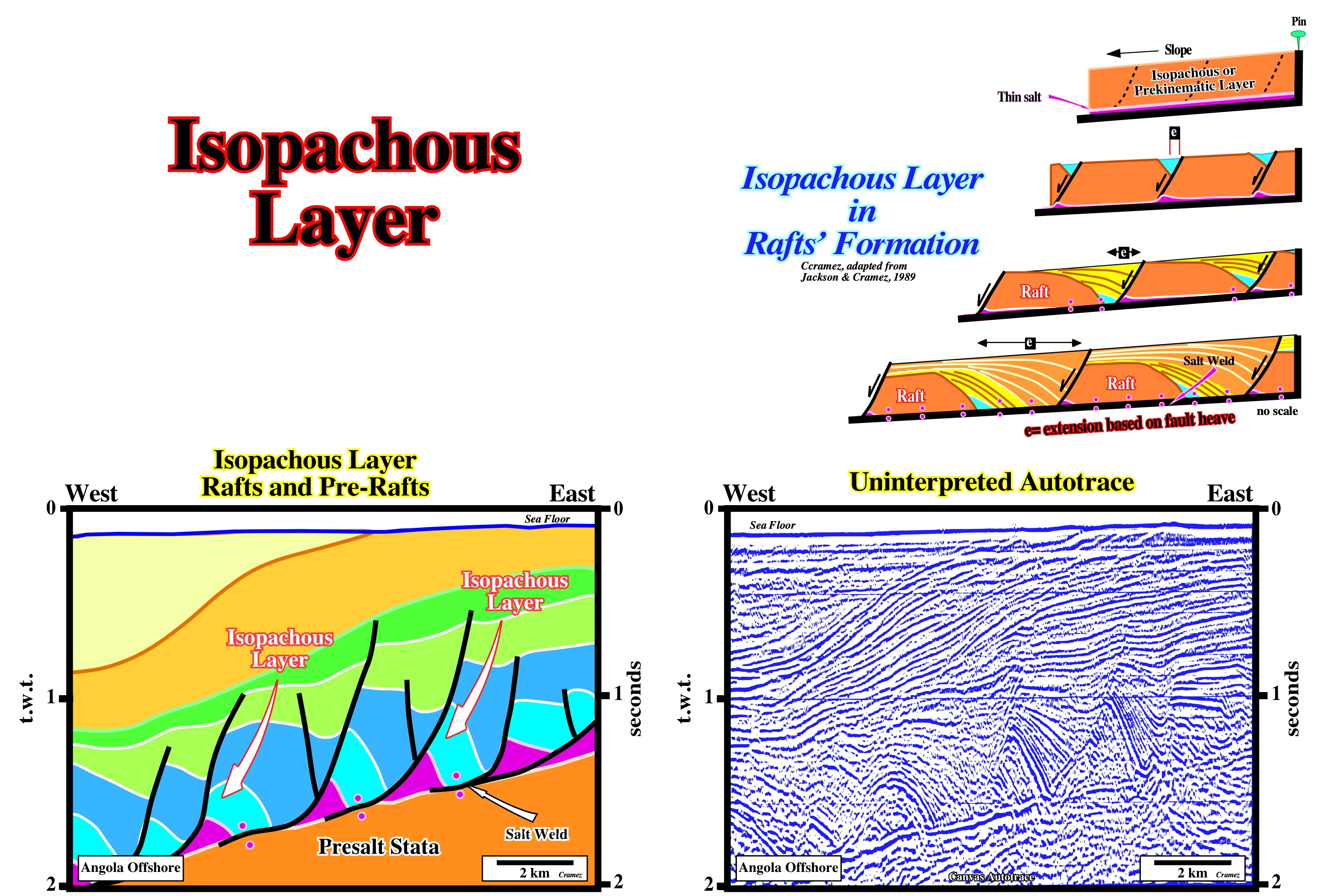
The rafts' formation depicted above can be summarized as follows: a) An isopachous overburden overlies a thin salt (both are slightly tilted), which is, obviously, a prekinematic interval ; b) The salt and the overburden are lengthened by normal faulting with onset of synkinematic trough-like depocenters ; c) The internal configuration of the depocenters is, generally, landward divergent (the chronostratigraphic intervals thick toward the normal-faults, i.e., growth-faults) ; c) The down-thrown blocks of prekinematic (isopachous) interval , i.e., the hangingwalls of the overburden glide down-dip, increasing the size of the synkinematic depocenters ; d) With increasing of the fault heaves, the sedimentary lengthening reaches a point where the blocks of isopachous overburden become rafts by complete disconnection ; e) The blocks begin to be disconnected, i.e., the hangingwalls do not rest anymore on their original footwalls. On the tentative geological interpretation of a Canvas autotrace of an Angola offshore seismic line rafts and pre-rafts are easily recognize. Rafts do not rest on their original up-thrown blocks (footwall). Pre-rafts are rafts, which are not completely disconnected.
Isotropic
A medium whose properties are the same in all directions.
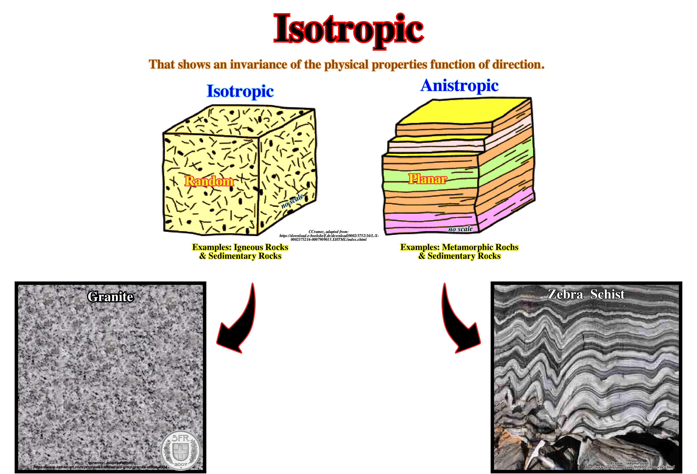
On this subject, we can read in https://www.nde-ed.org/EducationResources/CommunityCollege/Materials/Structure/anisotropy.htm: "In a single crystal, the physical and mechanical properties often differ with orientation. It can be seen from looking at our models of crystalline structure that atoms should be able to slip over one another or distort in relation to one another easier in some directions than others. When the properties of a material vary with different crystallographic orientations, the material is said to be anisotropic. Alternately, when the properties of a material are the same in all directions, the material is said to be isotropic. For many polycrystalline materials the grain orientations are random before any working (deformation) of the material is done. Therefore, even if the individual grains are anisotropic, the property differences tend to average out and, overall, the material is isotropic. When a material is formed, the grains are, usually, distorted and elongated in one or more directions which makes the material anisotropic. Material forming will be discussed later but let’s continue discussing crystalline structure at the atomic level."