
Facies (Gressly, A., 1883)
A lithology and the associated fauna. A sedimentary facies can be defined as a mass of sedimentary rock, which can be defined, and distinguished from others, by its lithology, geometry, sedimentary structures, paleocurrent pattern and fossils. As pointed out by Selley (1970), it is very important to distinguish a sedimentary environment from a sedimentary facies. One should say sand facies in a deltaic environment rather than sandstones deposited in a fluvial facies or in a turbidite facies.
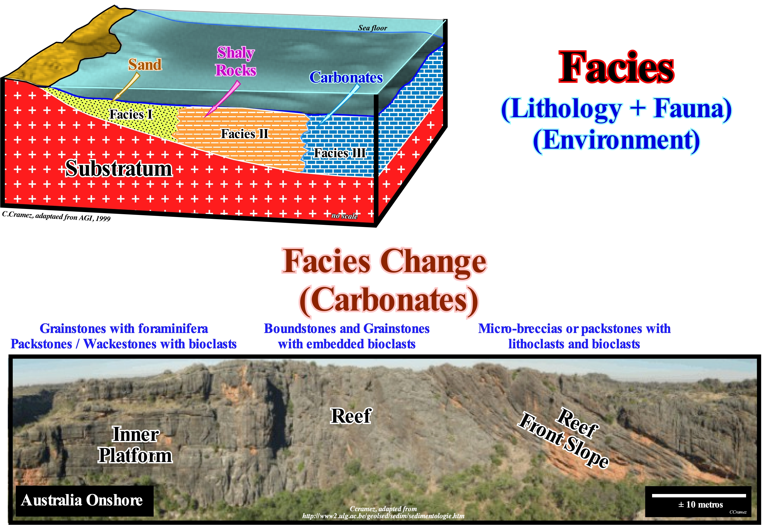
Term facies was used by Gressly, in 1838, to express a lithology and the associated fauna. This term has lost much of its original meaning. Frequently, geoscientists, particularly American geoscientists use the term facies to express the shape, appearance, and deposit conditions, that is, more or less, synonymous with sedimentary environment. For instance, they say, "an interval of deltaic facies sand," while a European geoscientist says "a sand facies interval from a deltaic environment". One facies, as illustrated in this figure, corresponds to a restricted part of a lithostratigraphic unit. It can be mapped. It differs from the other parts, deposited at the same time, in continuity of sedimentation, by the lithology and fossils and, sometimes, by the depositional environment. The texture, composition and structural characteristics of a sedimentary deposit result mainly from the accumulation and modification of a particular environment. The concept of facies refers to the sum of the characteristics (usually on a small scale, centimeters or meter) of a sedimentary unit. Facies associations form several facies that occur in combination and typically represent a depositional environment (note that many individual facies are characteristic of a particular context). Facies successions (or sequence of facies) are associations of facies with a characteristic vertical order. Walther's law says different facies, laterally synchronous, overlap, vertically, each other without unconformity (erosional surface) between them.
Family
Adjoining salt walls or salt stocks comprising more than one generation of diapir. The secondary peripheral sink of the mother diapir laterally merges with the primarily peripheral sink of the daughter diapir, the same relationship holds for succeeding offspring. The secondary peripheral sinks of each generation are thus imbricated. The family comprises diapirs of different ages rooted in the same source layer. This relationship contrasts with generations of salt structures distributed vertically, each generation of salt sheet providing a new source layer for the next secondary-cycle and third-cycle diapirs.
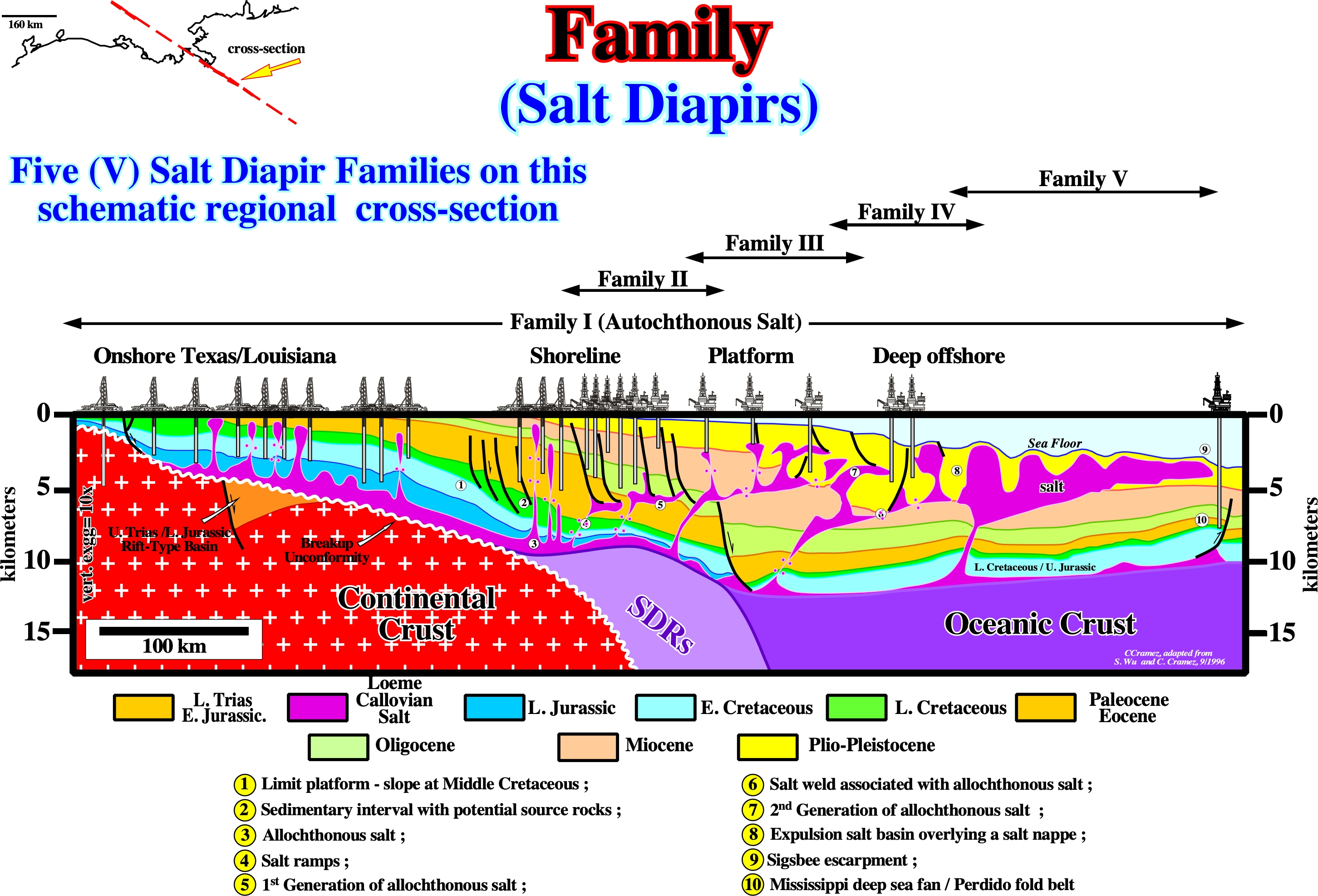
On this NW-SE Gulf Coast schematic geological cross-section, five families of salt diapirs are easily recognized. The salt mother rock (salt source layer) for Family I is the autochthonous salt, i.e the salt diapirs are rooted in the autochthonous salt layer. For diapirs of the others families the salt source layer rock is associated a different salt nappes (source layers), i.e., the salt diapirs of each family are rooted in a characteristics salt nappe. As recognized above, excepting family I (autochthonous salt) all others families have a progradational distribution, which suggest they are associated different sedimentary loadings. The family V, for instance, seems to be associated with Plio-Pleistocene, depocenter, while Family IV seems to be induced by the Miocene depocenter, etc.
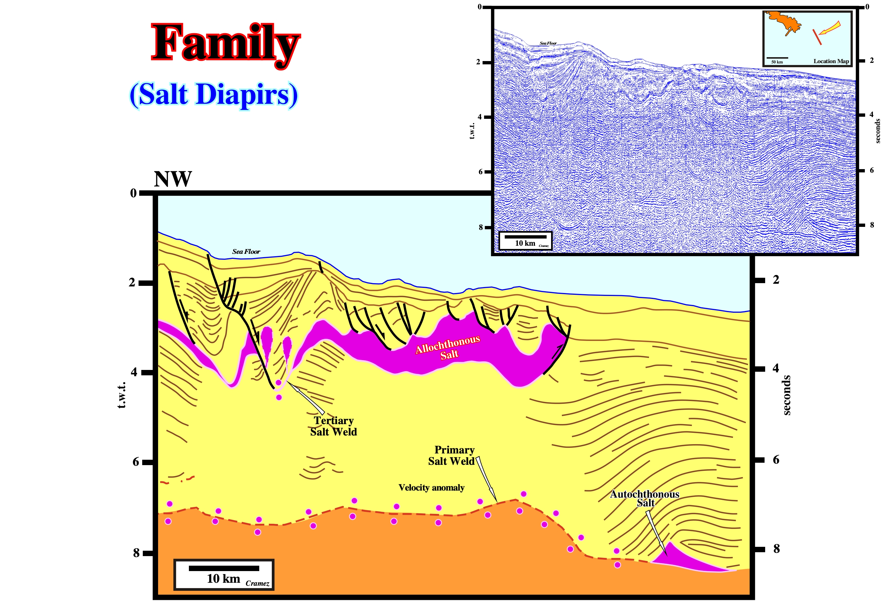
On this preliminary tentative geological interpretation of a Canvas autotrace of a Gulf of Mexico seismic line, the salt structures associated to the allochthonous salt belong to the family III of the previous figure (probably associated with the Paleocene-Eocene loading). The salt ramp along which the salt of the source layer (autochthonous salt) flowed upward is located westward of the seismic line.
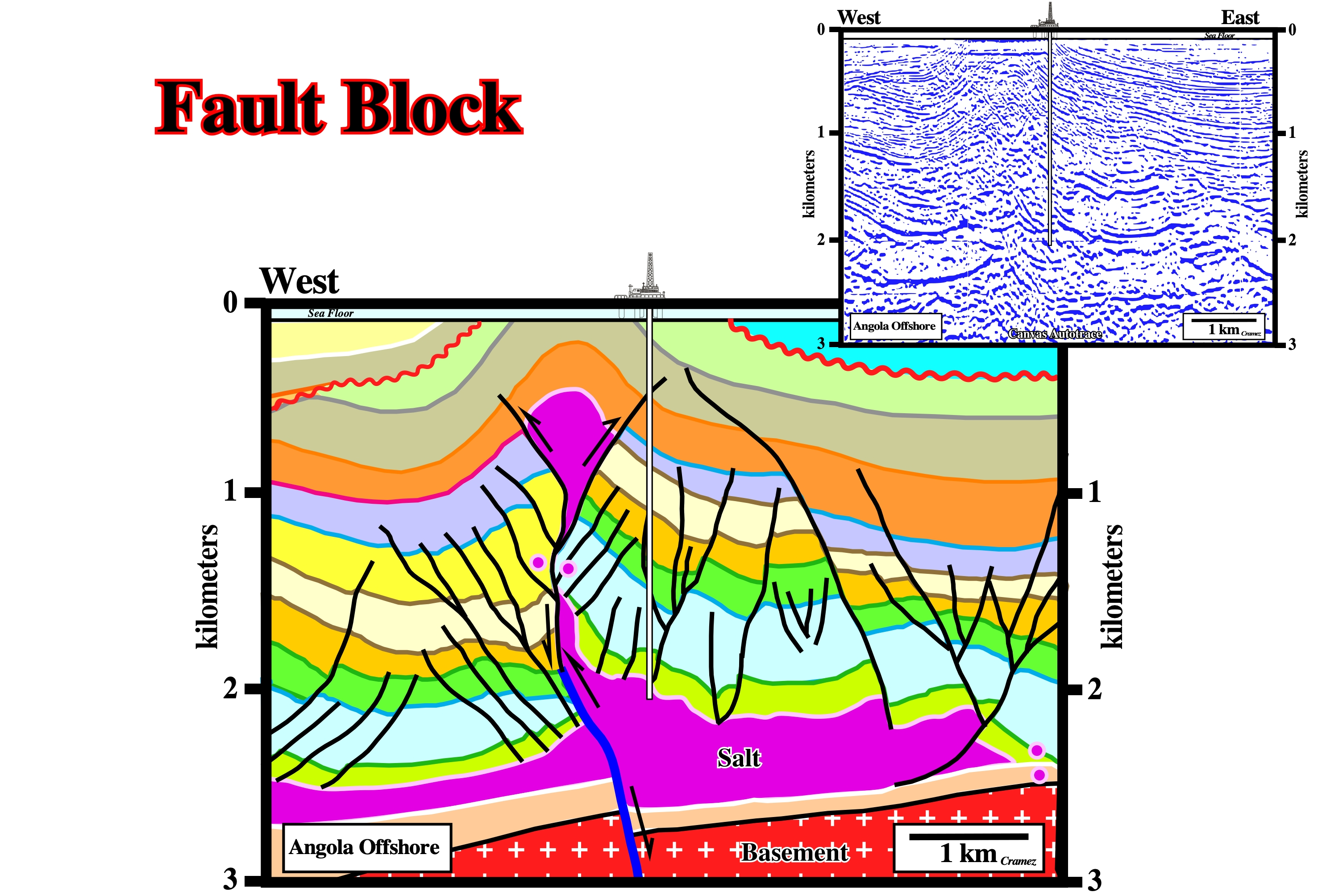
Fault Block
A block of the crust that has been displaced by movement on a fault. Fault block is mainly used when the dip of the fault plane is unknown, that is to say when the footwall or hangingwall cannot be recognized.
On this tentative geological interpretation of a Canvas autotrace of an Angola offshore seismic line (conventional offshore), a major fracture zone created two fault blocks. The movement of these blocks changed with time. Basically, the movement of the faulted blocks is in strike-slip. Certain times it has a compressional (shortening ) and sometimes an extensional component (lengthening). The eastern fault block, for instance, is the hangingwall, during certain time-periods and the footwall during others. As a consequence of these different movements, a depocenter developed in the western block, when it plays as hangingwall, and the salt diapir developed in association with the fracture. The salt diapir, finally, was squeezed with the formation of a vertical secondary salt weld and a salt anticline on the top. The last compressional movement responsible of the salt anticline, clearly, deformed the cryptic eustatic unconformity (erosional surface induced by a relative sea level fall), which became, locally, a tectonically enhanced unconformity that certain geoscientists call angular unconformity.
Fault Cutout
See: Basal cutoff.
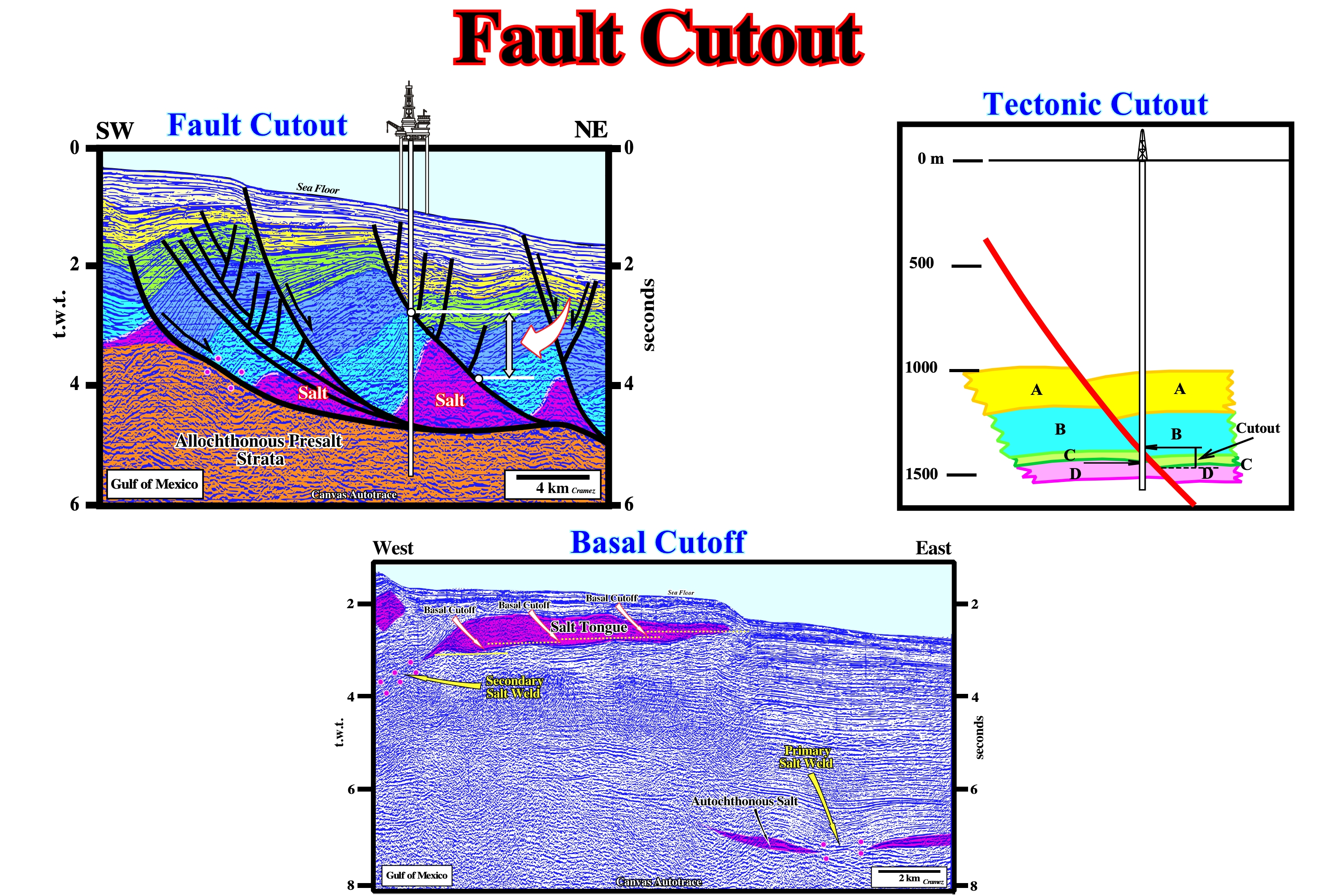
It is important not confuse fault cutout with basal cutoff. Fault cutout (tectonic cutout) is associated with normal faulting, particularly, with growth faults. The basal cutoff is associated with the base of a salt tongue in its upward and outward movement. Each basal cuttoff marks the successive positions of the leading edges of the spreading tongue at successive stratigraphic times. The continuous and post-depositional movement along a normal fault plane produces a "rollover" closure due to the "potential void ". All fault planes of growth faults have less dip at depth than at the surface. Therefore, a concave-upward geometry, as illustrated on the tentative geological interpretation of the Canvas autotrace of a Gulf of Mexico seismic line, is developed. The mapping of these faults planes shows a spoon geometry (curvilinear geometry) rather than a rectilinear geometry. Another particularity of normal faulting (growth faults included) is the impossibility to determine the tectonic or fault cutout in wells results by lack of reference as illustrated above in the geological model. A combination of seismic and subsurface data interpretation can, correctly, approach the thickness and lithology of the interval not recognized by the wells.
Faulting
The process of fracturing and displacement that produces a fault.
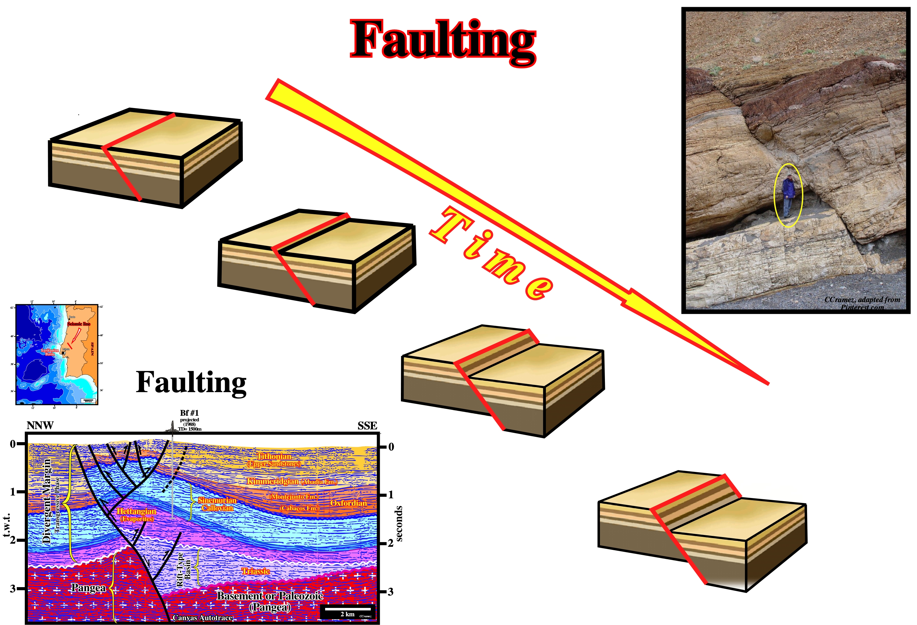
Four steps of faulting along a post-compaction normal fault are illustrated. When a fault is pre-compaction, the dip of the fault is affected by the different compaction of the stratigraphic intervals. A shale interval, for instance, is much more compactable than a sand or limestone interval, so the dip of the fault plane in juxtaposition with shales interval lower in relation to the horizontal.
Fault Weld
Fault surface or fault zone joining strata originally separated by autochthonous or allochthonous salt. It is equivalent to a salt weld along which there has been significant slip or shear.
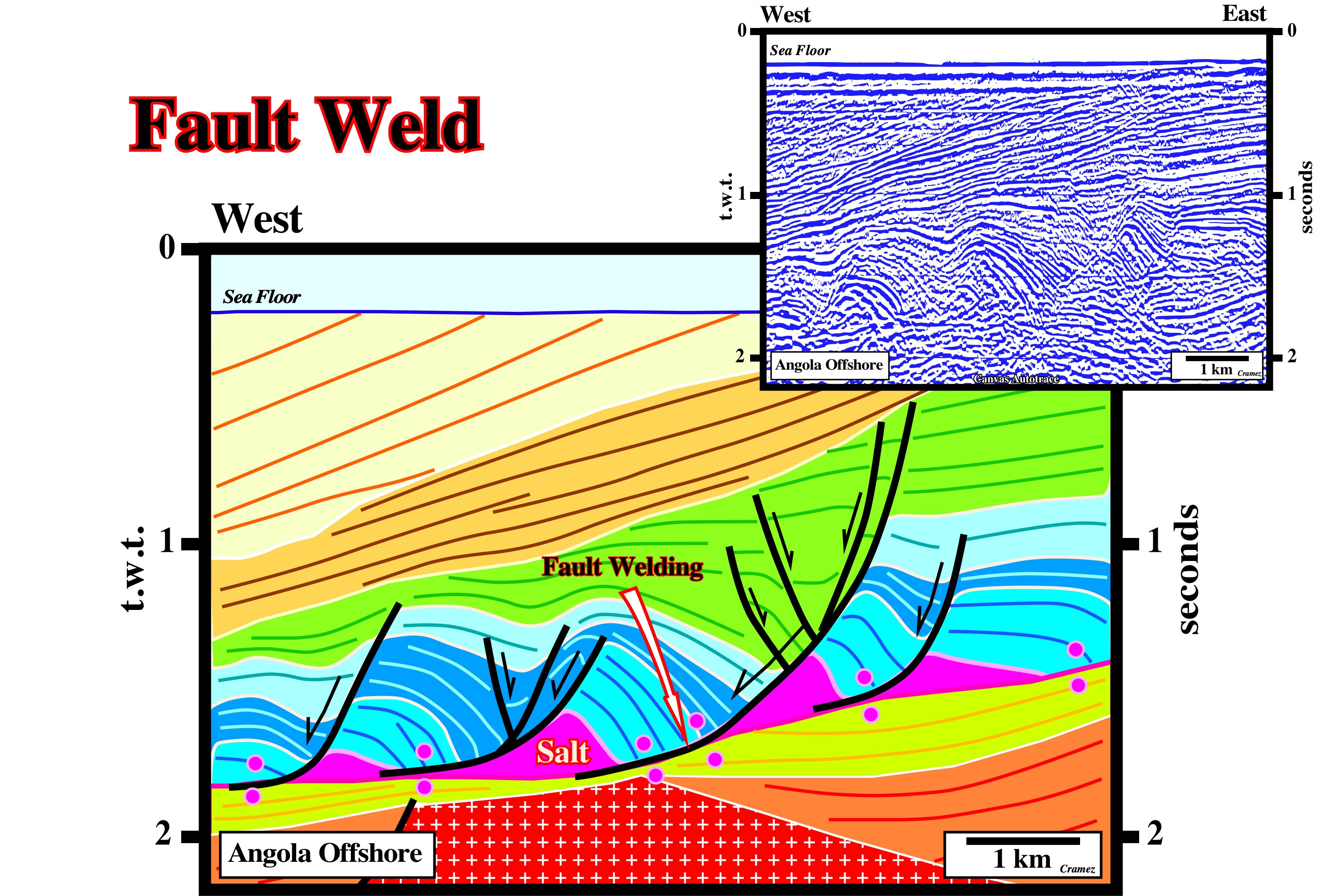
Fault welds ("cicatrices salifères" in French) were first defined in onshore and offshore Angola, from where the seismic line of this Canvas autotrace comes. The movement along the fault welds is, generally, easy to date using the internal configuration of the different sedimentary packages. In this particular example, it is quite evident the seaward movement was initiated during the dark blue interval (synkinematic layer) since the first blue interval (prekinematic layer) is roughly isopach (no compensatory subsidence).
Feeder
Counter-regional fault, which is, often, interpreted as a feeder of allochthonous salt structures.
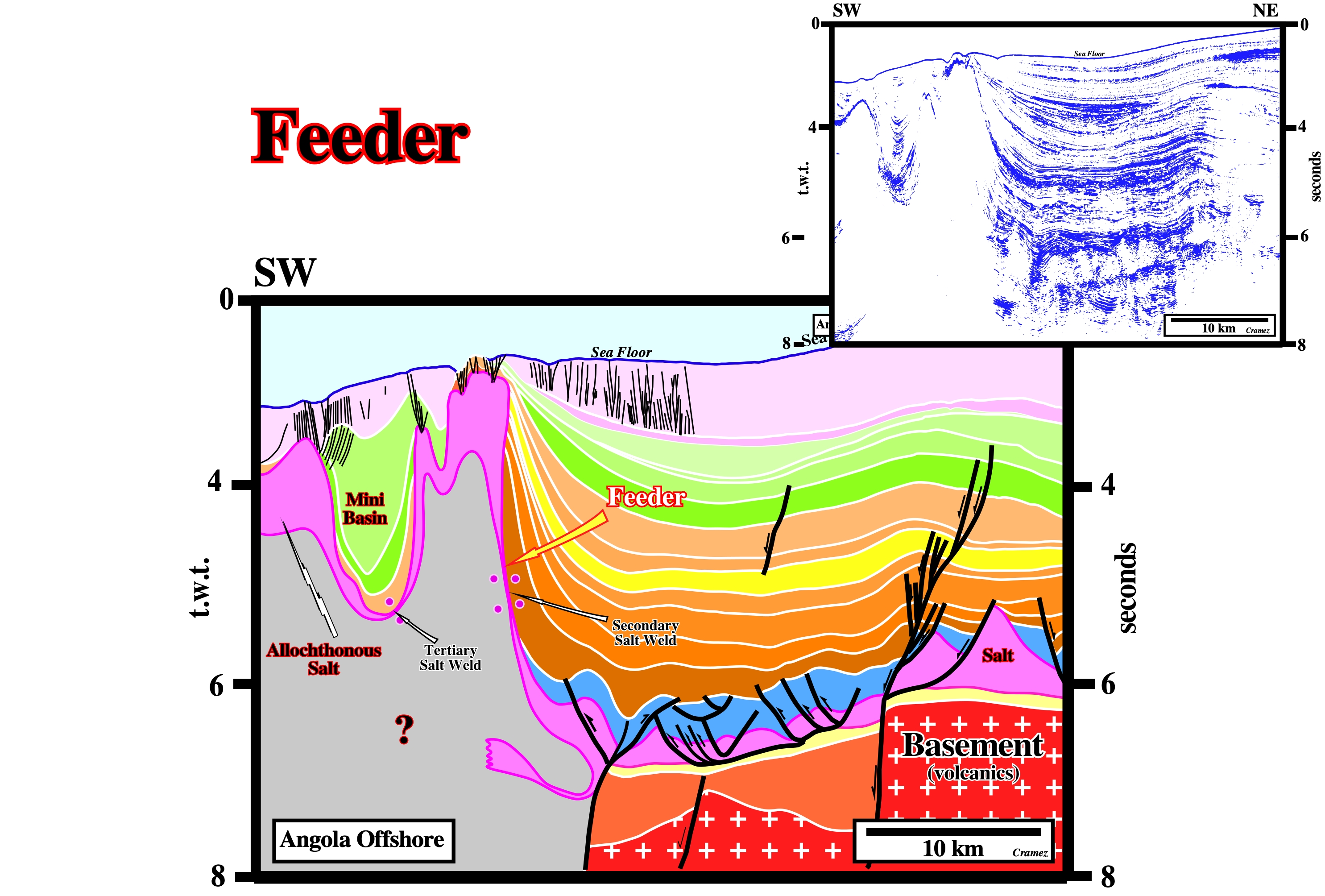
On this interpretation geological interpretation of a Canvas autotrace of an Angola offshore seismic line, the salt in the counter-regional fault or salt weld (generally a more or less vertical secondary salt weld), underlined by the arrow, is just a interpreter's suggestion of the connection between the allochthonous and autochthonous salt layers. In other words, it is suggested than the counter-regional faults is a feeder of the allochthonous salt structure.
Feldspar
A group of abundant rock-forming minerals of general formula: M{Al(Al,Si)3O8}, where M=K, Na, Ca, Ba, Rb, Sr or Fe. Feldspars are the most widespread of any mineral group and constitute 60% of the Earth's crust. They occur as components of all kinds of rocks (crystalline schists, migmatites, gneisses, granites, most magmatic rocks) and as fissure minerals in clefts and druse mineral cavities.
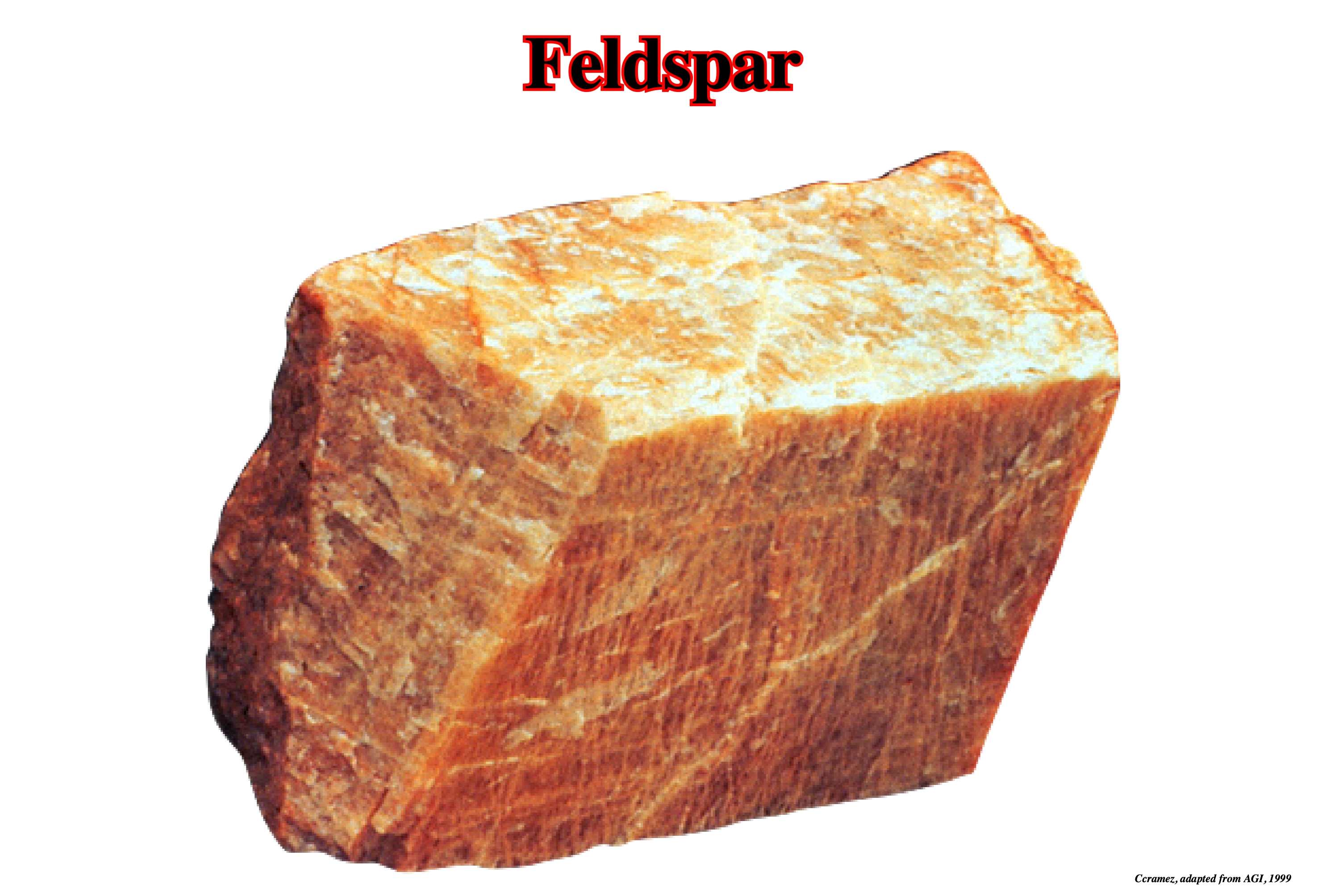
Feldspars are, usually, white or nearly white and clear and translucent (they have no color of their own but are frequently colored by impurities), have a hardness of 6 on the Mohs scale, frequently display twinning, exhibit monoclinic or triclinic symmetry, and possess good cleavage (tendency of a mineral to break along smooth planes parallel to zones of weak bonding, while a fracture is tendency of a mineral to break along curved surfaces without a definite shape) in two directions (intersecting at 90° as in orthoclase and about 86° as in plagioclase). In decomposition, feldspars yield a large part of the clay of soil and also the mineral kaolinite.
Finite Strain
A finite change in shape or volume of a body as a result of stress. The final state of finite strain can be considered as being made up of a large number of incremental or infinitesimal strains.
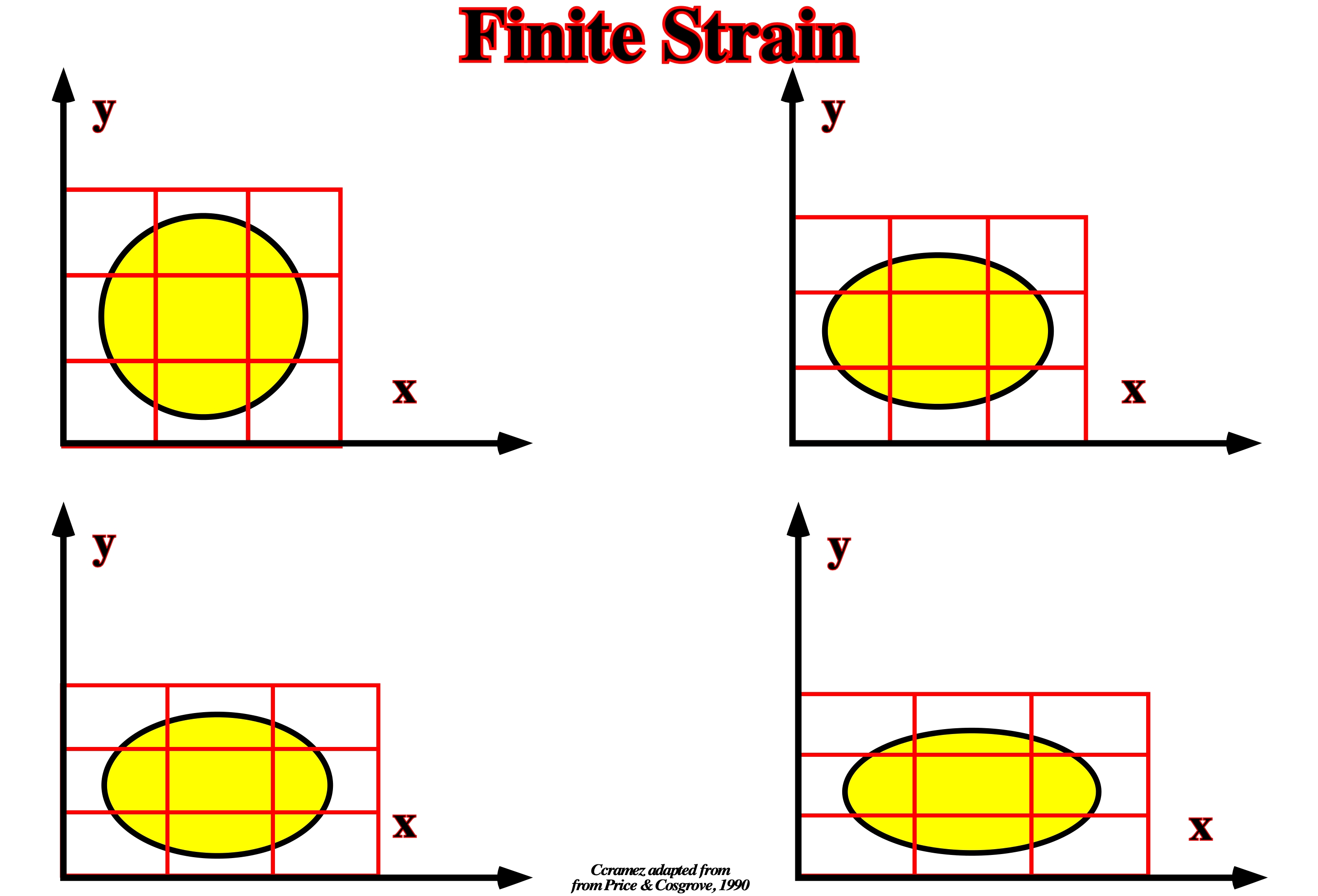
Various stage in pure shear deformation. Such deformations involve no area change. There are three principal strains: (i) Longitudinal, change in length per unit length (e.g. when stretching a wire) ; (ii) Volume, change in volume per unit volume (e.g. when a hydrostatic pressure is applied to a body) ; (iii) Shear, angular deformation without change in volume (e.g. a rectangular block strained so that two opposite faces become parallelograms, the others not changing shape).
First Generation Diapir
Diapir growing from the autochthous salt layer.
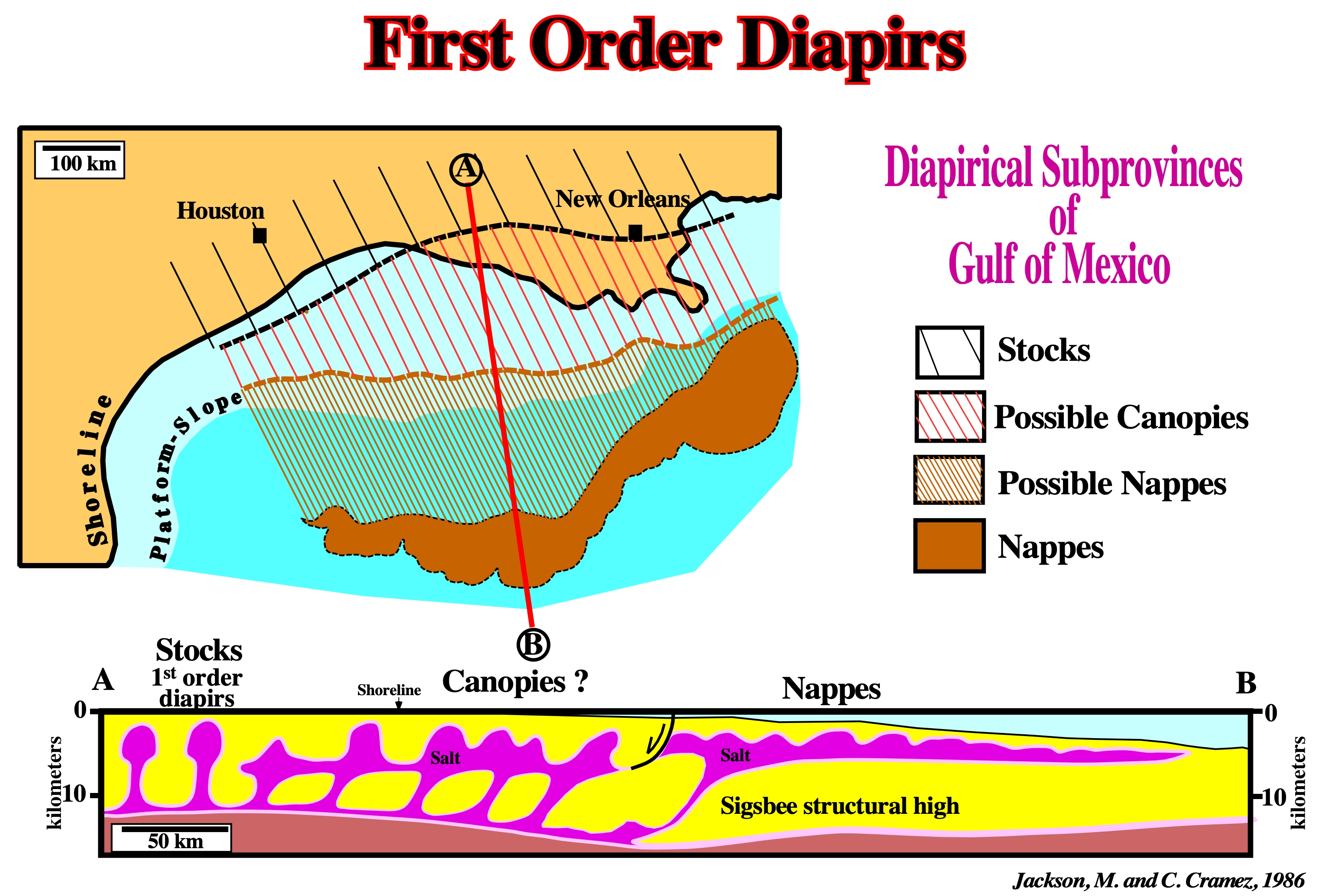
As illustrated on this geological cross section through Gulf of Mexico, several diapiric subprovinces can be put in evidence. The salt stocks correspond, often, to first generation diapirs.
First-Order Cell
Cell that contains several diapirs within it and which may be as large as an entire sedimentary basin.
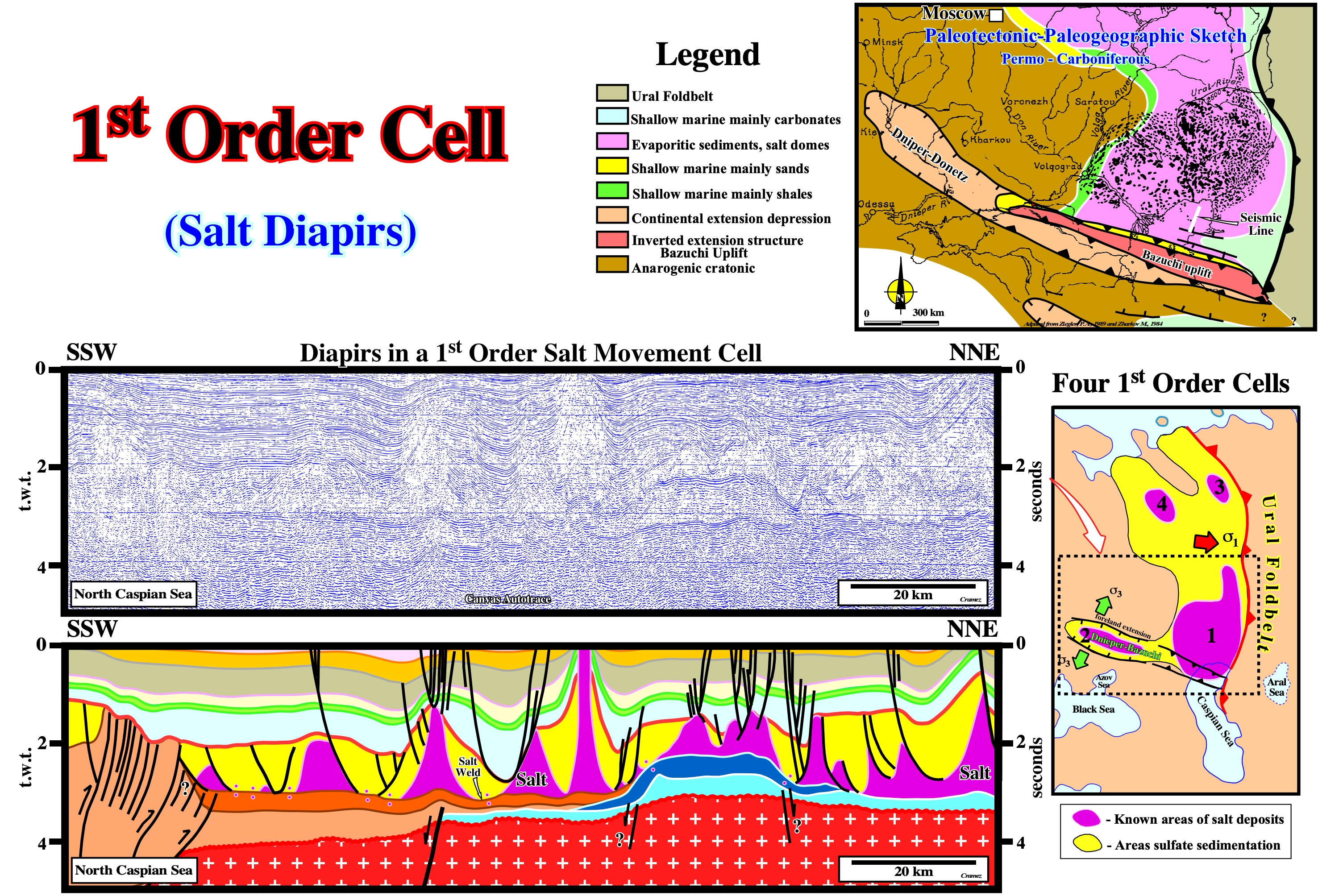
In 1987, Talbot and Jackson using the stepwise centrifuge for modeling the salt movement cells, i.e., to model the volume containing close loops of streamlines (laminar flow lines for which the tangent at any point is the local, instantaneous, velocity vector of flow) or stream surfaces in an overturning system of source layer and overburden. They considered three order cells: (i) 1st order cell, which contains several diapirs within it and which my be as large as an entire sedimentary basin ; (ii) 2nd order cell, which is at the scale of a diapir (the center of the cell is the diapir, in which the streamline rises, whereas its lateral margins are defined by the outer limits of the sinking streamlines) and (iii) 3rd order cell, which affects just a part of a single diapir, as, for instance, in the growth of the mushroom diapir bulbs. At macroscopic scale (scale of the geological maps and seismic lines), it seems possible to use the same terminology. In East European Permian Geographic Salt Basin, it reasonable to consider four 1st order cells, being the larger located southward of the Ural Foredeep (South Pricaspian geographic basin). The tentative geological interpretation of the Canvas autotrace of a regional seismic line of North Geographic Caspian Basin illustrates the southern part of the 1st order salt cell.
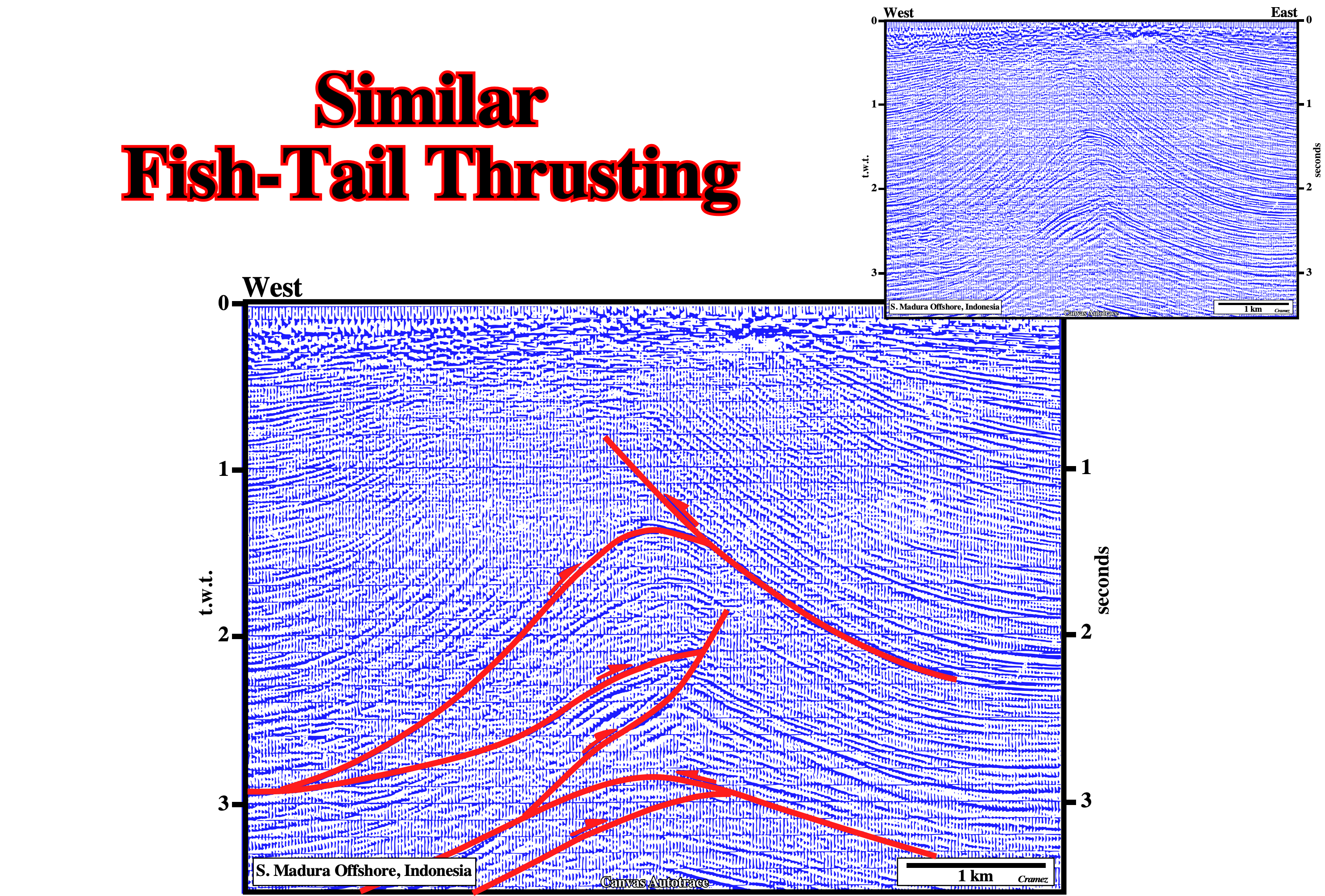
Fish-Tail Thrusting
Detachment fold with a fish-tail geometry in an upper detachment.
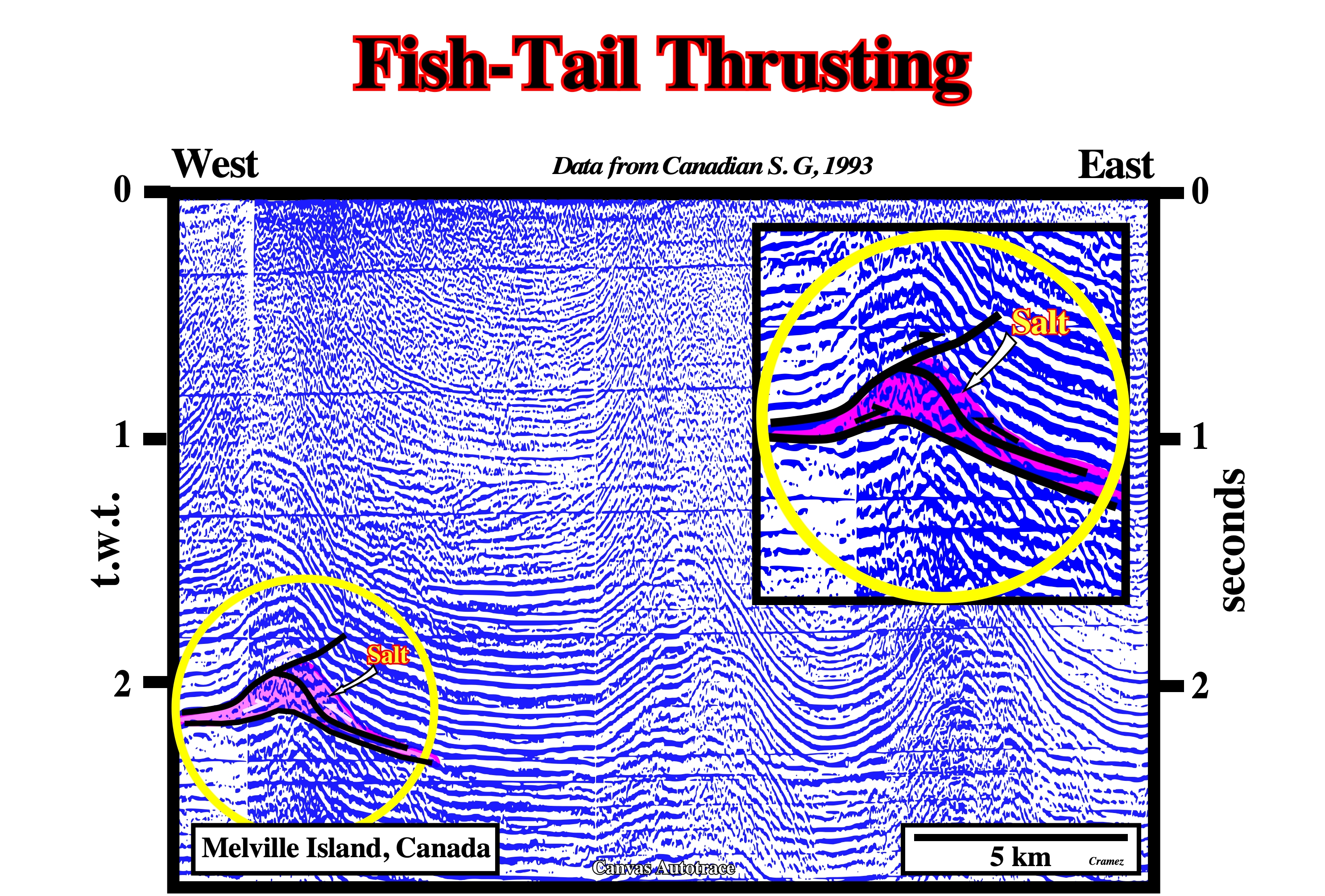
Fish-tail thrusting structures, above a salt layer, are quite frequent, in Melville Island from where the lines, used to make this Canvas autotrace, comes.
As illustrate on this preliminary tentative interpretation of a Canvas autotrace of a seismic line of S. Madura offshore (Indonesia), one of the characteristics of the fish-tail structures is the fact the geometry of the upper seismic intervals is quite simple (a simple anticline in this example), but it becomes quite complicated in depth, (several faulted-anticlines with opposite vergence, separated by decollement surfaces) due probably to problem space reasons.
Flap (Upturn reflection termination) (M. Rowan et al., 2003)
Sedimentary structure with the form of flap, with a strong inclination on the sides of the salt diapir or againt prekinematic strata. Can correspond to deformed onlaps due to the salt movement (and compensatory subsidence) or created by the broken roof of an active diapir, which due to the salt movement is moved aside or eroded.
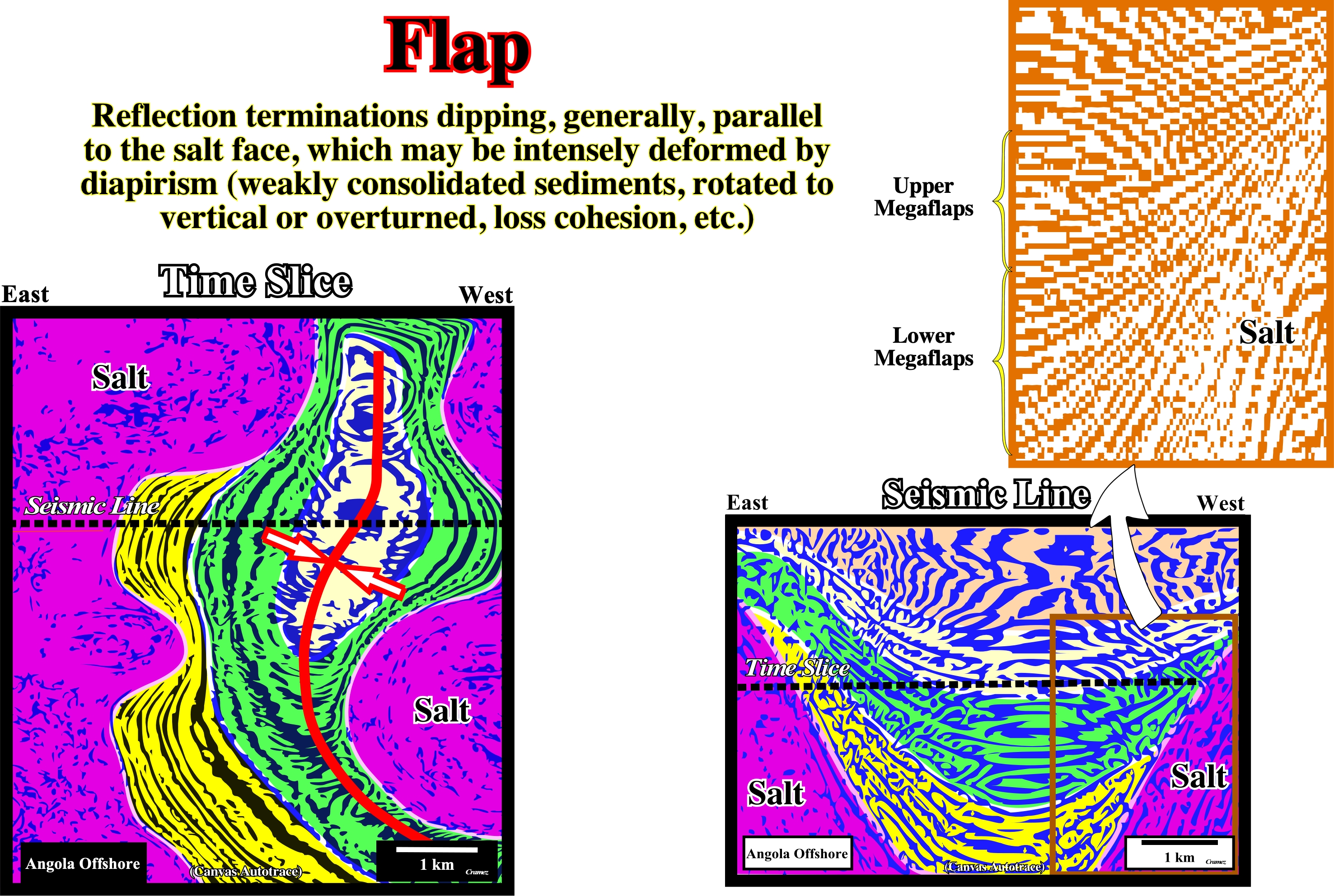
In relation to the proposed salt models, on the tentative geological interpretations of the seismic lines (or Canvas autotraces), the recognition and understand of the sediments flapened is, often, made using the interface salt - synkinematic overburden or the interface between prekinematic and synkinematic sediments of the overbank. Generally, three types of sediment flap can be recognized, mainly, on seismic data and particularly on 3D data: (i) Basal flats (often megaflaps) ; (ii) Perched flaps and (iii) Contractional flaps (associated to injection salt anticlines). According to M. Rowan (2012), the basal megaflaps (thick sedimentary interval) are upturned at the base of a diapir and thin upward along the diapir flank (see tentative interpretation of Canvas autotrace of Angola offshore), they can pinchout or be, partially, eroded or continue way up to the crest of the diapir and even overturn beneath the breakout of a salt sheet ( M. Jackson, 2017). The perched flaps lie partway up the diapir flanks. They are thinner and smaller than basal megaflaps and form when a diapir breaks through a thinned roof. The third type of flaps (contractional flaps) forms as the limbs of an injection fold which is an active diapir formed in the crest of salt anticlines (no salt antiform), as the anticline amplifies its core is pressured by displacement loading imposed by tightening fold limbs (M. Jackson, 2017). If the overburden is thin enough the salt core breaks out actively to surface.
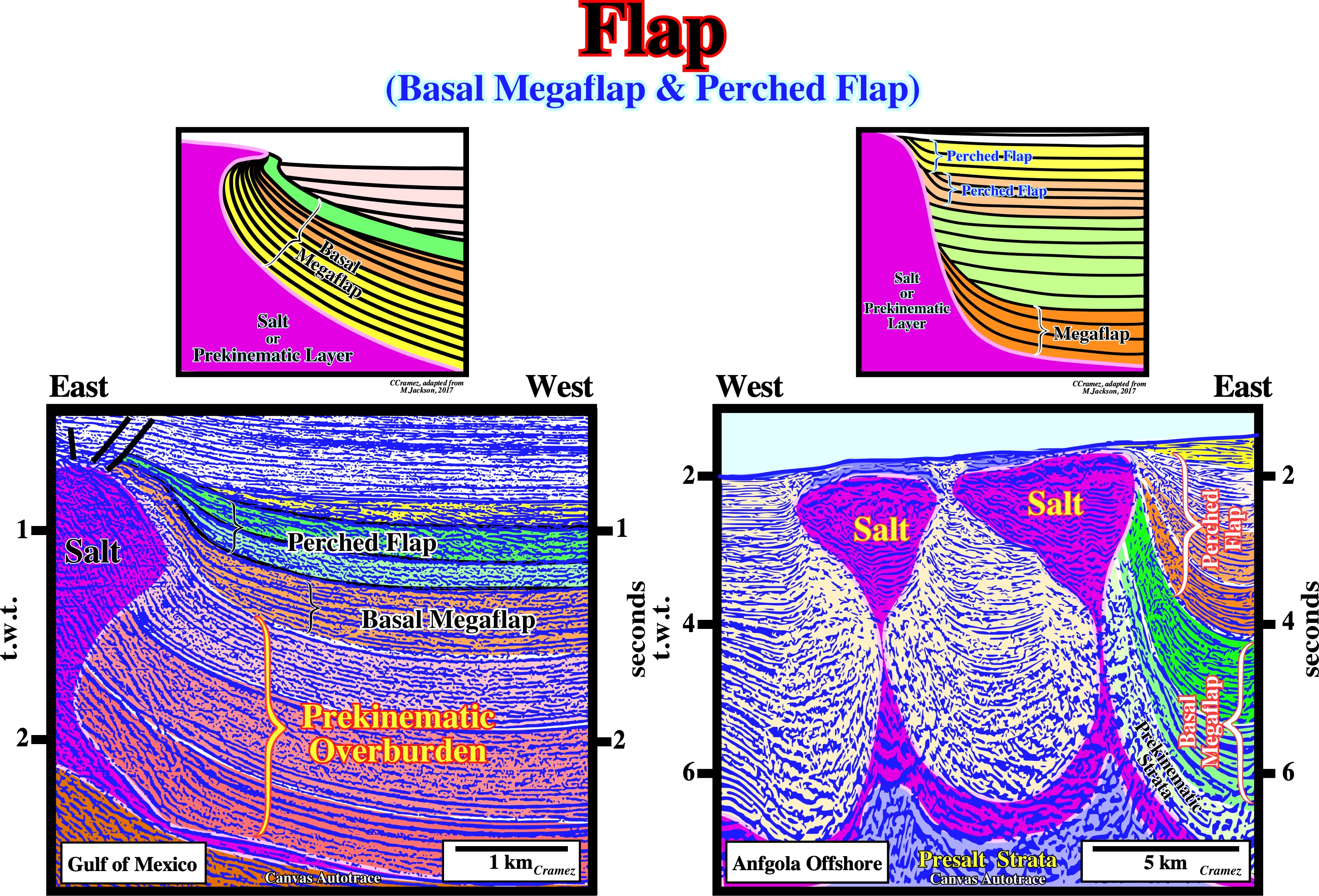
On Canvas autotraces as well as on seismic lines, rarely, the sediments flaps of the overburden are directly against the salt diapir flanks. On contrary, as illustrated above, not only basal megaflap but the perched flaps are easily recognized against the bottom of the top of the prekinematic overburden.
Flaring Regime
When the molding ratio (R°/A°), i.e., flow rate of salt minus dissolution divided by aggradation rate minus compaction, ranges between 100> R°/A°>10. With such a ratios the dip of the bottom contact flares between 0.6° and about 11.5°.
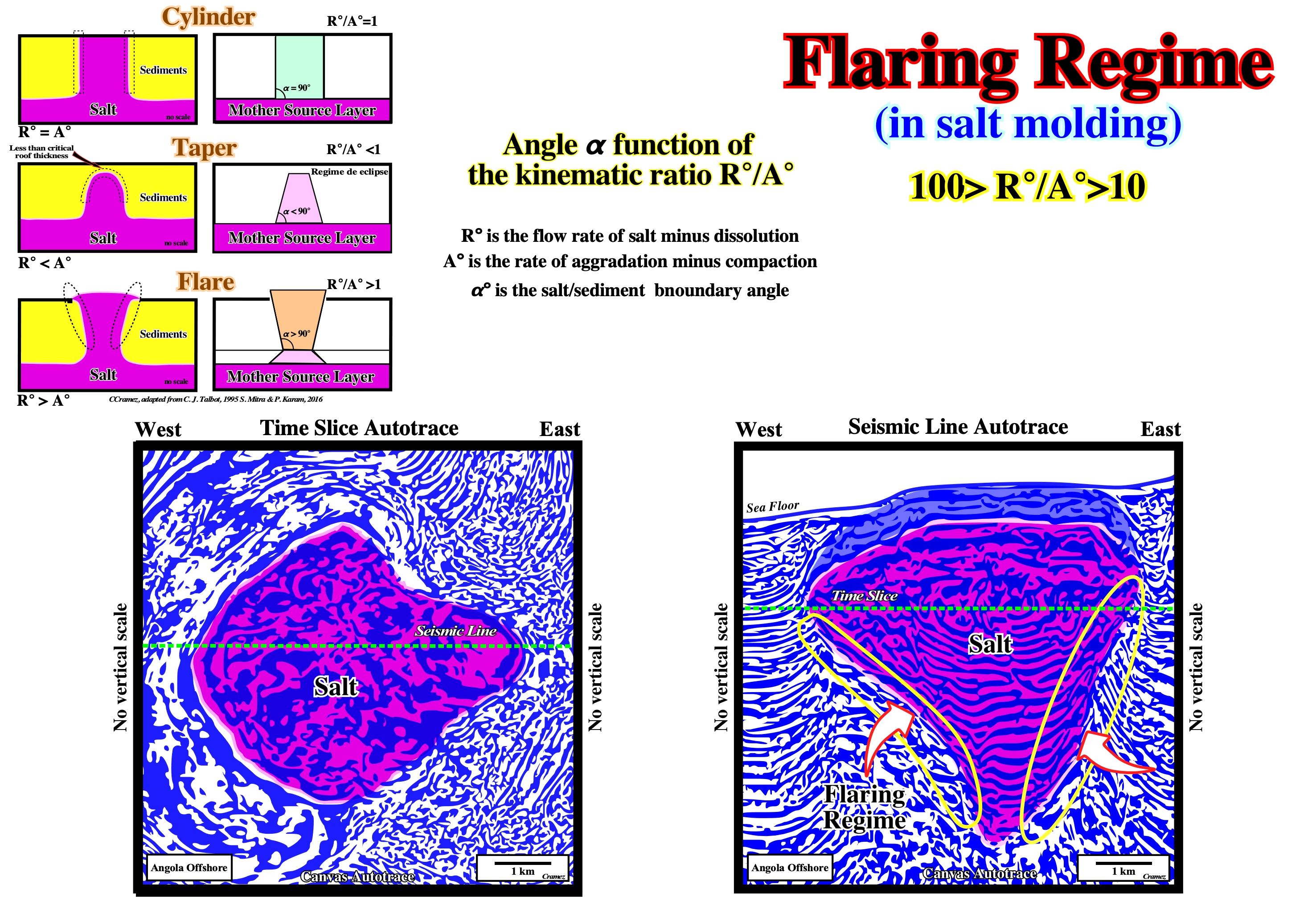
The geometry and evolution of salt diapirs can be defined by angle α° (interface angle between sediments and salt) dependent primarily on the rates of sedimentation (A°) and salt flow (R°): tan ( α° /2) =R°/A°. The geological model suggest tapering and flaring are mechanisms for maintaining an equilibrium between net rates of sedimentation (A°) and salt rise (R°), with changing R°/A° values. Flaring is caused by high R°/A°, but is also an effective mechanism of decreasing the rate of net salt rise by increasing the surface area of the top of the diapir. Tapering is caused by low R°/A°, but is also a mechanism for increasing the rate of salt rise by decreasing the diameter. On this basis, the shapes of salt /sediment boundaries can be classified as tapering, cylindrical, and flaring. When the roof of a diapir is above the critical thickness (± 20 % of the total overburden) the diapir is said to be in a regime of eclipse. On the tentative geological interpretations of the Canvas autotraces, illustrated above, the shapes of the diapirs is interpreted taking into account the interface angle between the salt and sediments in cylinder (Nordkapp) , taper and flare (Gulf of Mexico).
Flexural-Slip Fold
A fold in which the mechanism of folding is slip along bedding planes or along surfaces of foliation. In this type of folds there is no change in thickness of individual strata and the resultant folds are parallel.

Under a compressional tectonic regime (ellipsoid of effective stresses, σ1, σ2, σ3, elongated, i.e., with σ1 horizontal) the sediments are shortened. There are different shortening or folding mechanisms : (i) Buckling ; (ii) Bending ; (iii) Flexure folding ; (iv) Flexural Slip ; (v) Flexural Flow ; (vi) Passive Flow and (vii) Kink folding. (i) The sediments are folded by buckling when σ1 is parallel to bedding ; the strain produced in a stratum is determined by extension around the outer arc and compression in inner arc. (ii) The sediments are shortness by bending when σ1 is across the strata, which are bent like an elastic beam supported at the ends and loaded in the middle ; generally, the folds are gentle with large limb angles. (iii) Flexure folding corresponds to a simple bending due to lateral compression with σ1 horizontal (strata with or without slide one another). (iv) The sediments are folded by flexural slip folds at shallow depth in the Earth's crust by parallel concentric folds (constant layer thickness) formed by buckling or bending with the slip parallel to the bedding with formation of slickensides. (v) Flexural flow, which create similar like folds formed in low to moderate metamorphic, areas requires moderate to high ductility contrast between the layers ; the amplitude and wavelength is, generally , controlled by the original thickness, spacing and strength of the strong layers. (vi) Passive-flow create similar folds (formed in metamorphic rocks with low mean ductility and ductility contrast, as salt, glacial ice and water saturated unconsolidated sediments) involving plastic deformation, in which bedding acts just as a displacement marker ; passive-slip folds are a type of similar folds formed by shearing along planes inclined to layering formed by simple shear and not by pure shear. (vii) Kink and chevron folds have straight limbs and narrow angular hinges. They require local slippage (flexural slip) between layers. They are produced by rotation of set layers on either side of the kink-plane. The layers deform partly by flexural slip. (https://fr.slideshare.net/KManikandanBharath/folding-mechanisms-mani-1).
Flexural-Slip Restorations
See: Inclined simple shear restorations.
In a flexural slip algorithm deformation occurs by unfolding the deformed fault bounded horse by slip along bedding planes (https://en.wikipedia.org/wiki/Section_restoration). This modelling mechanism does represent a real geological mechanism, as shown by slickensides along folded bedding planes. The shape of the unfolded horse is further constrained either by using the restored fault boundary to the previous horse in the restored section of by using an internal pin within the block itself, assuming this was unsheared during the deformation. This algorithm is normally only used in software based restoration. It preserves both area and line length.
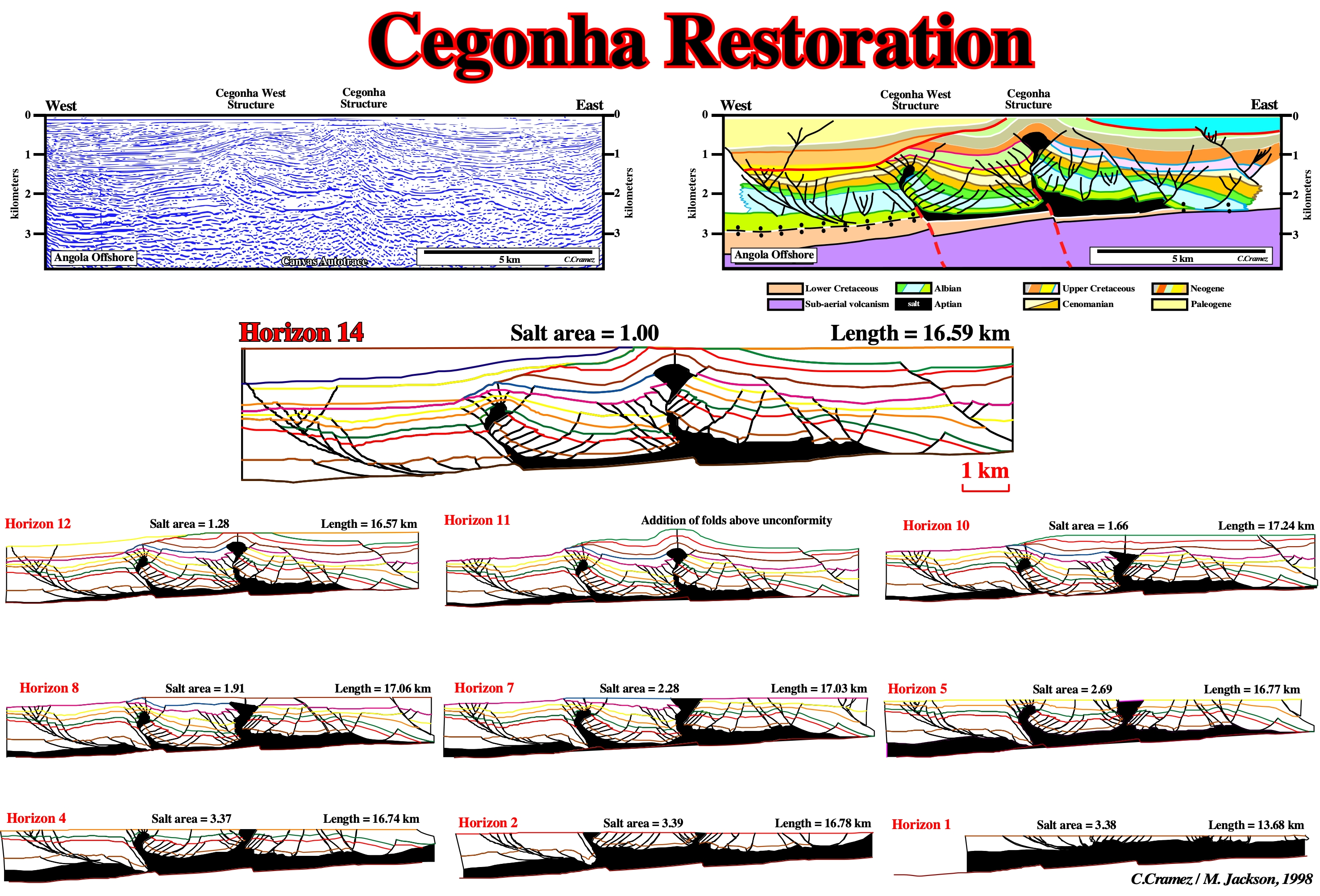
On the tentative interpretation of the Canvas autotrace of the Angola offshore seismic line through the Cegonha structure, the salt tectonics appears to be dominated by contraction. Using the seismic markers picked on the illustrated tentative interpretation and the depicted major steps of the geological reconstruction, it is possible to advance: (i) The two salt walls each form the core of an antiform, which suggests that the contraction is a late-stage overprint ; (ii) The salt walls were initiated extensionally as reactive diapirs; (iii) First the crust tilted seawards along the Atlantic hinge in the mid-Cretaceous soon after the Aptian-Albian salt had accumulated ; (iv) This bending along the hinge line caused local extension of thin overburden above the hinge, which formed two NNE-trending grabens ; (v) The inward-dipping normal faults associated with these are still recognizable ; (vi) The grabens initiated reactive salt walls beneath them, which pierced the thin overburden ; (vii) Soon after, in the Late Cretaceous, regional extension begins ; (viii)The overburden broke into rafts which dispersed seawards over the salt ; (ix) Phase 1 rafting in the late Cretaceous was succeeded by Phase 2 rafting in the early Tertiary (x) During Phase 2 rafting, additional rotation about the Cegonha hinge line further steepened the base of salt in the west ; (xi) West of the hinge line, the overburden extensionally separated into rafts about 10 km long, separated by Tertiary depocenters ; (xii) East of the hinge line, the salt thins landward to a weld beneath an extensional turtle structure ; (xiii) During the early Tertiary, the Cegonha area was anomalously shortened while strata upslope and downslope continued to extend ; (xiv) This shortening we ascribe to local buttressing at the foot of a thin-skinned extensional system decoupling on salt ; (xv)The buttressing was apparently caused by a basement fault scarp below each salt wall ; (xvi) Transpression induced by lateral movements along the major fracture zones can not be excluded ; (xvii) During contraction, overburden strata on the upslope side of each salt wall overthrust the downslope side ; (xiii) Normal faults in each hangingwall were inverted by reverse slip ; (xix) Between the brittle slabs of overburden, the intervening ductile salt was squeezed upward, leaving a secondary fault weld along the thrust and a pressurized diapiric crest supporting the core of an anticline.
Flow Folds
See: Glacial structures.
Folds in incompetent beds that offer so little resistance to deformation that they assume any shape impressed upon them by the more rigid rocks surrounding them or by the general stress pattern of the deformed zone (https://www.mindat.org/glossary/flow_folding).
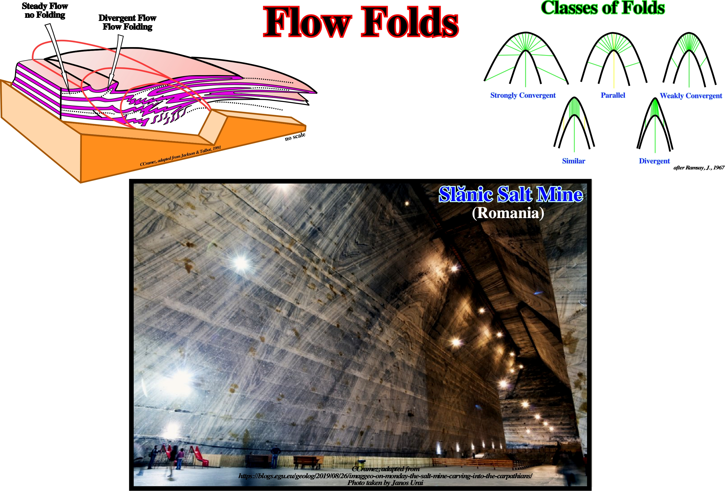
Various classifications of folds have been proposed. The majority are based on the geometry of the fold in profile section, such as the one proposed in 1984 by Van Hise, who considered two large families of folds: (i) Parallel or concentric, in which the orthogonal thickness remains constant and (ii) Similar, in which the folded layers have identical geometry and the thickness measured parallel to the axial plane remains constant. According to Ramsay, J., (1976), it is possible to express the changes in shape within a fold and to classify the folded layer using any of the following parameters: a) Orthogonal thickness t ; b) Thickness parallel to the axial surface T and c) The inclination to the dip isogons (lines on the profile section joining points on a fold of equal dip value). The Slanic Salt Mine (photo) is the largest salt mine in Europe, and the facility consists of 14 large chambers, each more than 50 meters high. The cavities of the mine, more than 200 meters deep, carve into the Southern Carpathian Mountains, offering a unique large-scale view into how the flow folds within the salt strata.
Flow Law For Damp Salt (Jackson, M. P. A., 1995)
Water had long been known to soften salt, but until the 1980s, experimental rock mechanics had focused on the rheology of dry salt, known to deform by dislocation creep. Recently, geologists found that damp evaporites could deform by solution-transfer creep under much lower stresses and much more rapidly than dislocation creep characteristic of dry evaporites. This explained the extraordinarily high flow rates of damp glacial salt. According Roeder (1984) most salt deposits contain traces of saturated brine (inclusion or grain-boundary boundary films). The brine is trapped during deposition or diagenesis of the salt or percolated in as meteoric water into extrusive salt (Jackson, M. and Rudec, M., 2017). When strain rates and differential stresses are low, microstructural processes at grain boundaries are significant in deforming damp rock salt (Urai and Spiers, 2007).
![]()
Janos Urai (2012)proposed this conceptual model of the rock salt cycle and associated rheological transitions. In undisturbed rock salt (1) primary micro-structures reflect the deposition conditions with common micro structure of fluid inclusion outlined grains. In slightly deformed rock salt subgrains develop, together with incipient grain boundary migration (2). As the grain boundary sweeps through a fluid inclusion rich part of a grain, the primary inclusions are collected at the grain boundary. Alternatively, in fine grained salt solution-precipitation creep is dominant. Large contrasts in rheology are common in layered salt, from the onset of tectonic deformation. As the salt rises, and deforms further (3) Steady-state micro-structure is produced after complete recrystallization, although primary fluid inclusions are still preserved. In the cold diapir stem high stress and small subgrains develop (4). At the surface (5) weak mylonitic shear zones form allowing the salt glacier to flow downhill at unusually high strain rates. Finally, dissolution of the salt glaciers in rainwater and redeposition produces secondary evaporites.
Fluid Era (Jackson, M. P. A., 1995)
In the history of salt tectonics three eras can be considered: (i) Pioneering era, between 1856 and 1933, (ii) Fluid era, between 1933 and roughly 1898, and (iii) Brittle era. The fluid era was dominated by the view that salt tectonics resulted from the Rayleigh-Taylor instabilities, in which a dense fluid overburden having negligible yield strength sinks into a less dense fluid salt layer, displacing it upward. Density contrasts, viscosity contrasts ans dominant wavelengths were emphasized, whereas strength and faulting of the overburden were ignored.
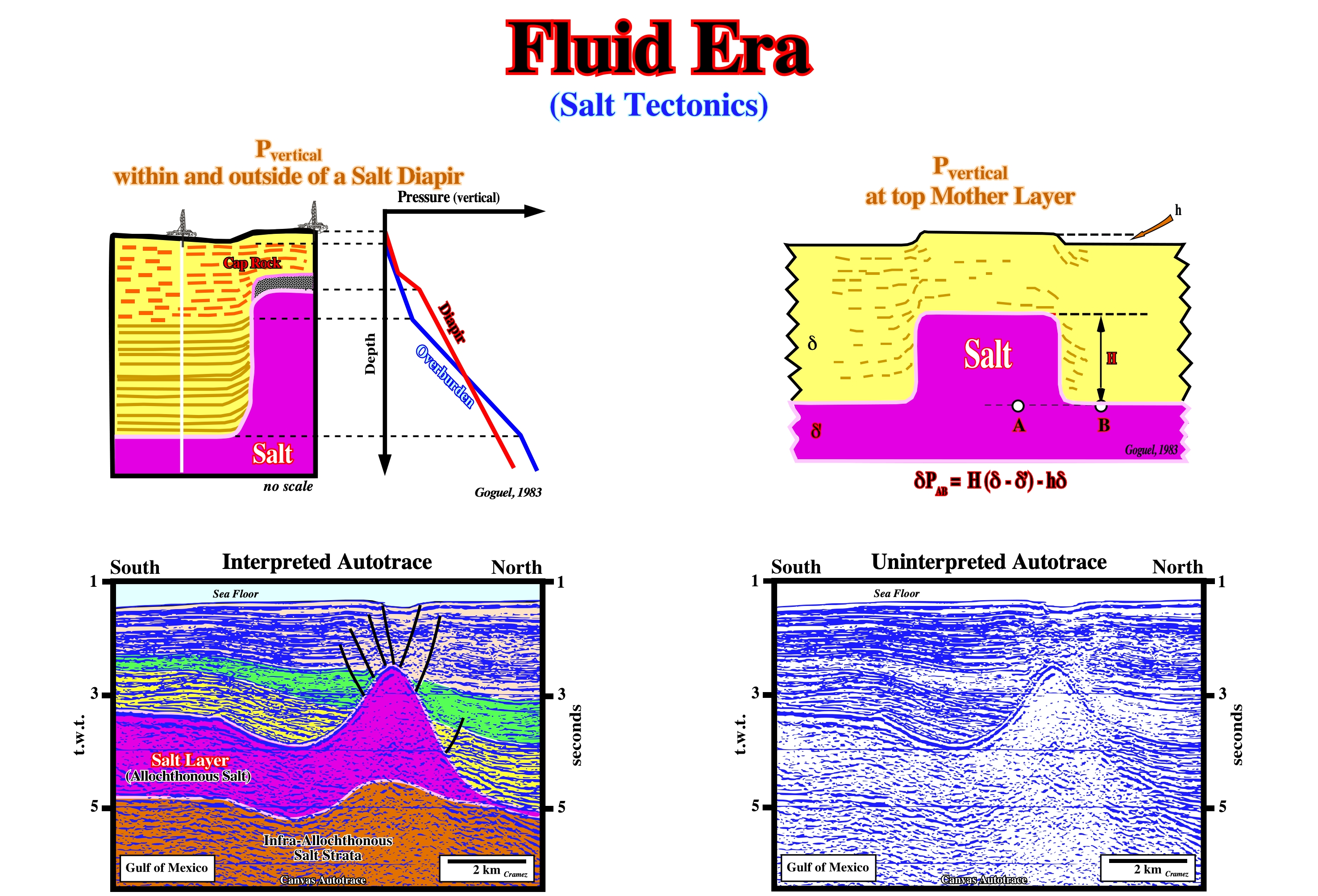
During the salt fluid era, geoscientists, as Jean Goguel, were quit interested in the evolution of the geostatic pressure, which increases in depth function of the average density of the sedimentary layers. Taking into account the wildcats drilled in areas with the presence of significant salt layers as reference, the geostatic pressure shows, in depth, three sharp breaks. They are associated with the stratigraphic boundaries, the last of which is associated with the interface between the overburden and a salt layer (autochthonous salt). Similarly, the geostatic pressure calculated along a hypothetical well through the salt dome, illustrated above, shows two sharp breaks. The first associated with the cap rock and the second with the salt. Within the salt, the geostatic pressure keeps constant, since the density of the salt does not change with the depth. Two profiles of the geostatic pressure (overburden and salt) illustrated on the depth/pressure diagram, define an inversion point. Above this point, the density of the salt is higher than the average density of the overburden. Below the inversion point, the density of the sediments is higher than the salt. In other words, one can say: (i) Above the inversion point, the lateral pressure the salt exerts against the sediments is not balanced by the lateral pressure the sediments exert against the salt ; (ii) Below the inversion point, the lateral pressure that the sediments exert against the salt is balanced by the lateral pressure that the sediments exert against the salt. Additionally, one can say, that a salt dome with vertical sides, as stated previously, is unlikely. Such geometry represents a mechanical instability due to the presence of an inversion density point. The difference between the geostatic pressure of the overburden and that of a theoretical salt dome (ΔPAB) growing from an autochthonous mother layer can be easily calculated. Goguel (1983) knowing: a) The average density of the overburden (d) ; b) The density of the salt (δ’) ; c) The height of the dome (H) ; d) The height of the topographic anomaly induced by the salt dome (h), calculated ΔP using the following formula ΔPAB = H (δ -δ’) - h. The difference of pressure ΔP is one of the driving forces that induce the salt to flow toward the dome until it reaches a pseudo equilibrium state with the overburden. On the seismic example illustrated above the faults on the top of the salt dome were interpreted as a consequence of the upward salt movement, a possible faulting of the overburden was just ignored.
Fold
A curve or bent of a planar structure such a rock strata, bedding planes, foliation or cleavage. A fold is usually a product of deformation, although its definition is descriptive and not genetic and may include primary structures.
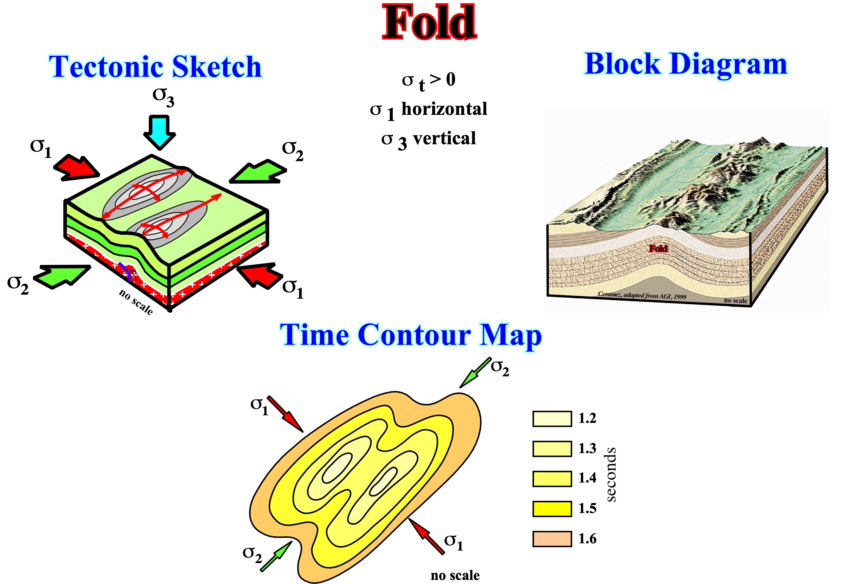
They are easily differentiated when depicted on a stereographic projection. Indeed, on a stereographic projection, the flanks of an anticline lie on a meridian and the axis of the anticline is the pole of the meridian. Fold is a general term and is used in reference to extensional and compressional structures, i.e., structures created by shortening and lengthening. Anticlines are fold created by shortening, while antiforms are folds created by lengthening, in other words, anticlines and antiforms cannot be formed at same time in the same place. Cylindrical folds are the structures created when a sedimentary basin is affected by a compressional tectonic regime with a σ3 (minimum effective stress) vertical. The axes of these structures is parallel to σ2.
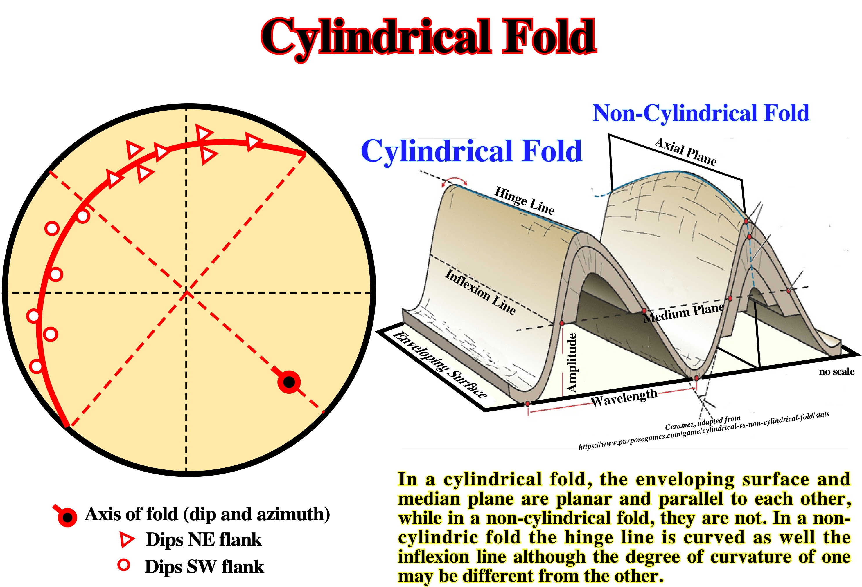
Anticlines can be cylindrical or conical. They are easily differentiated when depicted on a stereographic projection. On a stereographic projection, the flanks of an anticline lie on a meridian and the axis of the anticline is the pole of the meridian.
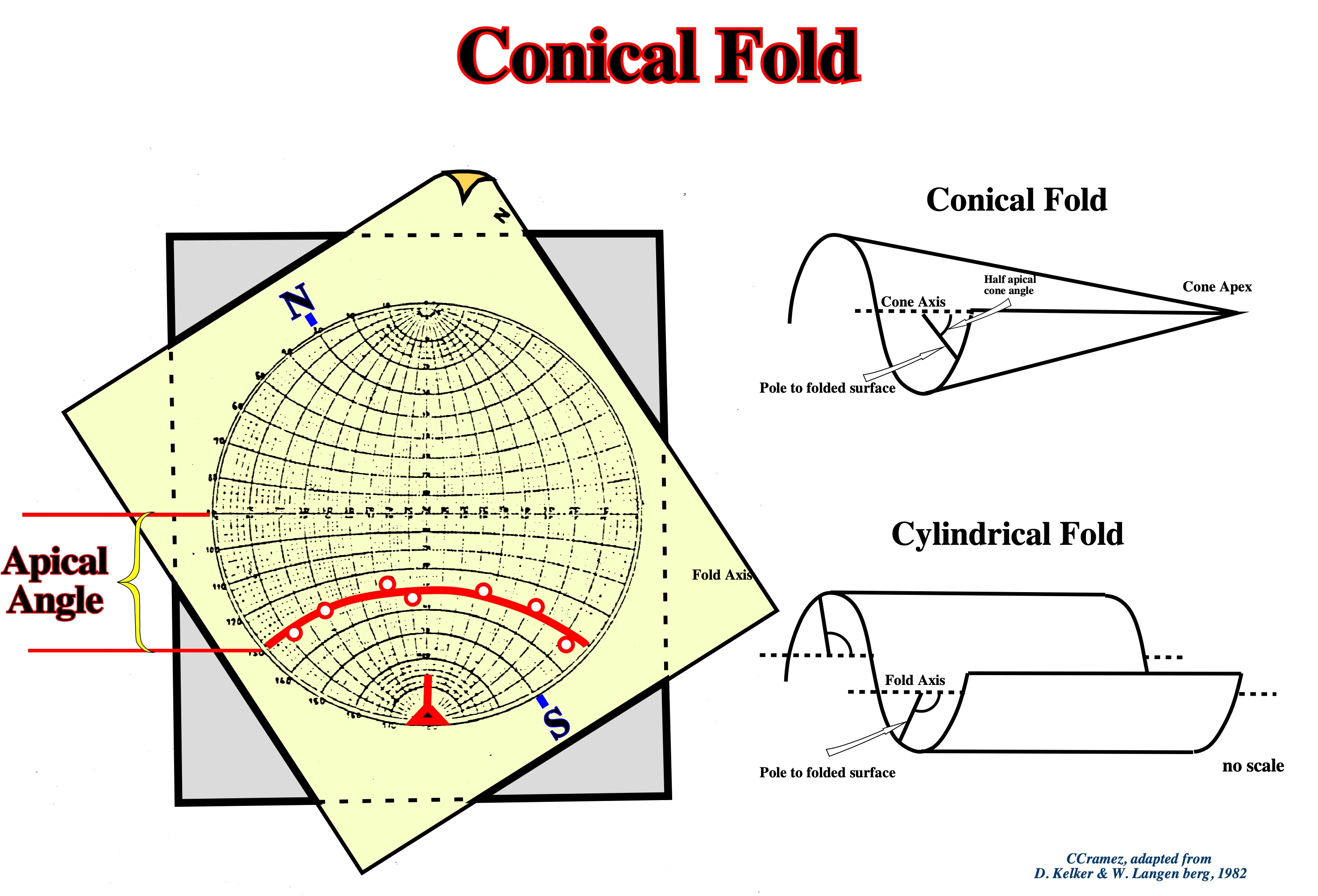
Conical anticlines, generally, associated with strike slip movements, are oblique top the maximum effective stress. In stereographic projection, their flanks lie on a parallel. The apical angle, as illustrated above, is the angle between the equatorial parallel and the parallel where the anticline flanks lie.
Fold Hinge
The line connecting the points of flexure or maximum curvature of the bedding planes in a fold. Synonym of hinge line.
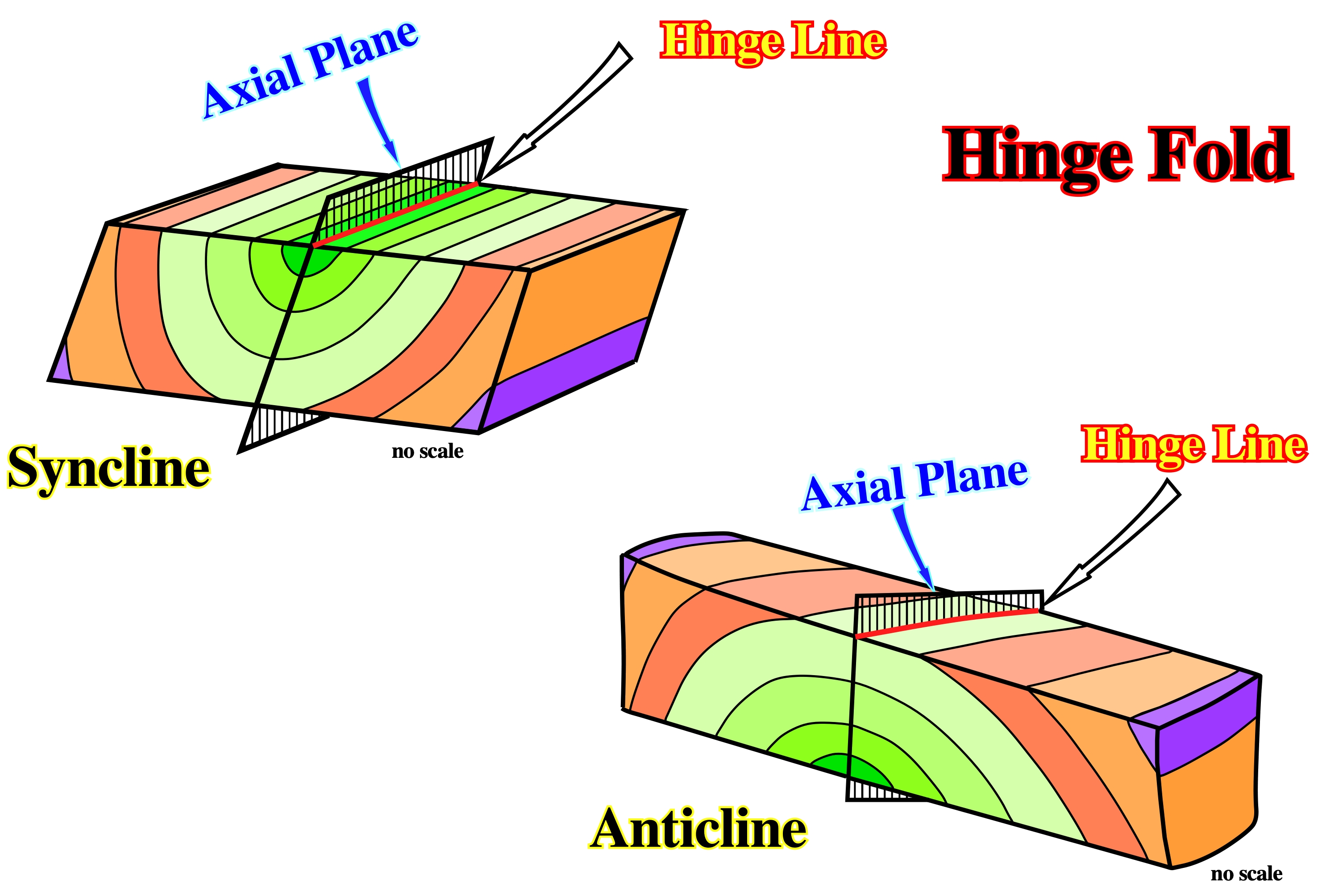
The hinge line of a fold (anticline or syncline) can be easily determined. It is given by the intersection of the axial plane, where lies the medium effective stress (σ2), with the horizontal plane. The dip of the hinge line gives the inclination of the axis of the structure.
Fold-Belt
Synonym of Orogenic belt.
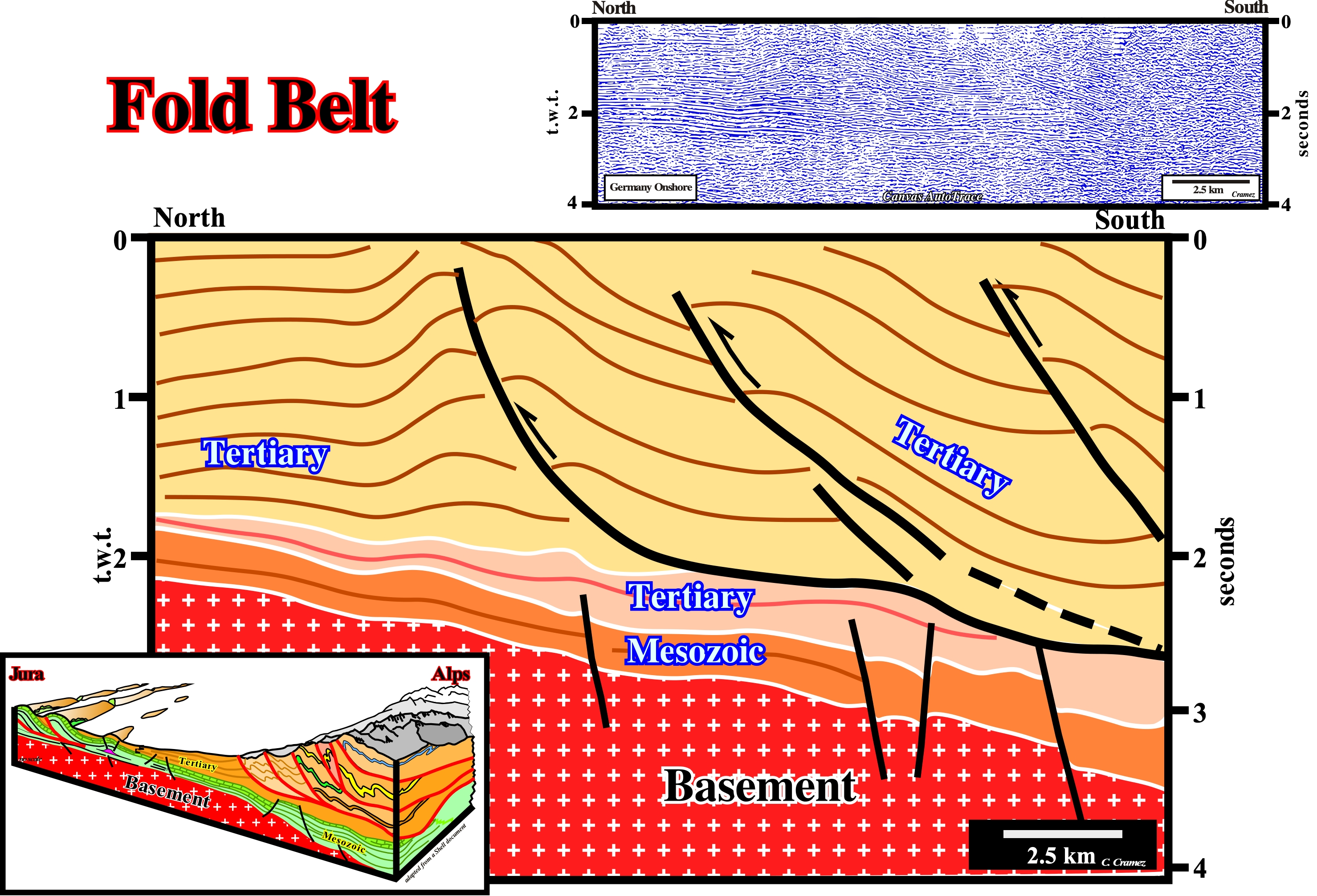
A fold belt is a chain of mountains formed during a Wilson's cycle, whose tectono-stratigraphic phases are: (i) Stable Continental Craton ; (2) Thermal anomaly (hot spot) and Lengthening (rifting), which induces the formation of rift-type basins (usually halfgrabens with opposite vergence on each side of the thermal anomaly) ; (3) Breakup of the Lithosphere, with creation of new oceanic crust and formation of two divergent margins ; (4) Sea-floor Spreading (oceanic expansion) that gradually transforms the young margins into mature margins due to the cooling and increasing density of the oceanic crust ; (5) Subduction, as the density of the oceanic crust becomes higher, it is divided into two parts and one of them enters in subduction (plunges under the other) creating a convergent margin, forming a volcanic arc and uplift of a mountain range on the overriding lithospheric plate ; (6) Divergent Margin/Volcanic Arc Collision with formation of a mountain range ; (7) Peneplanation and new subduction of the oceanic crust with the twin margin creating another convergent margin ; (8) Continent/Continent Collision and closure of the ocean created between the two primeval divergent margins and (9) New stable continental craton. The main fold belts are associated with A-type subduction zones (Ampferer), in which the plunging lithospheric plate is continental in nature. Most of the time, the overriding lithospheric plate has, also, a continental nature. Most fold belts correspond to the closing of a sea or an ocean, located between two divergent continental margins. Over time, the oceanic crust formed in the early oceanization stages becomes, progressively, colder and more dense. From a given moment, the density contrast between the old oceanic crust and the adjacent continent (or even with recent oceanic crust) may be large enough for the ancient oceanic crust begin to plunge, either, directly, under continental crust or under a portion of oceanic crust adjacent to the mainland. From that moment on, the oceanic crust begins to be consumed along the subduction zone, which implies, progressively, a decrease in the volume of the ocean basin between the two continents and, thus, the progressive closure of the sea or ocean between them. Since the continents collide (continental crust against continental crustal), the sea, between them, disappears and the sediments are shortened and uplifted into a mountain range, as illustrated in this tentative interpretation of a Canvas autotrace of a German onshore seismic line. On this tentative interpretation, as in the diagram block, it is easy to see that the northern margin of the Tethys Sea went into subduction under the southern margin causing a significant shortening of the sediments that is represented here by the Alps mountains, where the thrust faults and the tectonic nappes are predominant. On the contrary, on the north margin, here represented by the Jura mountains, not only is the basement involved in the deformation, but the thrusts are, practically, absent.
Footwall
The underlying side of a fault, ore-body, or mine working. Also, the wall rock beneath an inclined vein or fault.
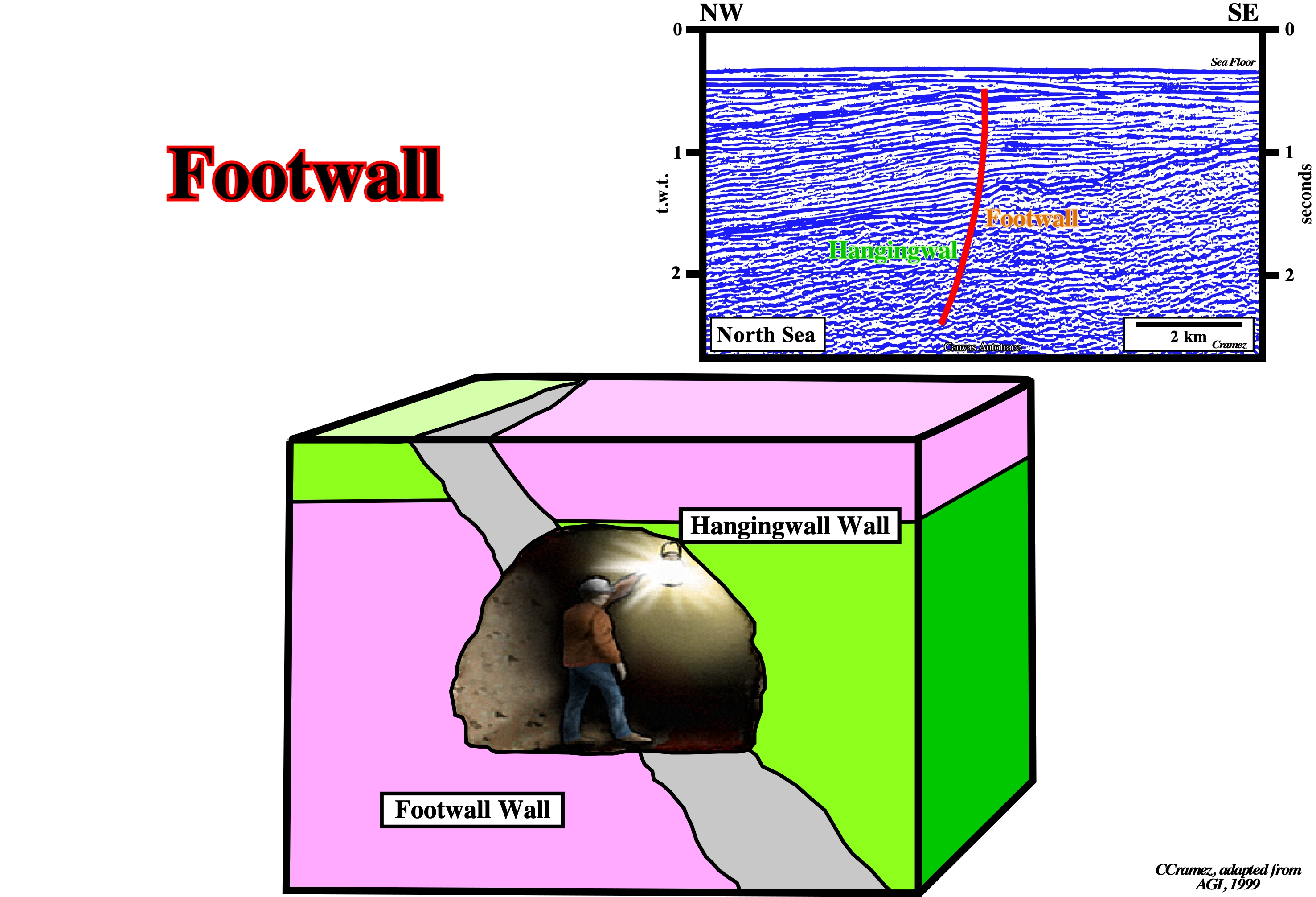
Initially, the term footwall was, mainly, used by the mining workers before being adopted by the American Petroleum Geologists. It corresponds to the up-thrown faulted block of the French geologists.
Foredeep Basin (Bally and Snelson, 1980)
Basin associated with the formation of the megasutures and located in the plunging continental lithospheric plate. Foredeep basins are often related with an Ampferer subduction zone.
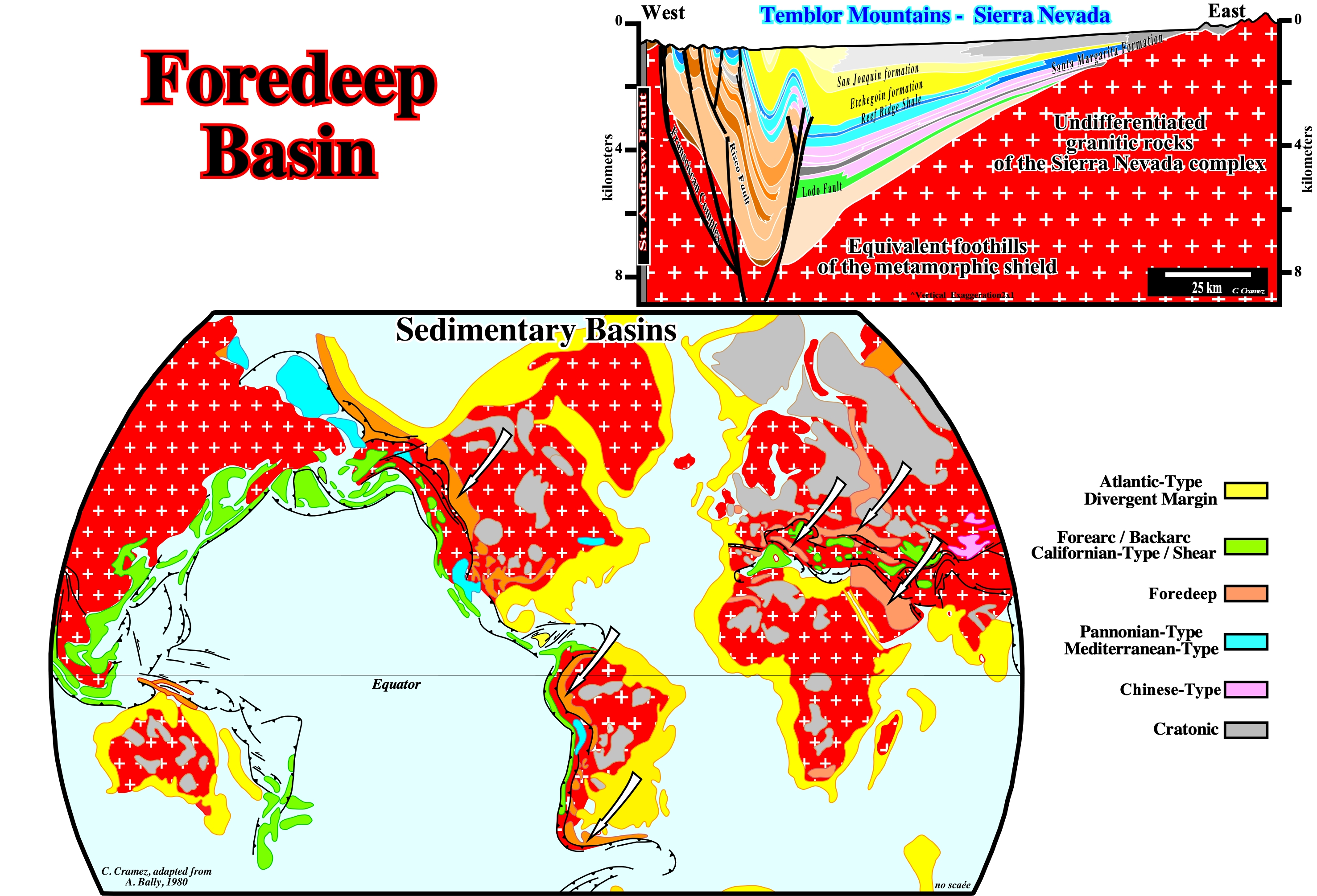
Foredeep basins are associated with the formation of the megasutures and particularly with the Ampferer, or A-type, subduction zones, where a continental lithospheric plate sink under a continental or oceanic thrusting plate.
Fore-Raft
Structures deposited above the upper compartments of major basement faults or quite close to the noses of the large tilted blocks when translation is taken into account. Fore-raft are characterized by the presence of erosional surfaces, steep dips and large salt pillows.
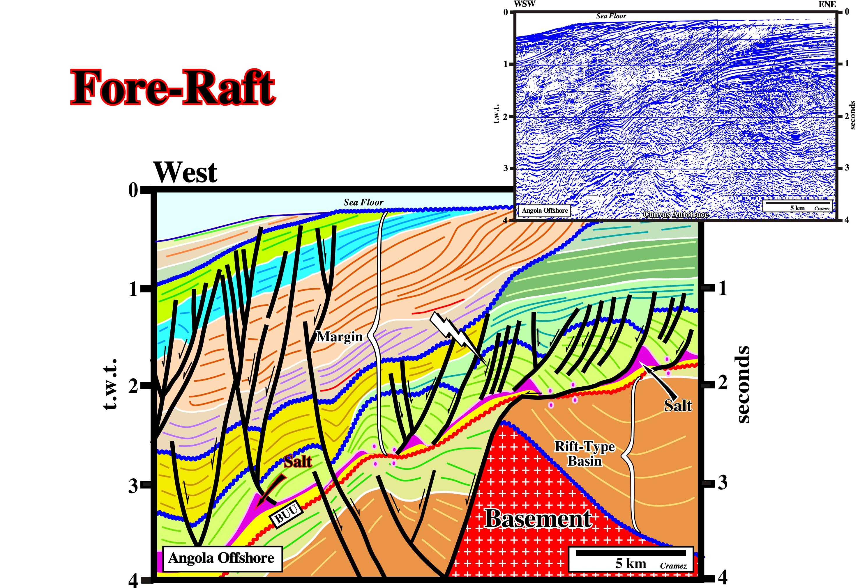
Fore-rafts structures, located in the basinward side of a raft, are located, slightly, down-dip of the basement (or subsalt strata) highs. In carbonate intervals, and contrariwise to back-rafts, they are very good potential reservoirs. In the area where this line was shot, there two main generating petroleum subsystems. A lower one, located in the rift-type basin (lacustrine shales) and an upper one, located in the overburden and associated with the Cretaceous major downlap surface (Cenomanian-Turonian). On this tentative interpretation the breakup unconformity (BUU), colored in red, is clearly recognized. It separated the rift-type basin sediments from the margins sediments. The basal sediments of the margin, i.e., the Cuvo sandstones (in yellow) are covered by the salt layer (Loeme formation) or by a salt weld. The bottom of the salt emphasizes a salt induced tectonic disharmony, since the cover (salt plus overburden) is partially, affected by the halokinesis. The toplaps at the sea floor are due to the Late Tertiary uplift of the Angola conventional offshore and onshore, that lengthened and tilted seaward the upper margin sediments, i.e., the uplift was induced by a more or less regional extensional tectonic regime rather induced by a compressional tectonic regime.
Forestepping
The geometry associated with the regressive intervals, where the successive depositional coastal breaks and/or shelf breaks are, progressively, displaced seaward. In the onset of a regressive episode, the basin has a platform, and so, depositional coastal breaks and shelf breaks can be recognized. However, after a certain amount of forestepping, the basins has no more platform and the depositional coastal break and shelf break are coincident.
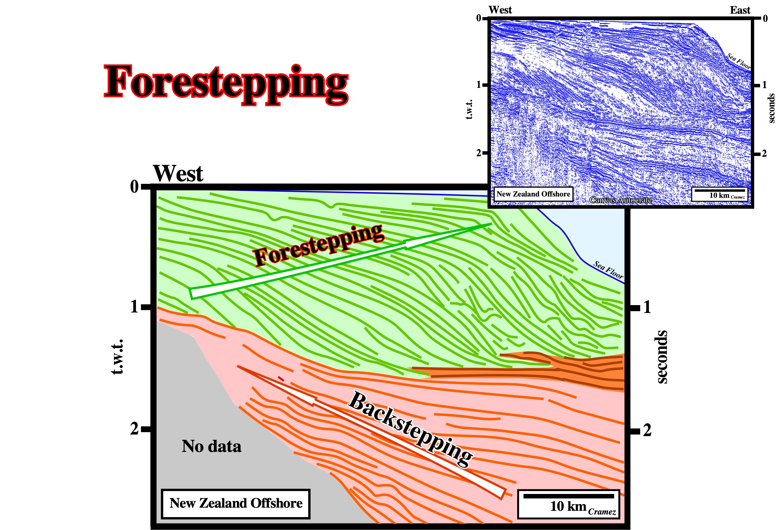
The upper sedimentary package overlying the major downlap surface is, mainly, composed by a succession of regressive episodes separated by minor transgressive or retrogradational episodes. Globally, the geometry of shelf breaks is mainly forestepping, since they have been, almost continually, displaced seaward.
Forward Molding Models
See: Molding and Backward molding models.
In forward molding models, the selection process start with an empty model and variables are added sequentially. In backward selection, the selection process is started with the full model and variables are excluded sequentially.
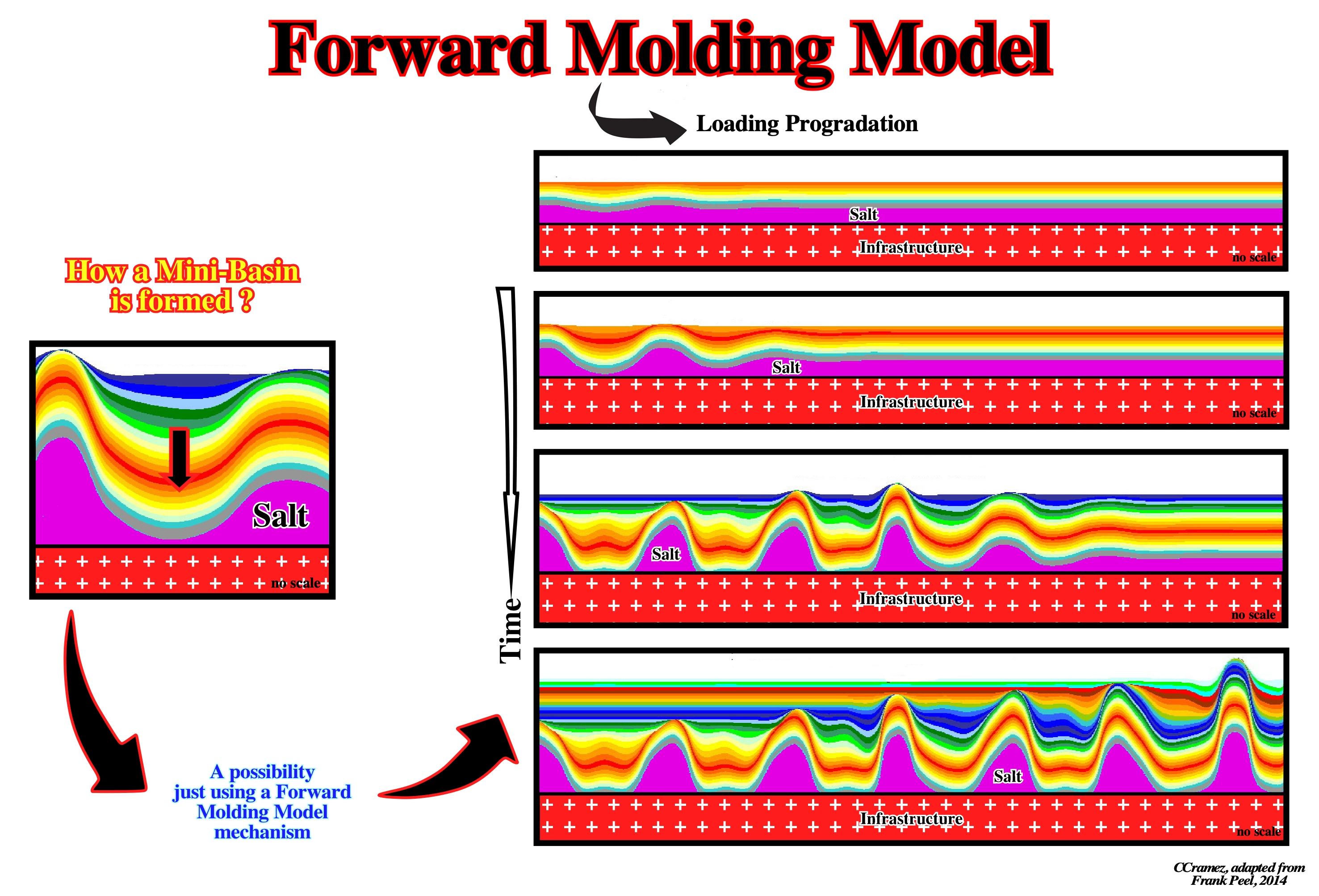
Some geoscientists believe "forward-backward" selection is another name for "forward-stepwise" selection (https://stats .stackexchange.com/ questions/277132/ forward-backward-model-selection-what-is-the-starting-model). This is the default approach used by stepAIC (AIC stands for Akaike Information Criteria.). In this procedure, you start with an empty model and build up sequentially just like in forward selection. The only caveat is that every time you add a new variable, Xnew, you have to check to see if any of the other variables that are already in the model should be dropped after Xnew is included. In this approach, you can end up searching "nonlinearly" through all the different models.
Fracture Zone
Zone of fragility of the continental crust, which can favor the breakup of the lithosphere. In offshore, and particularly in the divergent Atlantic-type margins, fracture zones are often directly, or indirectly, associated with transform faults and changes in the rate of sea floor spreading.
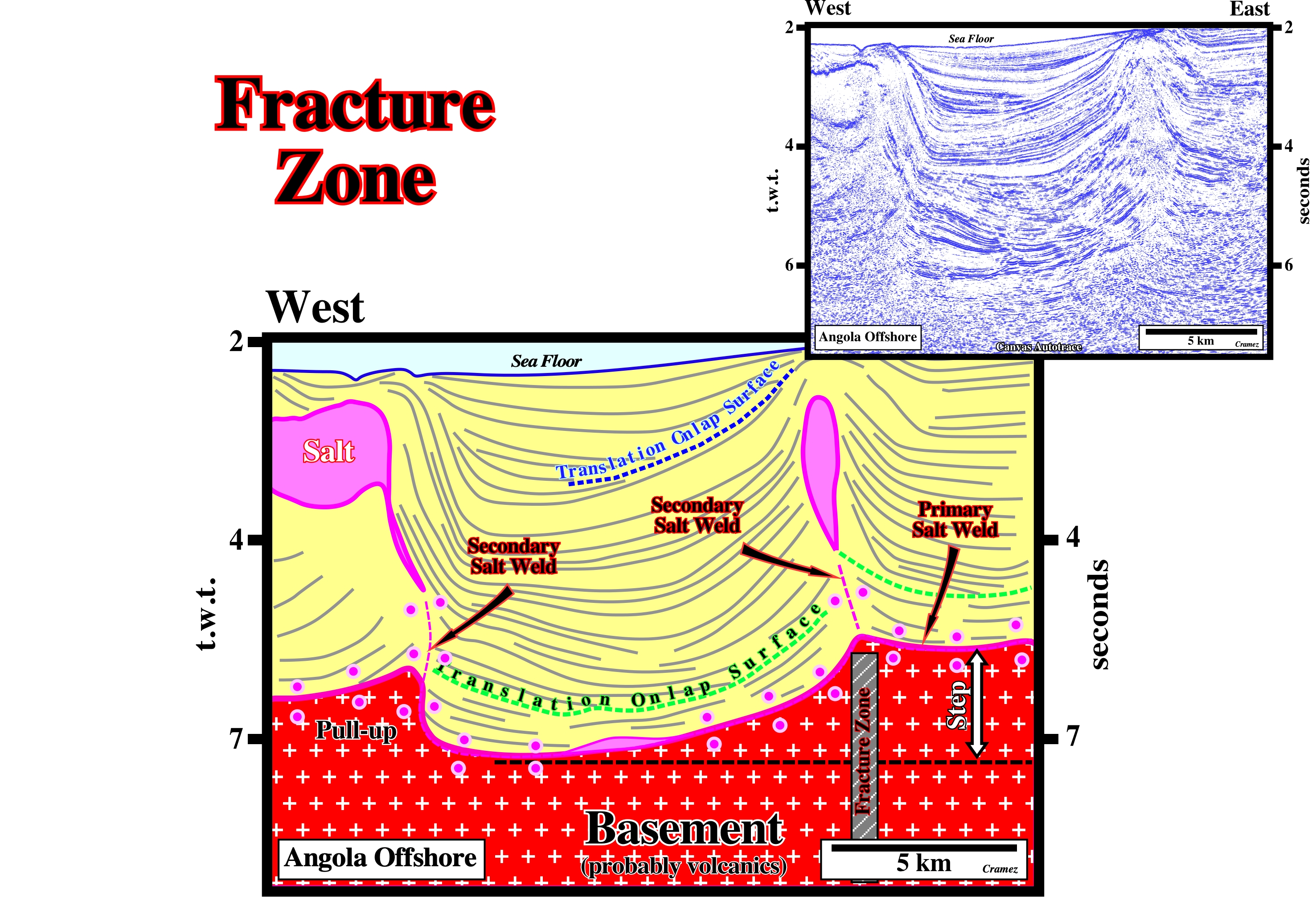
In offshore Angola, from where this Canvas autotrace comes, some fracture zones correspond to reactivated pre-Pangea fractures or rifting faults. The firsts strike roughly WE-SW, the others are oriented more or less North-South. The fracture zones related with pre-Pangea are well recognized on the morphology of the shoreline of Angola, which is affected by extensional strike-slip faults playing as "piano keys". On this tentative interpretation, the lower translation onlap surface is associated with the salt step induced by the fracture zone. Note the pull-up of the primary salt weld in the western part of the tentative interpretation induced by the allochthonous salt.
Freeboard
The height of the crest of a salt diapir or sheet above the surrounding sediment surface.
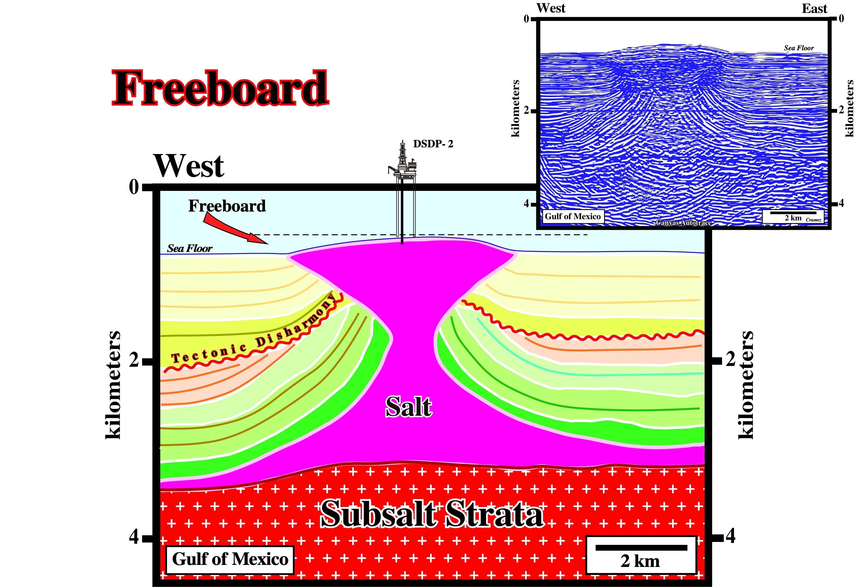
The freeboard of the Green Knoll structure (Gulf of Mexico) is quite well marked on the morphology of the bottom sea. The freeboard of extrusive salt diapirs or allochthonous sheet are easily recognized on dip maps of the bottom of the sea. This salt structure is located in the northern Gulf of Mexico at approximately 90° 20'W, 20° N. It is asymmetrical in shape, being 13.8 km in length and 9 in width, and its physiographic expression on the sea floor constitutes 136.5 meters of relief (A.M. Swiercy, chapter10 of Handbook of Geophysical Exploration at Sea, 2nd Edition, 1991).
Free Surface
Surface that perpendicularly to it the confining pressure is meaningless and along which deformation takes place. Uplift takes place perpendicularly to the free surface. The surface of the geoid can be considered as a free surface.
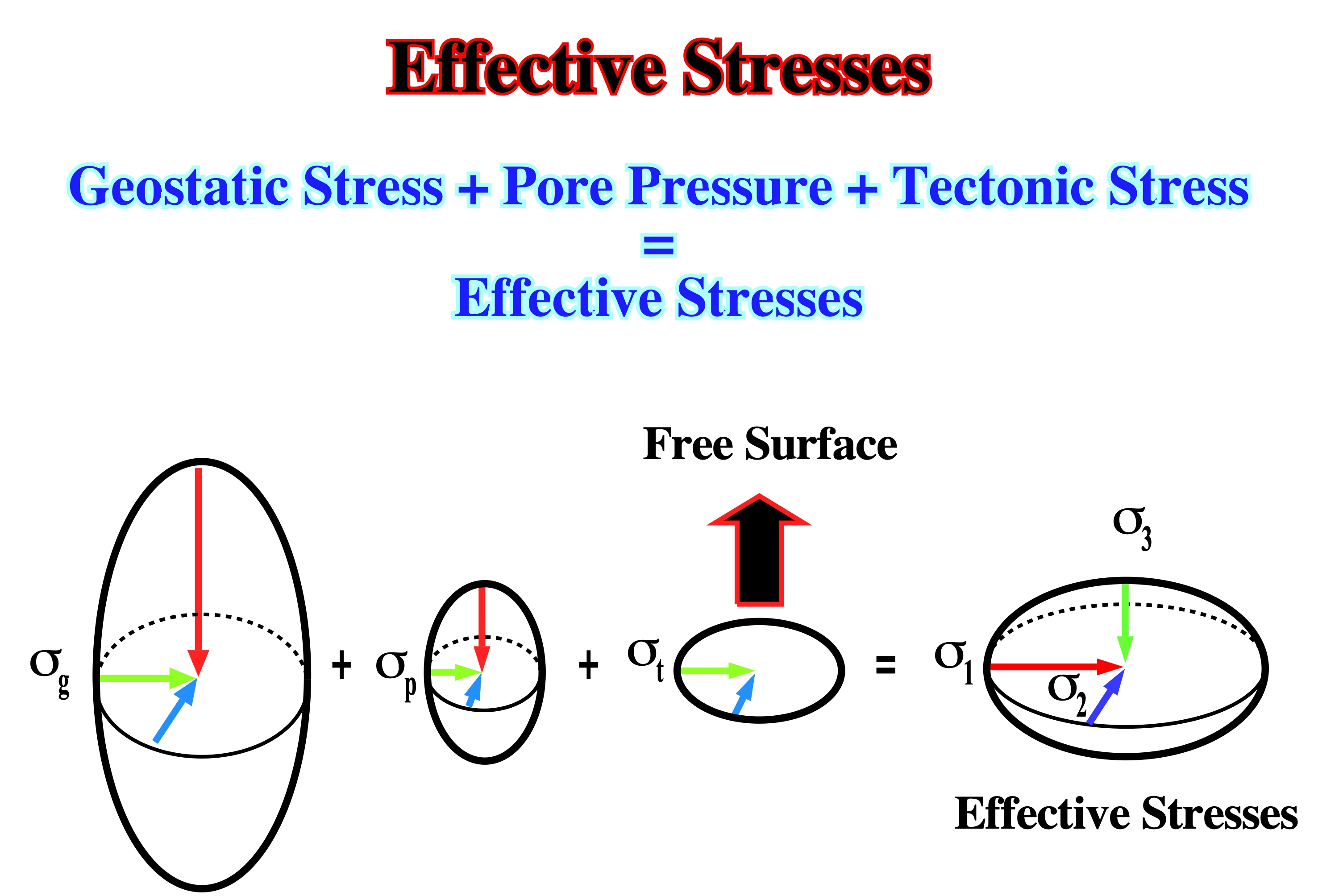
Earth's surface is the outward free surface, since perpendicular to it there is not confining pressure. The implications of such a features are well known. In areas characterized by a tectonic regime with a minimum effective stress vertical (cylindrical folds, reverse faults and thrusts), is not uncommon to see erroneous seismic interpretations with fault planes becoming subvertical in depth. Such a fault geometry (in the given tectonic regime) implies an inward free surface.
Friction
The force needed to keep one solid surface just sliding over another (kinetic or dynamic friction) or the force which has to be applied to initiate motion is slightly greater and is called static or limiting friction. The friction increases approximately in proportion to the total perpendicular force (normal reaction) between surfaces and its ratio to the normal reaction between the surfaces is called the coefficient of friction (m).
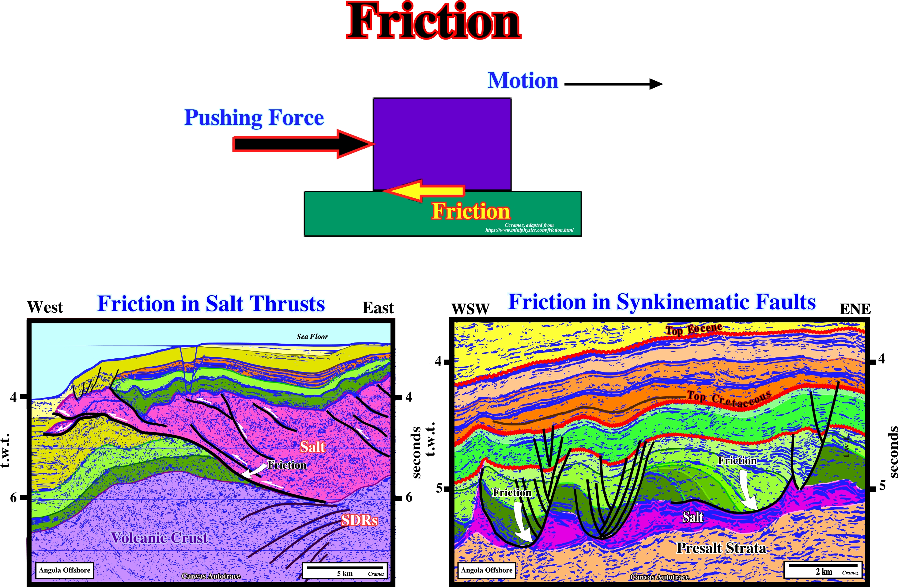
In salt tectonics as well as in halokinesis, friction is quite important not only at salt bottom (salt welds) but also in salt welds, salt thrusts and between salt and overburden sediments in synkinematic faults, as illustrated on the above tentative geological interpretations of Angola offshore Canvas autotraces.