
Radial Faults
Normal faultsm that, generally, radiate from a central point. They are created by an extensional tectonic regime (σ1 vertical), in which the horizontal axes of the effective stresses ellipsoid are equal. Radial fault are also named stretching faults.
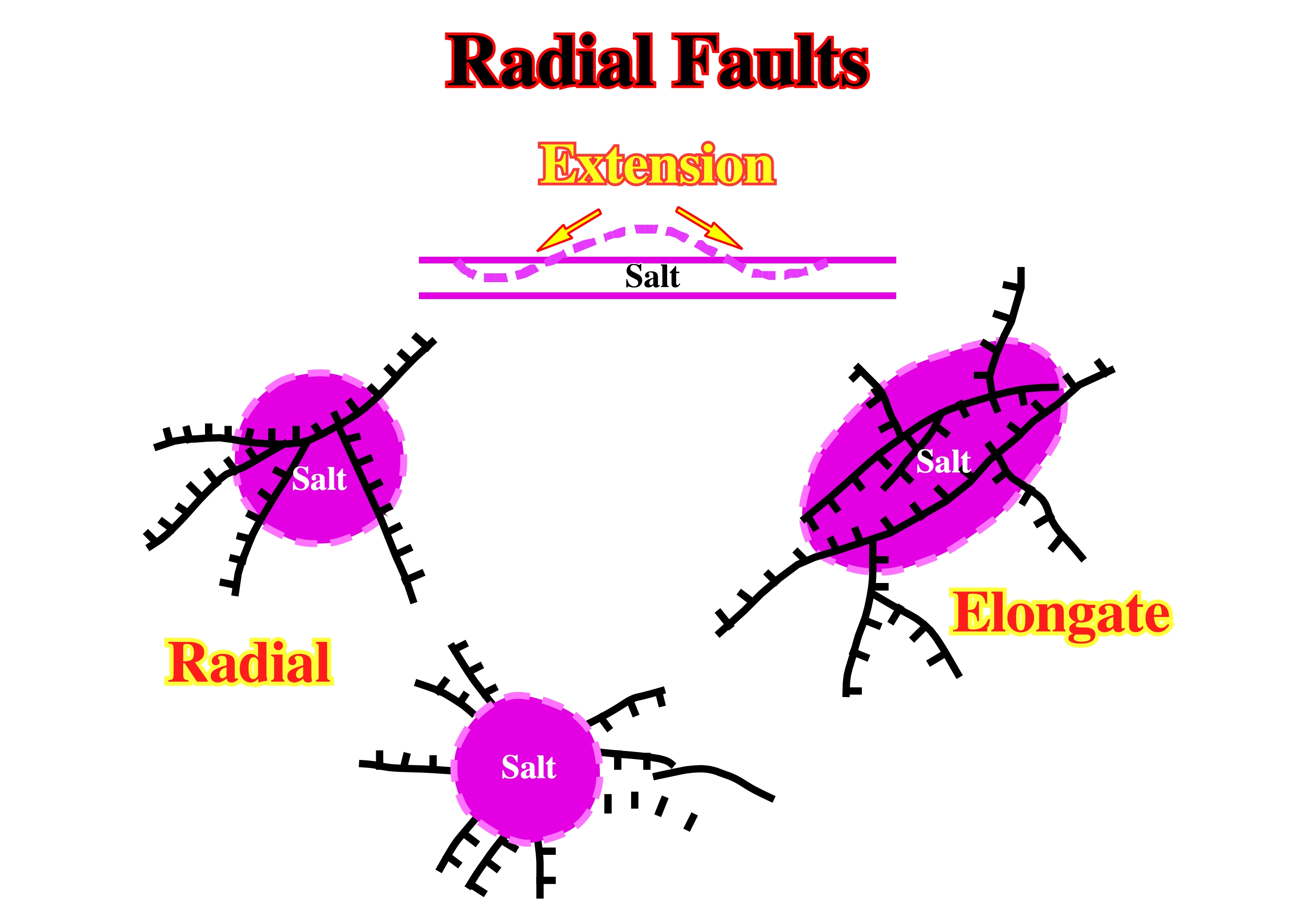
Radial faults are, mainly, associated with salt domes, shale domes and buried hills. The associated tectonic regime is characterized by a σ1 vertical (extension, lengthening) and σ2 = σ3, i.e., with a biaxial ellipsoid of effective stresses.
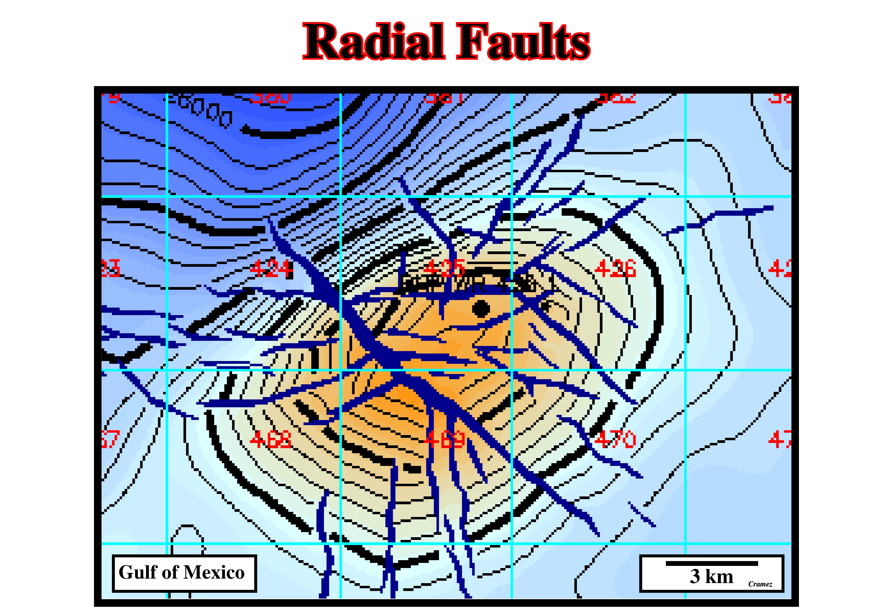
The radial faults recognized in the apex of this domal structure, strongly, suggest the sediments where lengthened which implies a late extensional tectonic regime. It is possible that a compressional tectonic regime shortened the sediments in a first phase, but it is quite evident that, later, an extensional regime, induced, probably, by a salt intrusion.
Raft
Fault block of allochthonous overburden that have separated to the extent that they no longer rest on their original footwall (the adjoining fault block) and lie, entirely, on a decollement layer, which typically consists of rock salt.
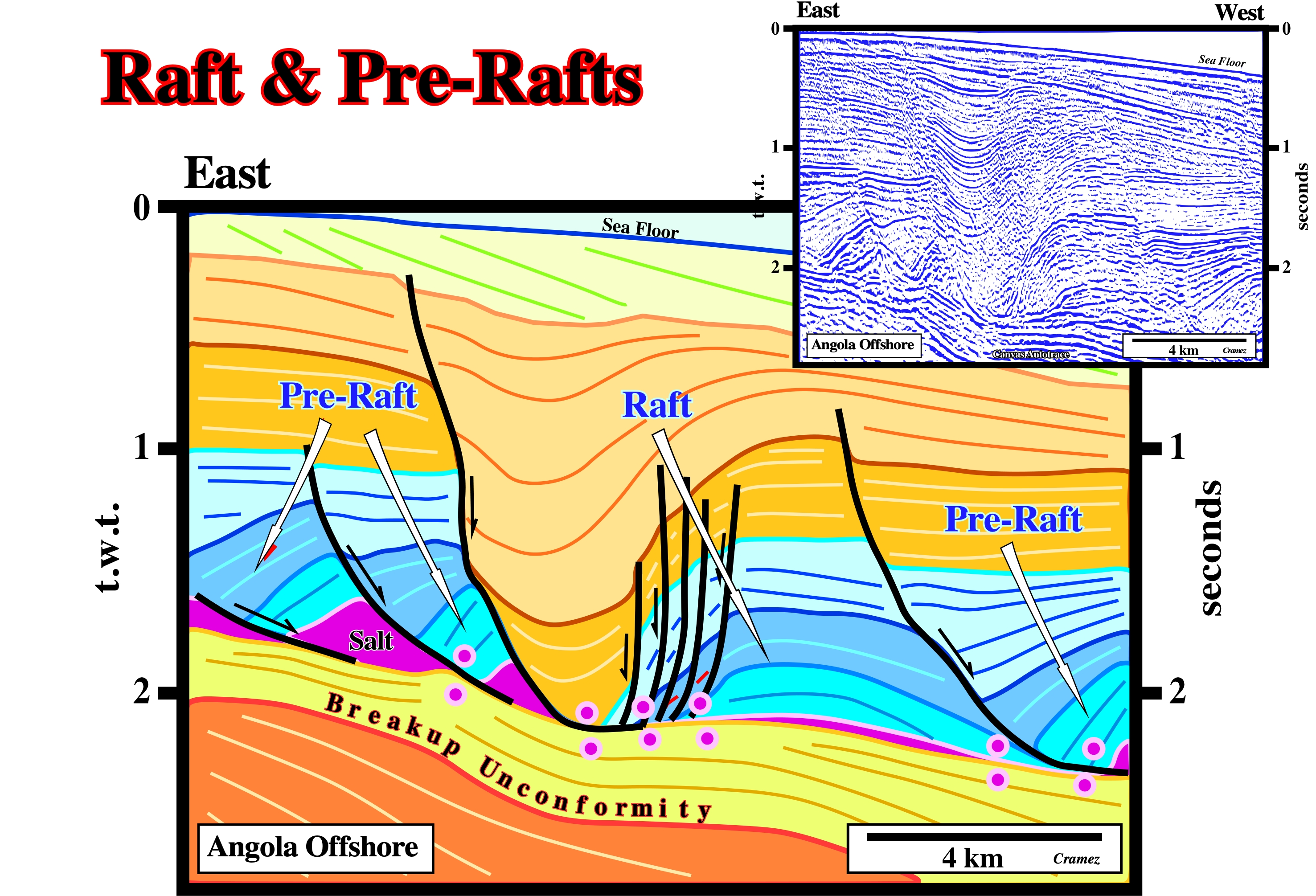
This tentative geological interpretation of a Canvas autotrace of an Angola offshore seismic line illustrates, clearly, the different between raft and pre-rafts. A salt weld and a thick depocenters induced by a local complete salt evacuation, separates two pre-rafts from a raft. Another pre-raft is recognized seaward. The tectonic disharmony underlining the bottom of the salt is so obvious that, in Angola, the bottom of the salt was, erroneously, considered as an unconformity and used to separate the stratigraphy into two major intervals: subsalt strata and post salt strata.
Raft Tectonics
Extreme extension characterized by the opening of synsedimentary deep grabens and separation of intervening overburden into rafts, which slide downslope on a decollement of thin salt, like a block-glide landslip.
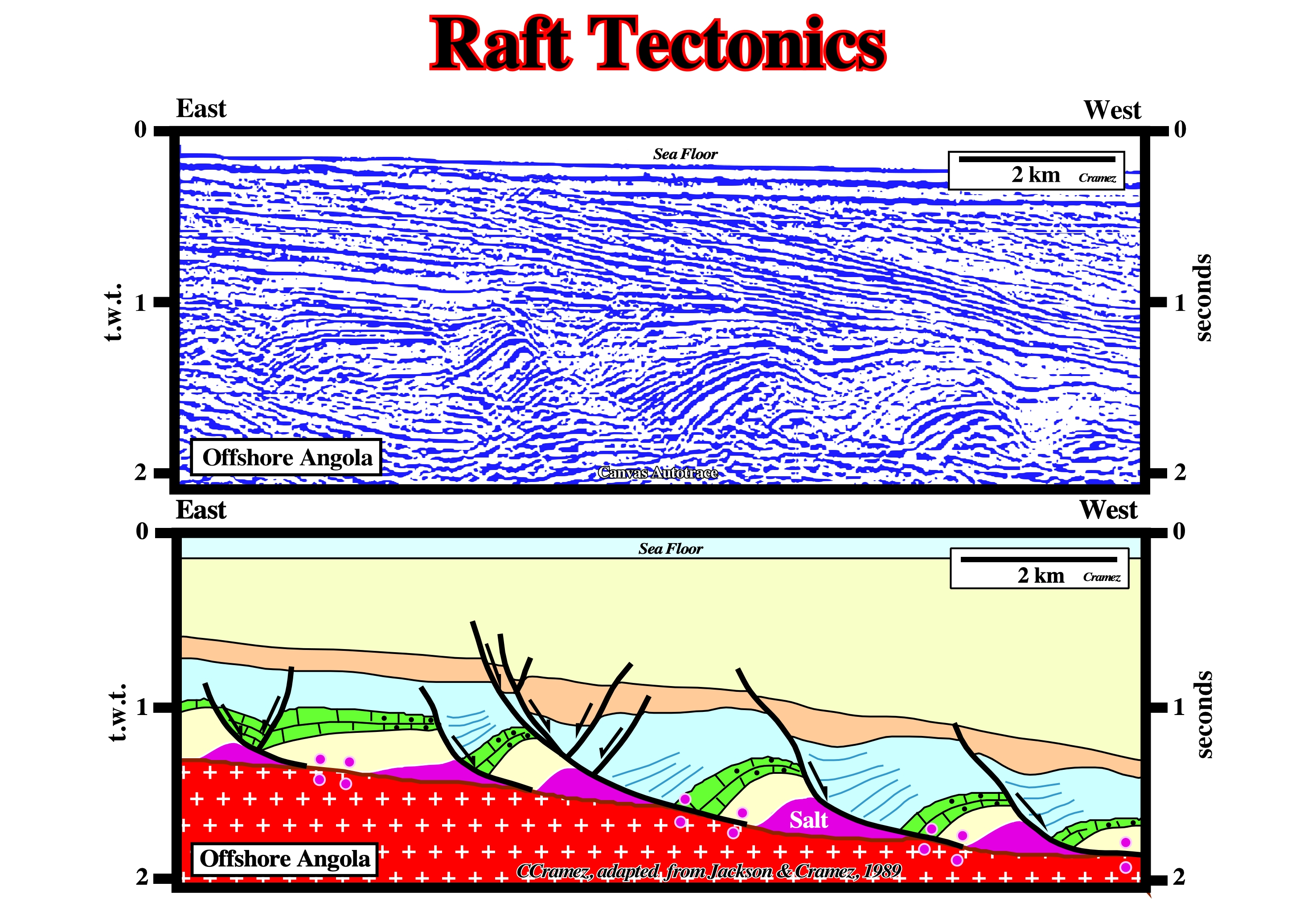
Raft Tectonics was first recognized in Angola onshore by Petrangol's geoscientists and then by geoscientists of CFP (today Total SA) who hypothesize gravity as the main driving mechanism ("Tectonique en Radeau", Burollet, P.F., 1975).
Ramp
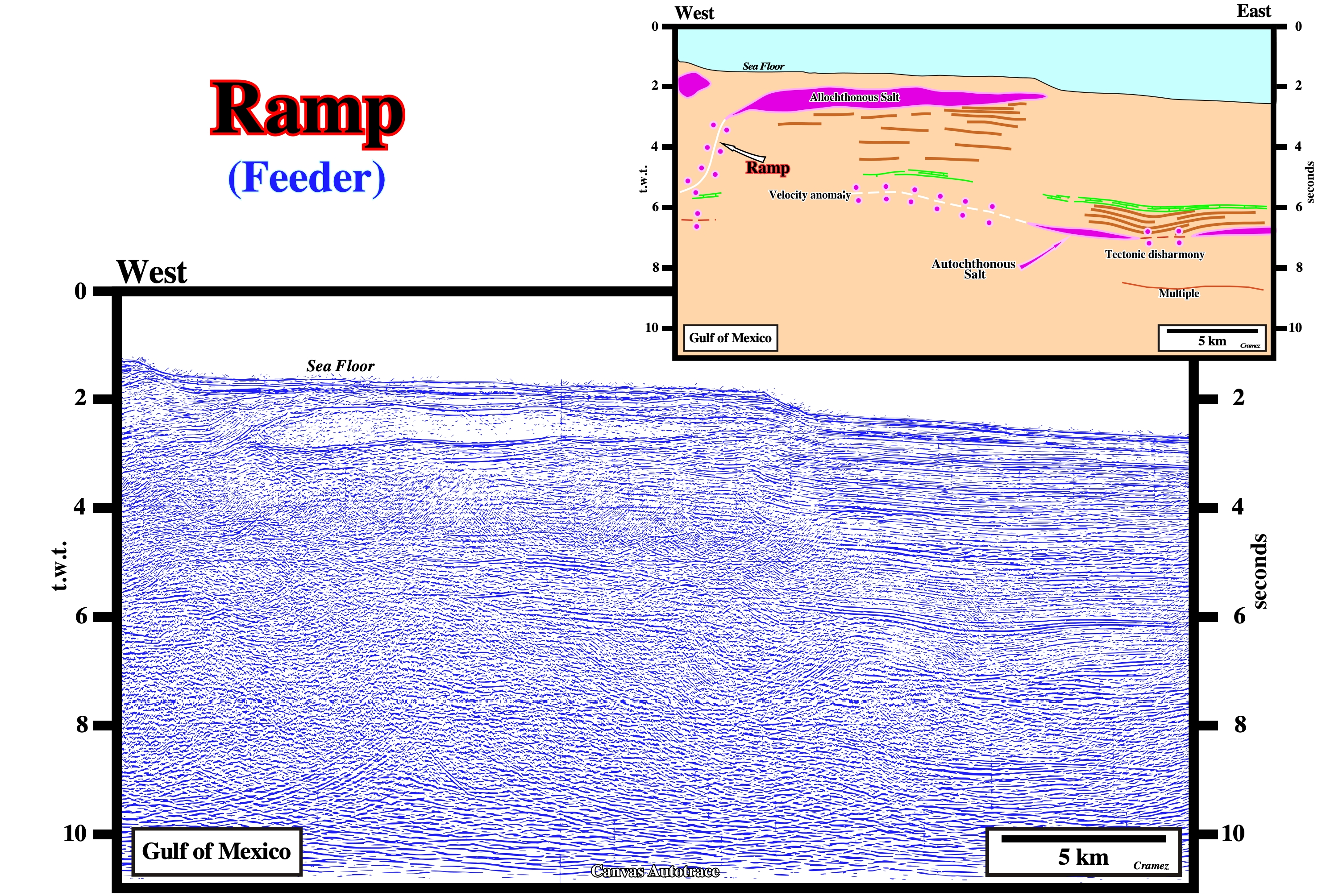
On this preliminary tentative geological interpretation of a Canvas autotrace of a Gulf of Mexico seismic line, a salt ramp between the autochthonous salt layer, represented mainly by a secondary salt weld, and the allochthonous salt is quite well visible on the upper right part of the autotrace. Note the pitfall (pull-up) below the salt tongue, as well as the tectonic disharmony at the base of the overburden (salt weld) and the cover (salt plus overburden).
Rate of Rise (Talbot, C. J., 1995)
The vertical flow rate of salt minus dissolution. The rate of rise is represented by R°.
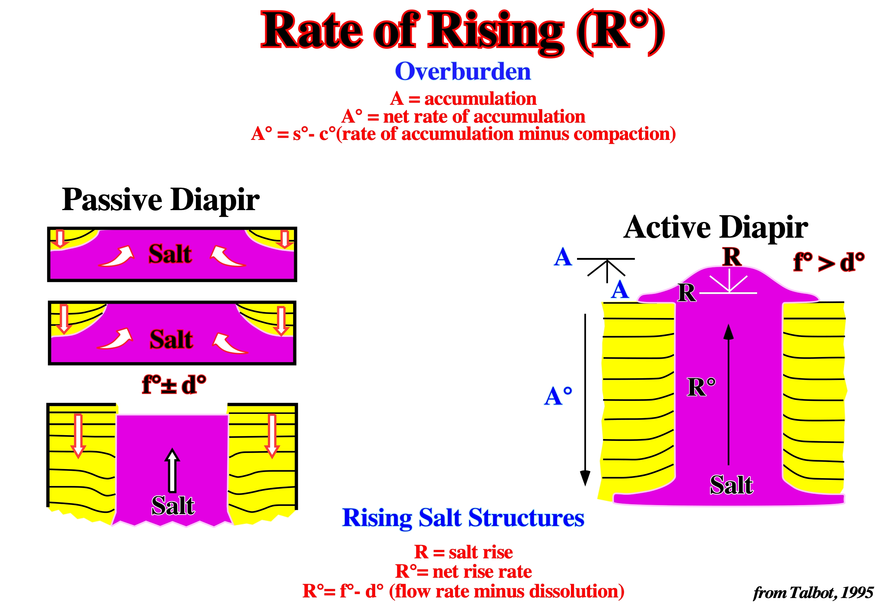
As illustrated above the net rate of rise of a salt diapir (R°) corresponds to the net flow rate (f°) minus the amount of dissolution (d°), while the net rate of accumulation rate of the overburden (A°) correspond to the rate of accumulation (s°) minus compaction (c°). Obviously, to calculate the rate of accumulation is indispensable to take into account the completeness, i.e., the relation between the effective time of deposition and total geological time. If the time between two consecutive unconformities is, for instance, 3.0 My and the effective deposition time is 1.0 My, the sedimentary completeness is 0.3. In turbidite systems, the completeness is quite small, but the preservation is quite great.
Rates of Geologic Processes
The following rates are the most relevant to salt tectonics: (i) Aggradation rate of overburden ; (ii) Dissolution rate of salt structure, (iii) Extension rate of overburden or salt ; (iv) Lateral injection rate of salt structure ; (iv) Progradation rate of overburden ; (v) Gross rate of salt flow upward ; (vi) Net rate of increase in relief of salt structure and (vii) Shortening rate of overburden or salt.
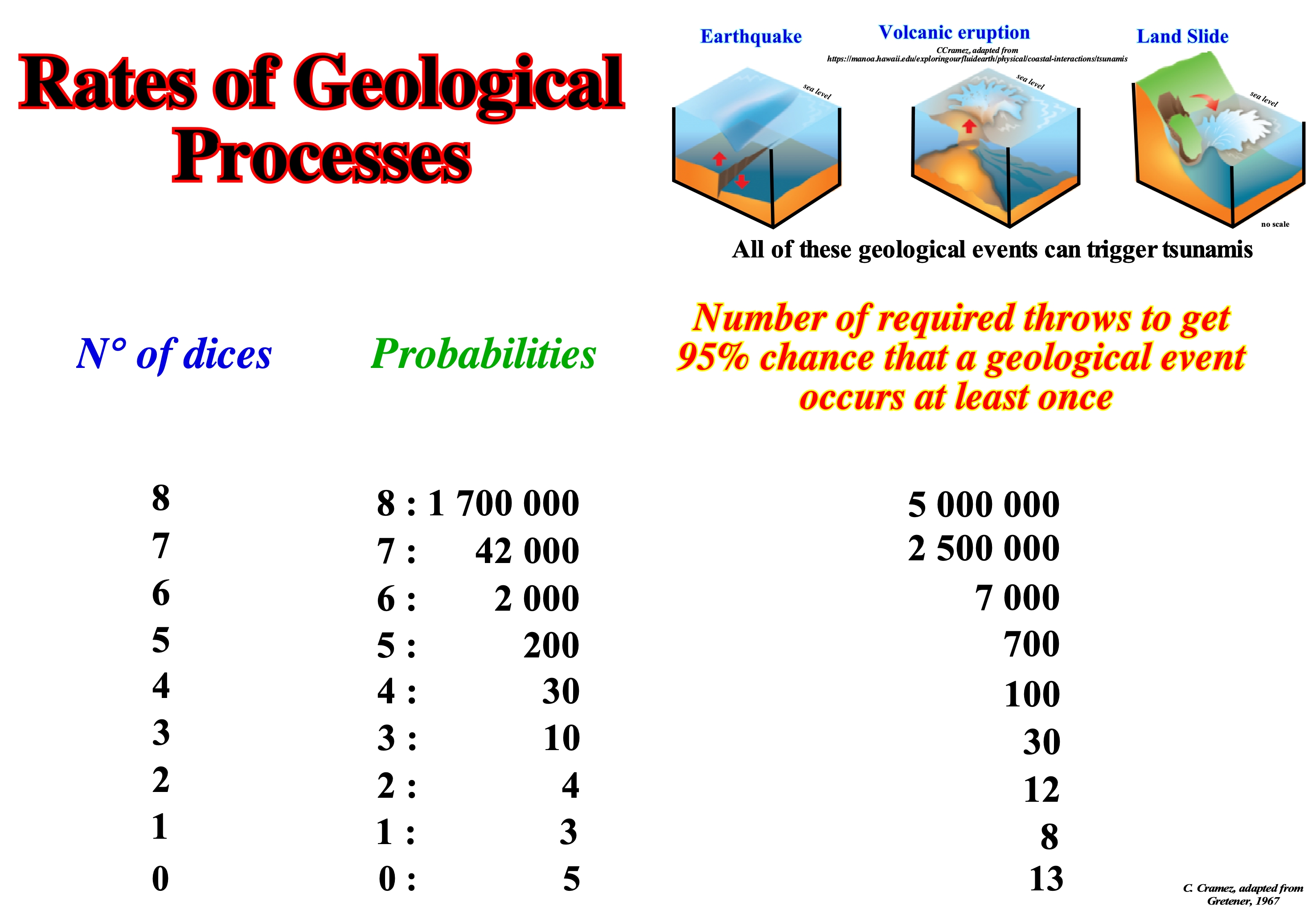
The rate of the geological processes can be approached by the concept of geological event, such as an earthquake, relative sea level rise (marine ingression), volcanic eruption or a landslide, which Gretener (1967) studied used a dice game. As a natural event depends, almost always, on the simultaneous occurrence of several factors, the probability of occurrence of such an event is the product of the probabilities of occurrence of the different factors. The formation of an oil accumulation, for instance, depends, mainly, on five parameters: (i) Source-Rock ; (ii) Trap ; (iii) Maturation of the organic matter of potential source-rock ; (iv) Age of migration of hydrocarbons in relation to age of trap formation and (v) Retention. The probability of discovering an oil accumulation (economic or otherwise) is the product of the probabilities of these five petroleum parameters. If the probability of a parameter is zero (0), the probability of discovery will be zero (0). If the parameter source-rock (presence and maturation of organic matter) is zero (0), i.e., if there is no source-rock in the region capable of generating hydrocarbons, the study of the other petroleum parameters is useless. This is why many geoscientists regard the source-rock parameter as a "killer parameter". In a game of octahedron dice game (its eight faces are triangles and are numbered 1 to 8), the probability of get 8 times the face 6, when all the dice (eight dice) are thrown is 1 in 2 x 10⁶ throws. However, as the number of throws increases, the probability of obtaining a throw with an eight-sided 6 increases, too. Theoretically, as illustrated in this figure, there is a 95% probability of obtaining, at least once, eight (8) faces with the number six in a total of about 5 million throws and 95% of probability of not obtaining at least one time, no face with number six in 13 throws. All this means that: (i) At the human scale (2-3 generations time), a small probability of occurrence of a certain geological event is considered as an impossibility, although there is no natural law that prevents this event from happening and (ii) What is, practically, impossible, at human scale (a collision of an asteroid with the Earth, for example) is just unlikely at the geological scale. In order to understand the meaning and importance of a geological event, it is, equally, important not to forget that a stratigraphic system, such as Silurian, is occasional and incomplete. It has numerous gaps (periods without deposition or erosion). In general, stratigraphic systems do not translate the equivalent geologic time interval, but just the time during which deposition occurred. The sedimentary completeness of a stratigraphic interval, which certain geoscientists call sedimentary integrity (ratio of actual deposition time to total interval time) and the preservation of a deposit are important elements. All geoscientists know that the sedimentary completeness of a turbidite layer is, more or less, 1, while that of a pelagic clay is largely higher than 1. A beach lamination deposit is deposited, more or less, in a second. A hummocky cross stratified layer (HCS layer), characteristic of storm deposits, is deposited in a few minutes. A turbidite layer deposits in a few hours. Flood deposits, such as the Canadian Scablands (deposits and erosions associated with flooding caused by the rupture of the retention of lakes located behind Pliocene-Pleistocene glaciers), are deposited in a few weeks. The glacial varves deposit in a year. One centimeter of pelagic sediments is deposited in about 103 years. A continental encroachment sub-cycle deposits between 10 - 20 x 106 years. A continental encroachment cycle is deposited at 100 - 200 x 106 years. Imagine a stratigraphic interval composed of 100 layers of turbidite and pelagic clay, where each turbidite layer has a thickness of 10 cm and each pelagic layer has a thickness of 5 cm. The total thickness will be 1,500 cm. Since the mean deposition velocity of the pelagic clays is about 5 cm/1000 years and the turbiditic currents are instantaneous stratigraphic events, we can say: (i) The total deposition time is 100 ky ; (ii) The frequency of the turbidite currents is 1 ky ; (iii) Two-thirds of the sedimentary interval was deposited by instantaneous events whose frequency is one event per thousand years ; (iv) In 10 Ma, 10,000 geologically instantaneous events can deposit a 1,500 m thick section.
Rayleigh-Taylor Instability
The hypothesis that a dense fluid overburden having negligible yield strength sinks into a less dense fluid salt layer, displacing it upward. A layer of viscous fluid of uniform density overlying a compositionally less-dense layer is unstable. Small perturbations in the horizontal interface become amplified at a rate, represented by an eigenvalue (the special value variable parameter for which the solution of an equation is nontrivial) that depends on the thickness, density, and viscosity of every layer, size of initial perturbation, and time elapse.
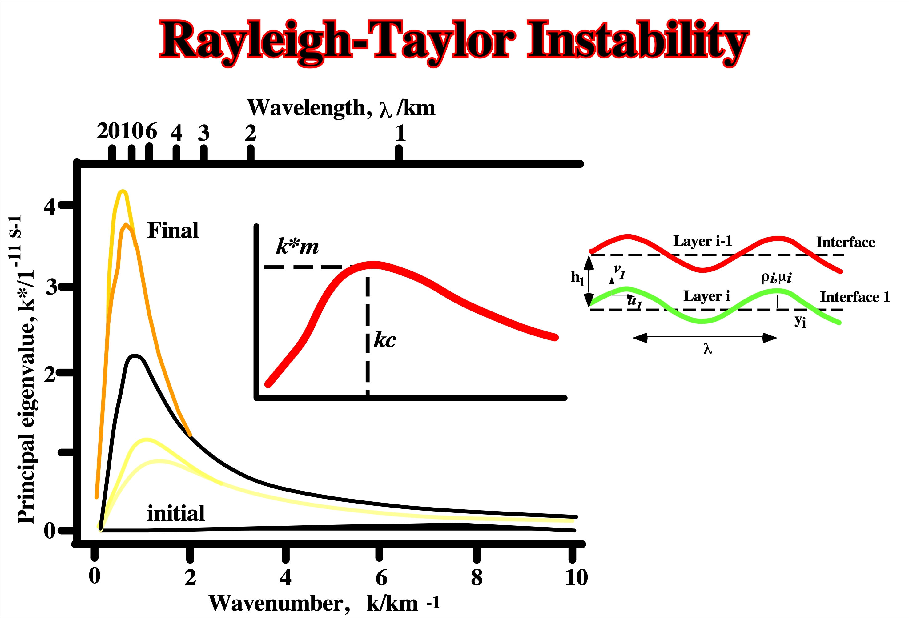
The Rayleigh-Taylor instability, i.e., the hypothesis that a dense fluid having negligible yield strength sinks into a less dense fluid salt layer, displacing it upward, dominate the fluid era of salt tectonics between 1933 and 1898.
Rayleigh-Taylor Number (Rt) (M. P. A. Jackson & Talbot, C. J., 1995)
A non-dimensional number for measuring the vigour of the Raleigh-Taylor instability and its capacity to advert heat. No critical Rt number exists below which the system is stable: Rt = δρ g h3 /kn, where δρ is the density contrast at the interface, g is the gravitational acceleration, k is the thermal diffusivity and n is the shear viscosity.
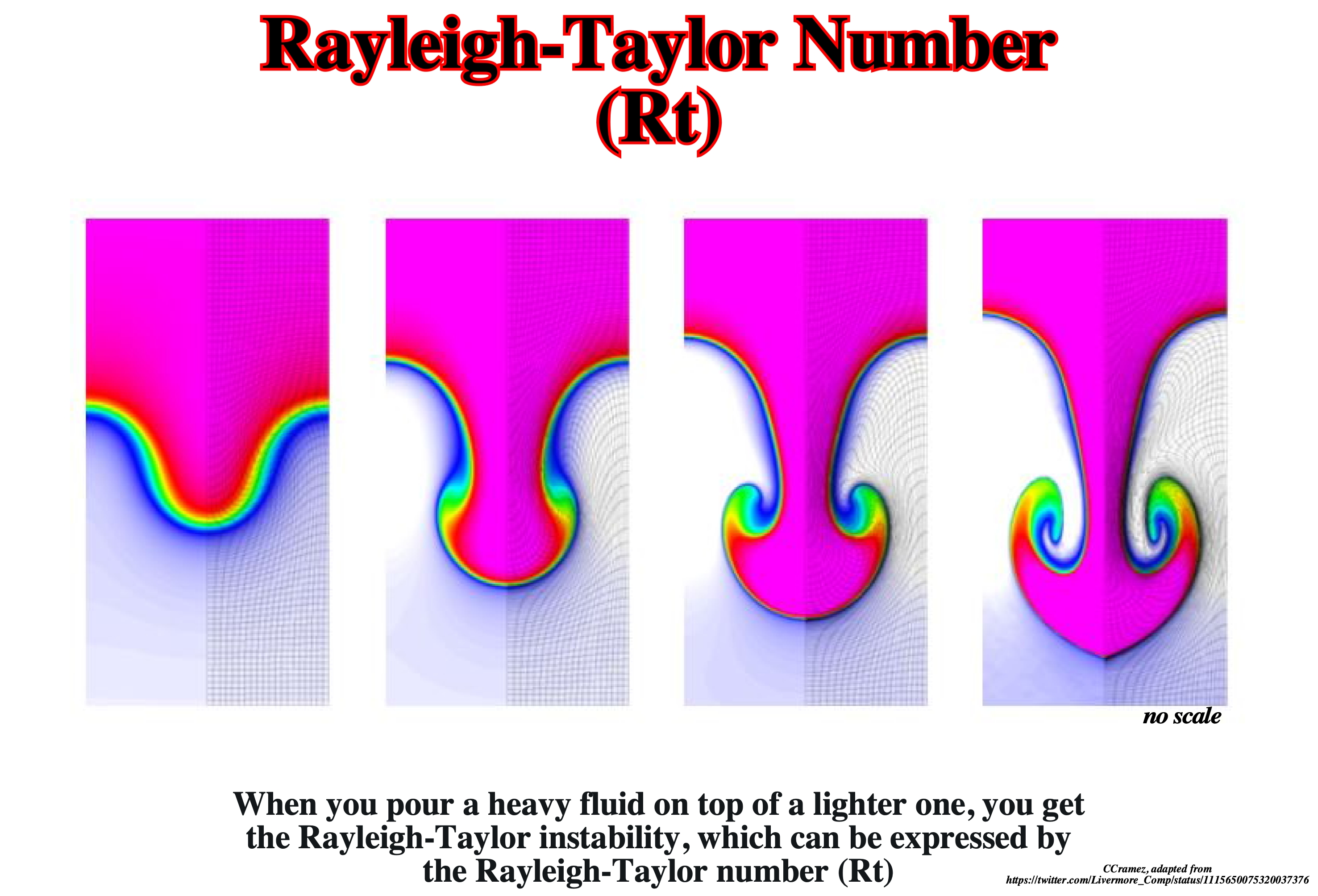
Considering the classic Rayleigh-Taylor instability problem which consists of a heavy fluid resting on top of a light fluid in a gravitational field supported by a counterbalancing pressure gradient, is illustrated above the results for density and curvilinear mesh in the Rayleigh-Taylor problem using Q1-Q0 finite elements at times t = 5. As time increases and the problem develops more vorticity, the low order methods begin to lock-up and are no longer able to resolve the flow as the mesh begins to tangle. As the order of the method is increased, the problem is able to run further in time and resolve more of the flow features while maintaining robustness in the Lagrangian mesh (lead to highly distorted elements around the corner, which in turn result in spurious oscillations of the relative density distribution). As the RT instability develops, the initial perturbations progress from a linear growth phase into a non-linear growth phase, eventually developing "plumes" flowing upwards (in the gravitational buoyancy sense) and "spikes" falling downwards. This phenomenon is observed in several common situations, not only in the salt domes or the inversion layers, but also in astrophysics and electrokinetics. In the linear phase, the fluid movement can be closely approximated by linear equations, and the amplitude of perturbations is growing exponentially with time. In the non-linear phase, perturbation amplitude is too large for a linear approximation, and non-linear equations are required to describe fluid motions. In general, the density disparity between the fluids determines the structure of the subsequent non-linear RT instability flows (assuming other variables such as surface tension and viscosity are negligible here). The difference in the fluid densities divided by their sum is defined as the Atwood number A. For A close to 0, RT instability flows take the form of symmetric "fingers" of fluid; for A close to 1, the much lighter fluid "below" the heavier fluid takes the form of larger bubble-like plumes.
Reactivated Salt Dome
Term generally used to designate a salt dome developed from an allochthonous salt layer.
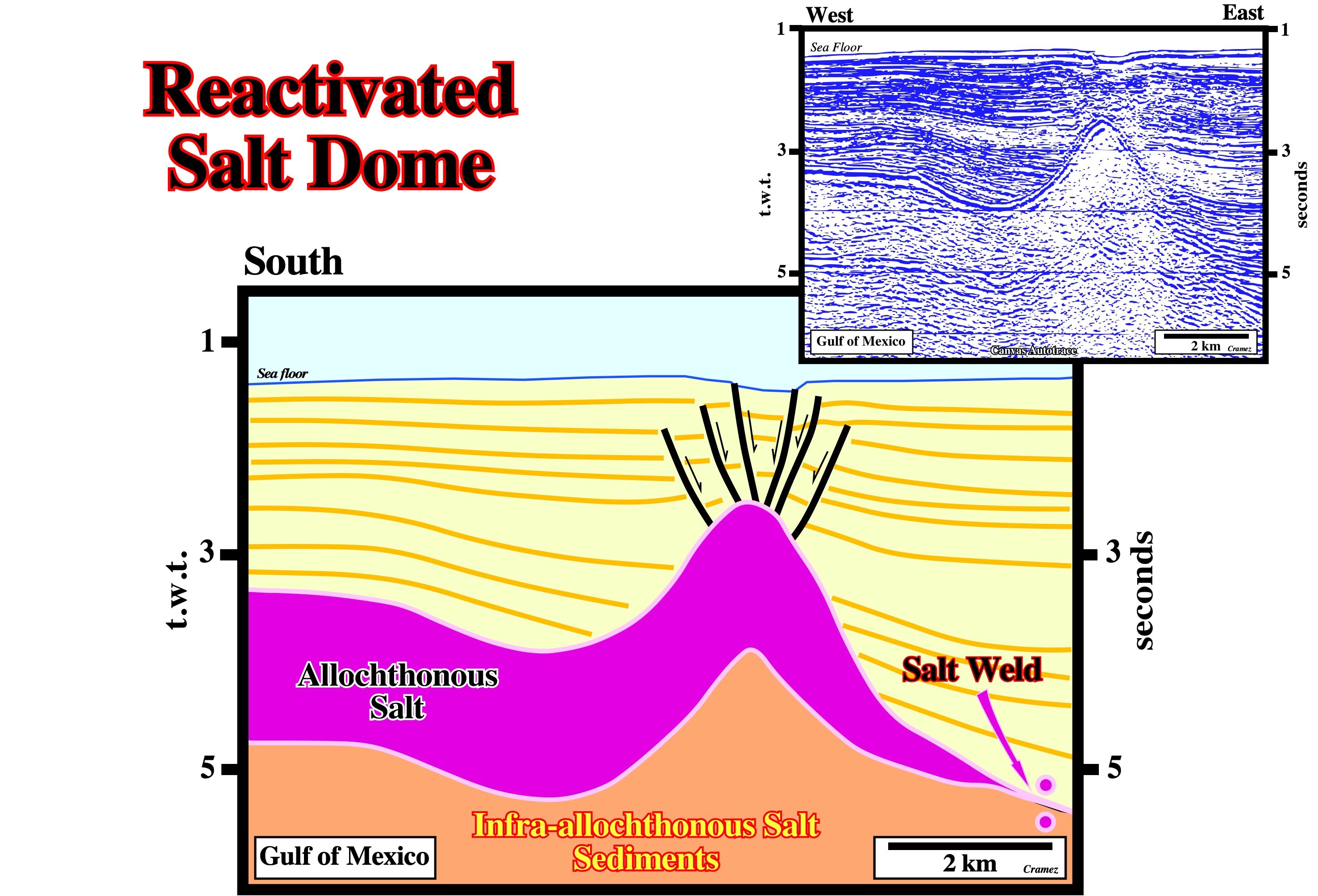
On this tentative interpretation, the stretching faults (probably with radial geometry), on the top of the reactivated diapir, affect the sea floor and so, strongly, suggest the reactivation still is going on. The sediments overlying the salt show a regional northward thickening, which seems to fit with the salt thickness. The upward reactivation of the salt lengthened the sediments obliging them to accommodate the volume conditions (nature abhors a vacuum).
Reactivation
Deformation of a salt sheet to act as a second-generation diapiric source layer by differential loading or burial below the level of neutral buoyancy. Deformation involves local upwelling of salt and sheet segmentation.
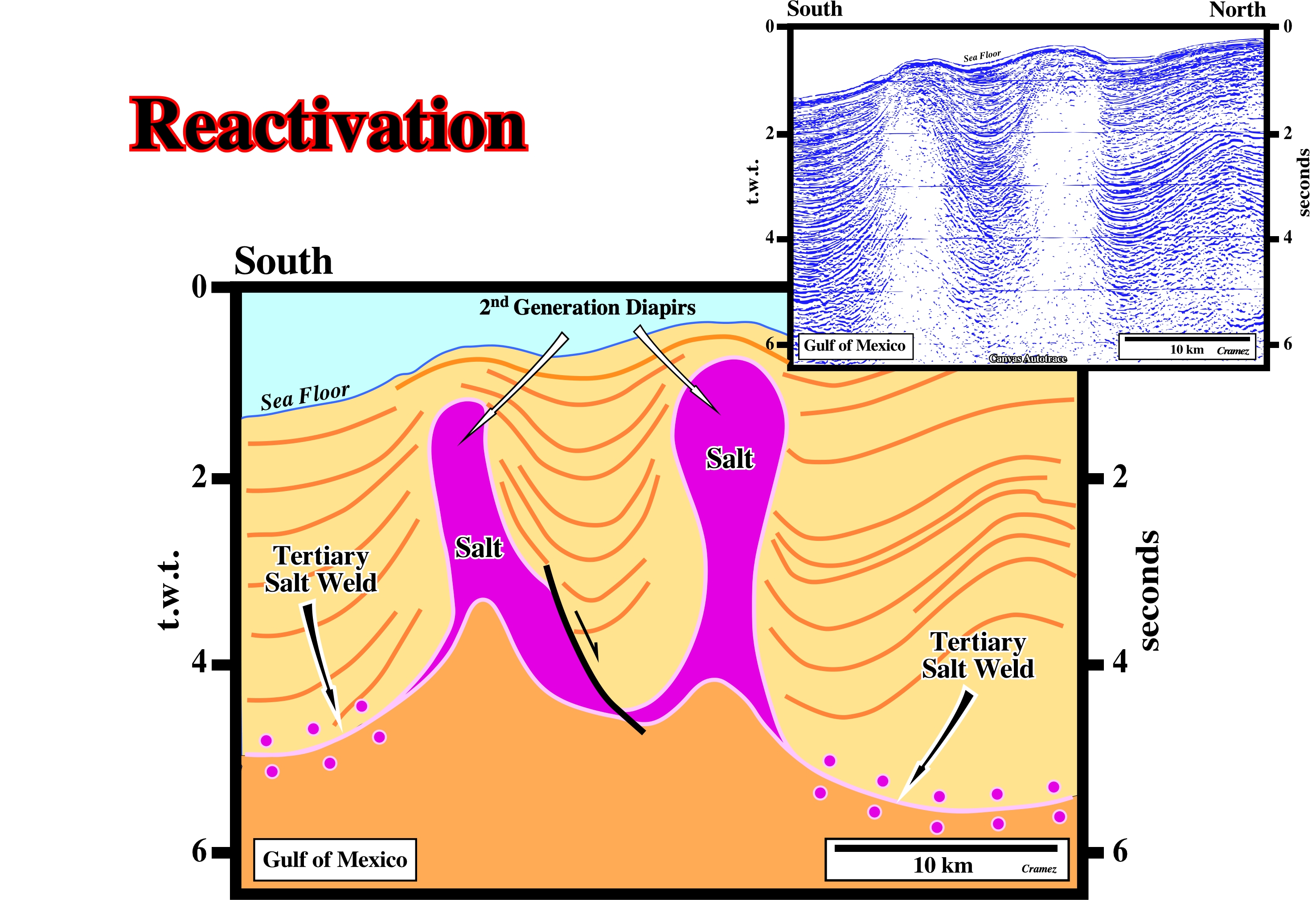
The deformation of the sediments overlying the allochthonous salt created two nice 2nd generation reactivated salt domes as the majority of the salt was evacuated creating a tertiary salt weld.
Reactive Diapir
When the pressure within the salt body becomes sufficiently high it may be able to push through its overburden (forceful diapirism). Many salt diapirs may contain elements of both active and passive salt movement. An active salt structure may pierce its overburden and from then on continue to develop as a purely passive salt diapir. When salt layers do not have the conditions necessary to develop passive salt structures, the salt may still move into, relatively, low pressure areas around developing folds and faults. Such structures are described as reactive.
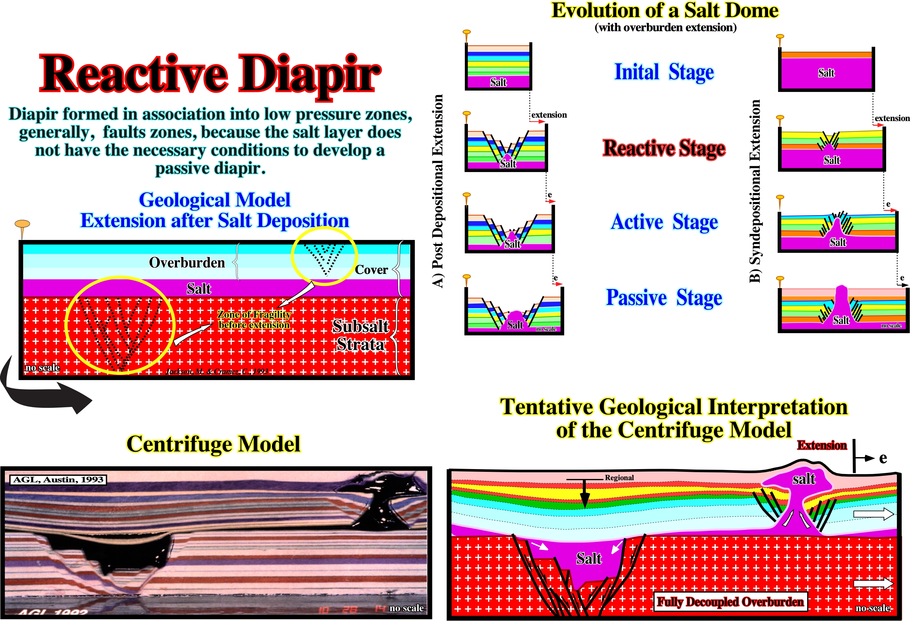
Reactive salt diapir or diapir salt structures are known in almost all sedimentary basin with a significant salt layer. In the Western Africa offshores, they are quit frequent in association with the formation of salt rafts, i.e., in the pre-raft and raft geological domain where extensional (lengthening) tectonic regimes are predominant. In fact, the lengthening of the overburden created by normal faulting that favors the reactive diapirism, even if the salt layer has not the necessary conditions to develop a passive diapir. The same is true in association not only with extensional strike slip faults (margin fractures zones in West Africa offshores), but with compressional strike-slip faulting as well. The pull-apart diapirs described by Ruig (1995) in southern Prebetic mountains can be considered as examples of the the last case. In the geological model for extension after salt deposition, the centrifuge model suggests that the salt can move downward filling the graben structure of the subsalt strata created by lengthening, as well as, it can move upward forming a reactive diapir before it reaches the surface.
Reactive Stage
When there is the conditions to develop passive salt structures, the salt may still move into relatively low pressure areas around developing folds and faults.
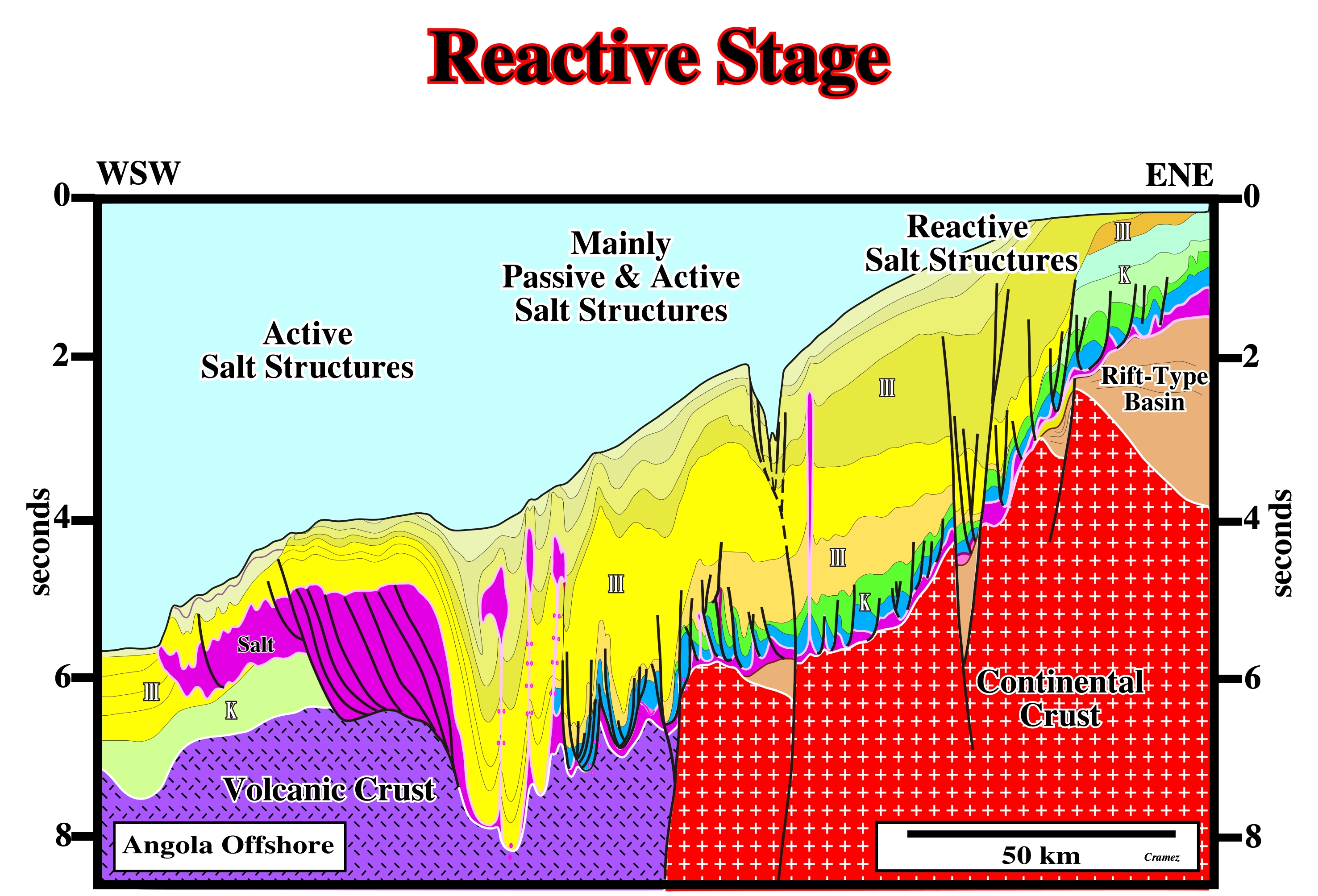
On this tentative interpretation of a Canvas autotrace of a composite seismic line from Angola offshore, from the conventional offshore to deep water, reactive salt stage, in which reactive salt domes are preponderant, seem to passes progressively to a passive stage, in which passive salt structures are predominant, before reaching an active stage, near the western limit of the Angola-Congo-Gabon salt geographic basins, in which the salt layer is thickened by thrusting.
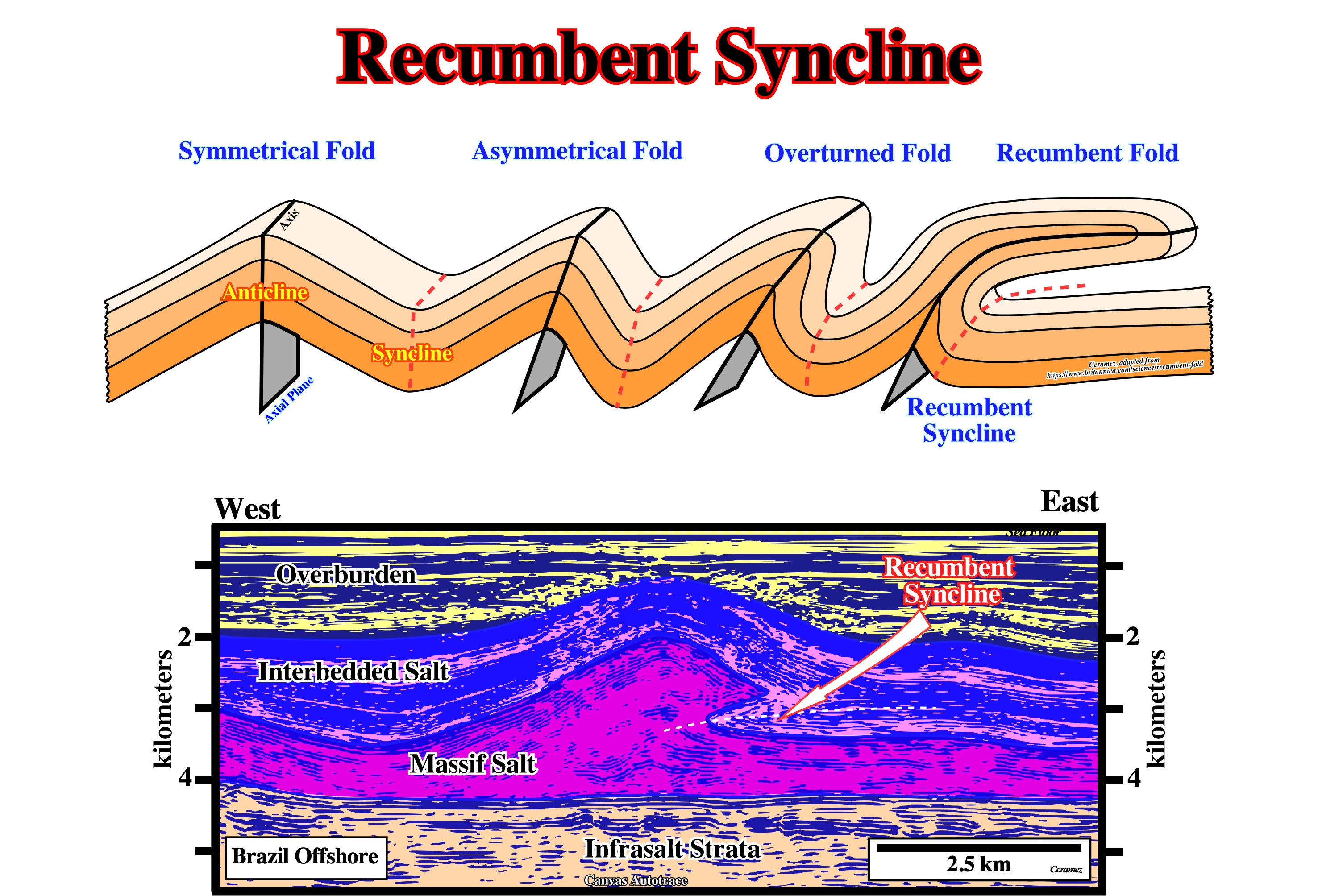
Recumbent Syncline
A recumbent syncline has an essentially horizontal axial plane. When the two limbs of a fold are, essentially, parallel to each other and thus, approximately, parallel to the axial plane, the fold is called isoclinal.
Folds can be symmetrical, when the axial plane is vertical, asymmetrical when the axial plane is inclined, overturned fold, or overfold, when the axial plane inclined to such an extent that the strata on one limb are overturned and recumbent when the axial plane is, more or less, horizontal. In salt basins, as in Angola and Brazil offshore recumbent folds, with the recumbent anticlines and synclines, are developed, often, in association with halokinesis, as illustrated on the above tentative geological interpretation of a Canvas autotrace of a Brazil offshore line. In this this area, above the massif salt, characterized to have few or no reflections, there is a interval formed by interbedded clastic and salt, characterized by a lot of seismic reflections quite deformed by halokinesis.
Regional Elevation (Hossack, J., 1995)
The level to which a key bed will return in the undeformed state. Regional elevation is a key idea used in section balancing.
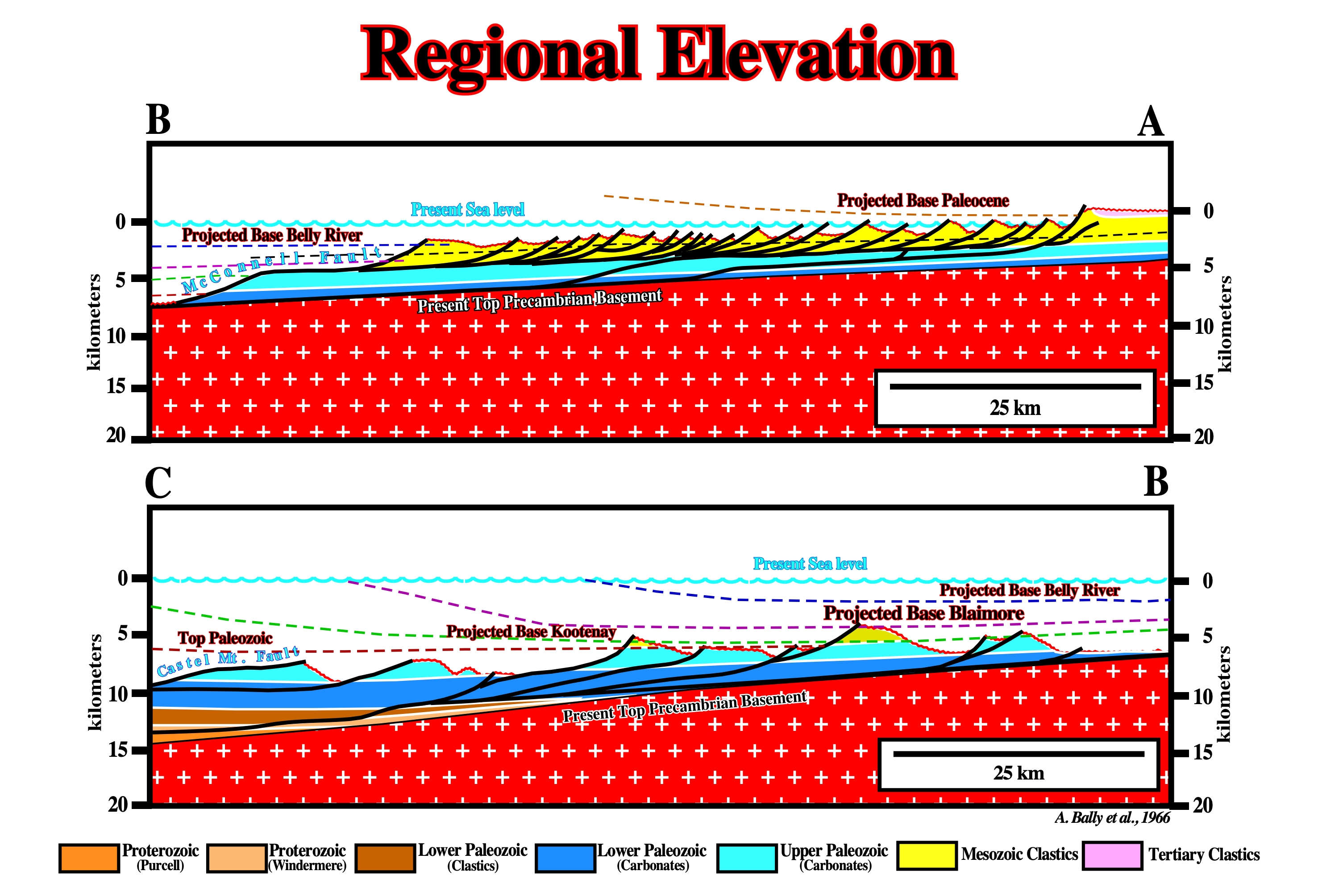
The regional elevations of the stratigraphic different intervals are, easily, recognized on this geological restoration (Rocky Mountains) proposed by Bally in 1966.
Regression
Seaward displacement of the coastal deposits. It happens during a decelerated increasing of the relative sea level fall with a terrigeneous influx strong enough to displace seaward the depositional coastal break. A progradational or forestepping interval emphasizes always a regressive interval.
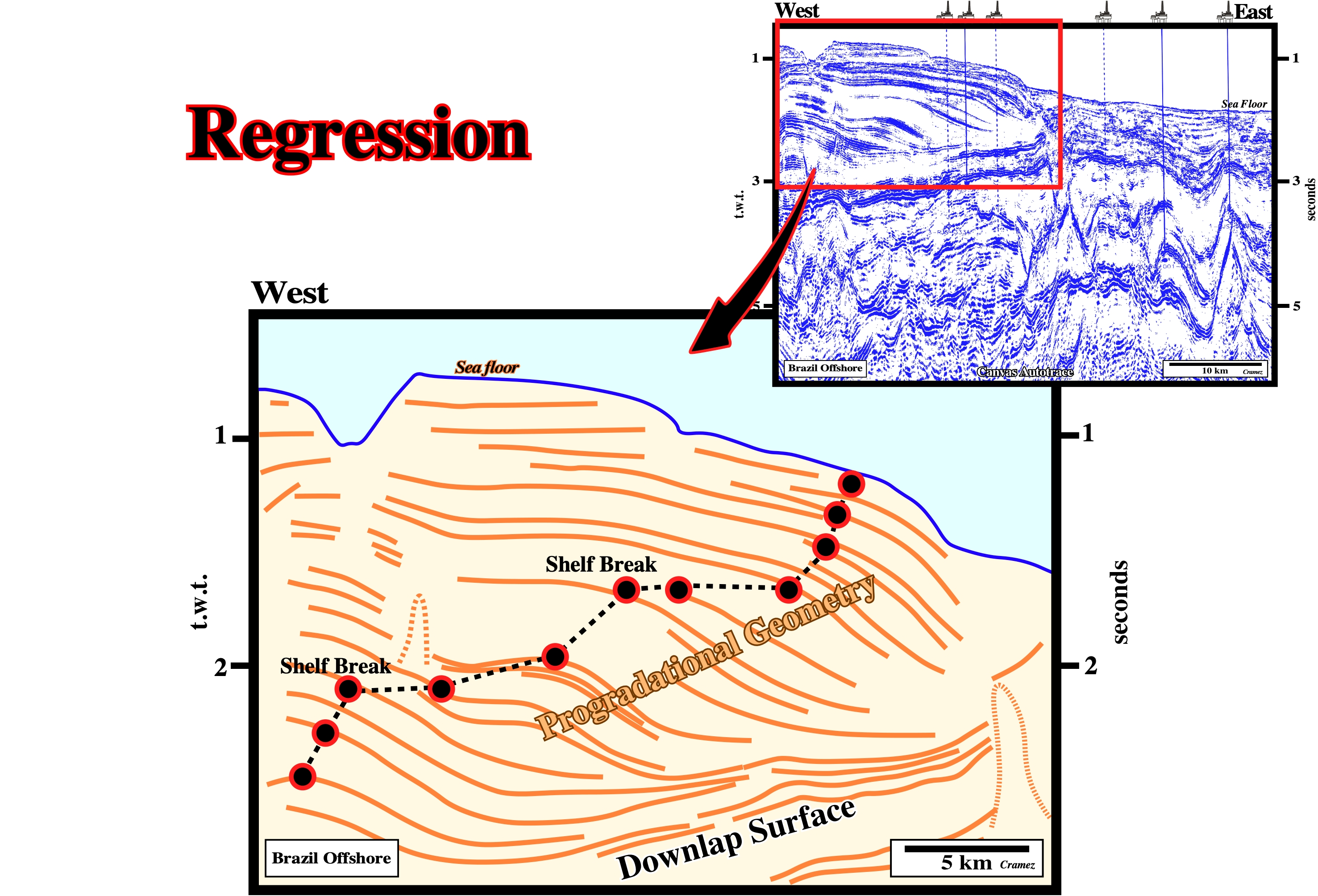
Regressive intervals with their typical forestepping geometry are well recognized in Tertiary deposits of Brazil offshore as illustrated on this preliminary tentative interpretation of a Canvas autotrace. In this particular case, there is outbuilding (progradation) and upbuilding (aggradation), which suggests an area a strong terrigeneous influx. The shelf breaks mark the limit between the successive continental platforms (shelf) and continental slope.
Relative Sea Level Change
A decreasing or increasing in the space available for sediments. It is created by combination of subsidence and eustasy. A relative sea level fall, if big enough, can create an erosional surface, i.e., an unconformity (sequence boundary in sequence stratigraphic parlance) and induce turbidite deposits in the deepest part of the basin. A relative sea level rise, in other others, an increasing in accommodation is always required to deposit transgressive or regression sedimentary intervals.
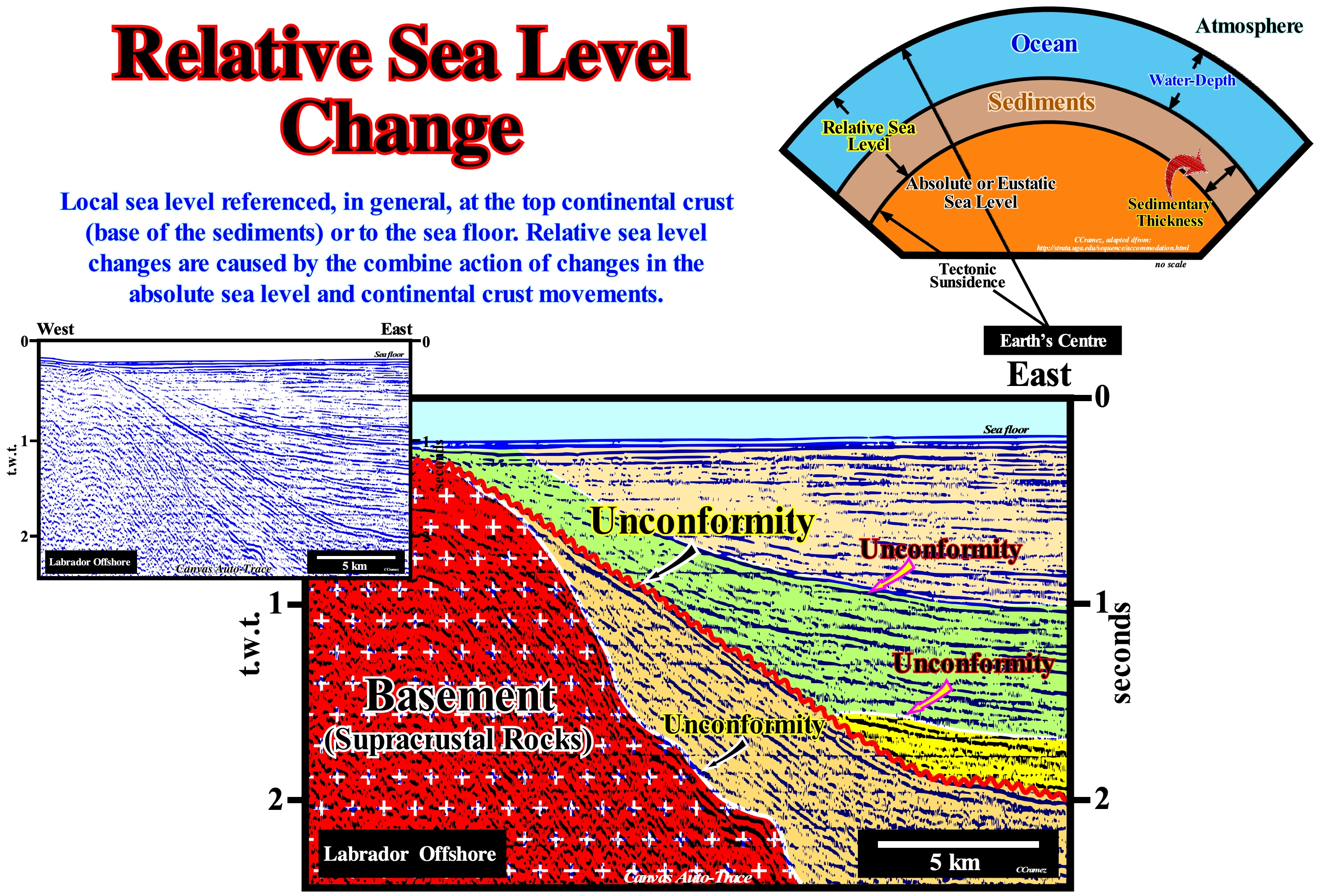
Although global sea level fluctuations result, largely, from the growth or melting (partial or total) of glaciers and ice caps, as well as changes in the volume of ocean basins (configuration of the continental margins and ocean floor), there are also a series of regional geological processes that can change the positions of the relative sea level, which affect the position of the shoreline in a given area. These regional processes include: (i) Thermal expansion of ocean water (steric sea level rise) ; (ii) Variations in the melt water load ; (iii) Isostatic readjustment ; (iv) Uplift or subsidence of coastal areas induced by different tectonic and anthropogenic processes ; (v) Compensatory subsidence (i.e., lateral flow of mobile stratigraphic intervals) ; (vi) Sedimentary load ; (vii) Compaction, etc. Relative changes in sea level may, also, result from geodetic variations such as fluctuations in the Earth's angular velocity or polar traction (geological phenomenon caused by changes in the flow of the liquid part of the Earth's core which changes the magnetic field and thus the position of the North magnetic pole). It is interesting to note that tidal records suggest a global average rise in sea level over the last century. Although there is no compelling evidence on the rising values. Some alarmists, such as the US Environmental Agency, predict a global sea level rise of about 15 m (20 feet) by 2050 (± 3 mm per year) induced by anthropogenic global warming (if it exists). Global and relative sea level changes have, practically, existed since the Earth's formation. Without an increasing in shelfal accommodation (space available for sediments), sedimentation on Earth would be impossible. In sequential stratigraphy it is fundamental not to confuse the relative sea level with absolute or eustatic sea level. The relative sea level is local and referenced to any fixed point on the Earth's surface, which can be the base of the sediments (top of the continental crust) or the sea floor. The absolute (eustatic) sea level is supposed to be global and referenced to the Earth's center. The relative sea level is the result of the combined action of absolute (eustatic) sea level and tectonics (subsidence or uplift of the sea floor). The absolute sea level is the result of the combined action of: i) Tectono-Eustasy that is controlled by the volume variation of the ocean basins in association with oceanic expansion following the breakup of the supercontinents ; (ii) Glacio-Eustasy, which is controlled by the variation of water volume of the oceans as a function of the amount of ice (assuming that the amount of water in all its forms is constant since the formation of the Earth, around 4.5 Ga) ; (iii) Geoidal-Eustasy, which is controlled by the distribution of ocean water caused by variations in the Earth's gravity field (where gravity is stronger than normal, sea level is thrown to the center of the Earth) and (iv) Steric sea level rise or thermal expansion of the oceans (if the temperature increases, the density of the water decreases, and for a constant mass, the volume increases). During a given geological time, the combination of the eustatic curve (curve the absolute sea level changes) and tectonic (subsidence of the sea floor, when the predominant tectonic regime is in extensional or uplift, when the predominant tectonic regime is compressional) gives the curve of the rate relative sea level change. On this tentative geological interpretation of a Canvas auto trace of a Labrador offshore seismic line, the reflector terminations (lapouts) that define the seismic surfaces, such as the unconformities, allow the reconstitution of relative sea level variations that induced the deposition of the sedimentary column. The unconformity between the basement (supracrustal rocks) and the base of the sediments (divergent margin) was, tectonically, enhanced (angular unconformity). The same goes for the unconformity emphasized by the red wavy line, albeit differently. The relative sea level fall that induced then unconformity was later deformed by an isostatic differential uplift of the continent which created a significant the relative sea level fall that created the erosional surface, responsible, the underlined unconformity in red. The marine onlaps (especially the yellow range) and the upper coastal onlaps emphasize relative sea level rises (marine ingressions).
Relic Roller
A continuous salt evacuation from the upthrown fault block (footwall) can, completely or almost completely, destroy a salt roller. Some call relic roller the last stage of salt evacuation from a salt roller.
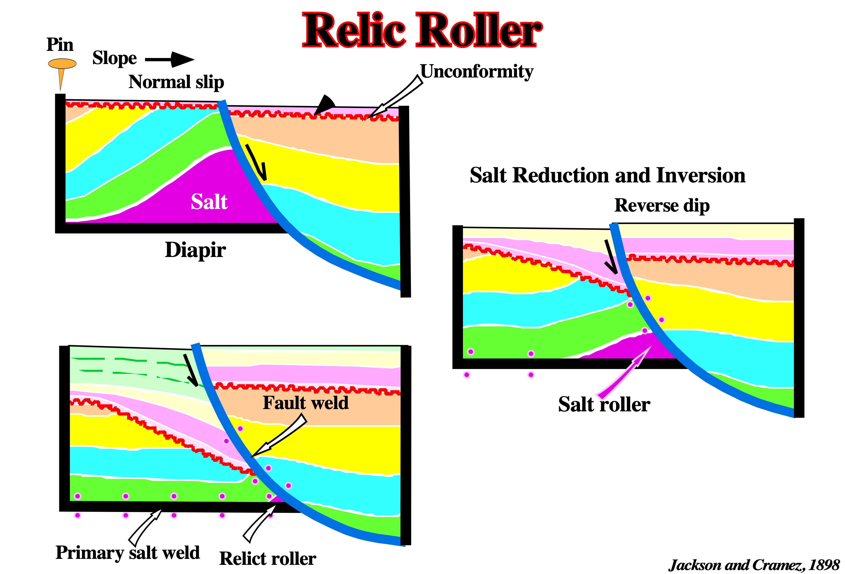
The salt evacuation progressively creates (i) a faulted diapir, (ii) a salt roller, (iii) a relic roller and finally just a primary salt weld and an apparent reverse-fault. The evacuation of the salt from the footwall, as illustrated above, changes, by inversion, a normal listric fault in a normal fault with a reverse geometry, which some call apparent reverse-fault.
Residual High
An intermodal antiform with a core of salt that may be disconnected or not from the adjacent domes.
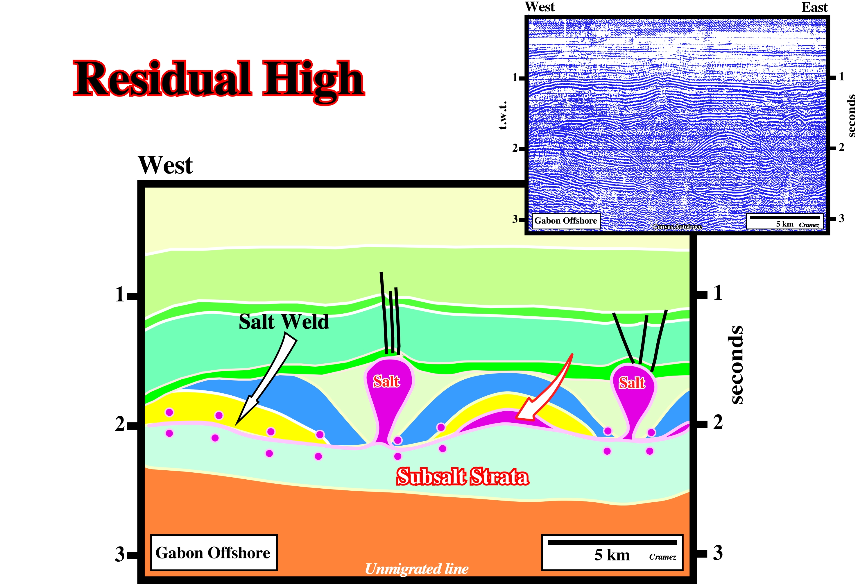
Turtle back structures can have a residual salt high or not as illustrated above. On the left, a primary salt weld took place after a completely salt evacuation. On the contrary, on the right, the salt evacuation was not total, so a residual high still remains in the core of the structure.
Restoration
See: Palinspastic Section.
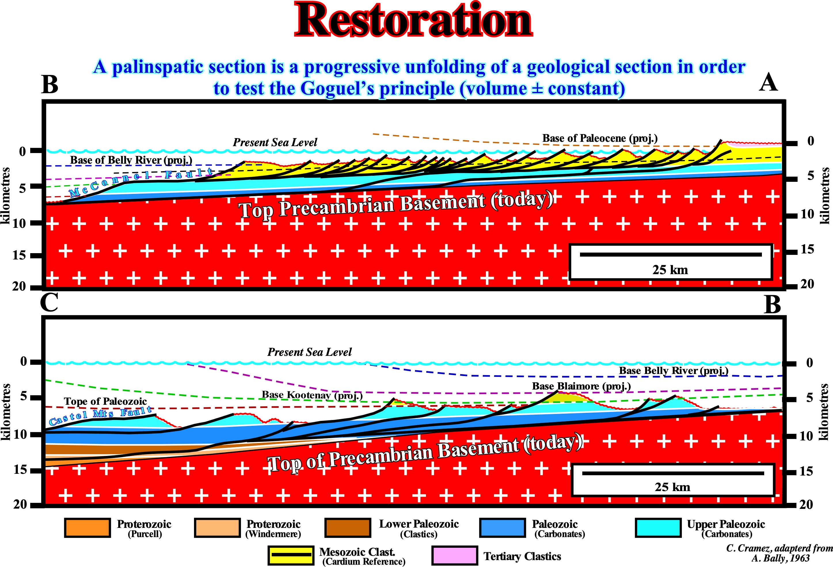
There are, at least, four the main kinematic models for restoring geological sections (either made with field data or made from tentative geological interpretations of seismic lines (in depth): (i) Fault-bend-fold method ; (ii) Rigid block rotation ; (iii) Vertical and inclined shears and (iv) Flow parallel to the faults (http://ftp.ufrn.br/pub /biblioteca/ext/bdtd/AlexFA_Cap9_ate_final.pdf). The first method assumes that the deformation of the layers is accompanied by flexural sliding along the bedding planes that function as slip surfaces where deformation between the strata is minimal. The rigid block rotation restoration (does not apply to areas with folded structures) preserves the lengths and internal angles, being applicable to faulted sections with non-deformed blocks, as found in domino-like structural styles. In curvilinear faults, the collapse of the hangingwall can be devised by linear homogeneous displacements along the vertical or inclined sliding planes at an angle to which a series of points located in the hangingwall are translated parallel to the regional diving line. The flow parallel to the fault method consists of moving material points in the faulted block along lines parallel to the main fault. In the section shown in this figure, all imbrications and thrusts (reverse faults dipping more than 45°) are shown in their present-time and restored positions. The displacements along the section line were neglected and, to facilitate construction, the restoration was made in relation to the present-time dip of the basement and an unspecified reference point was taken to the West. Nowhere in the section or its restoration, the Paleozoic is, completely, absent. The geoscientist who made this palinspathic section assumed that no major structural unit was eliminated by erosion. He calculated a sedimentary shortening in the order of 50%, that is, a shortening of about 160 km to the "Main Mountains" (Main Range of Canadian geoscientists). The understanding of fold/fault relationships is of little importance to predict orogenic contraction when geological or seismic data are available to indicate the stratigraphic cut-off of the faulted blocks (reverse faults, thrusts). On the contrary, a perfect understanding of the fold/fault relationships is fundamental, when the location of a cut-off stratigraphic omission is in the lower block-failure (cut-off lines are where a layer gets truncated by a fault, and for a given offset layer there are two such cut-off lines on either side of the fault ; when an exploration well cross a normal fault there is a stratigraphic interval that is not recognized by the well that geoscientists call cut-off stratigraphic omission). An anticline structure (a convex fold in the direction of the most recent strata, created by a compressional tectonic regime, i.e., shortening) can be interpreted as: (i) A fold induced by a fold propagation fault, i.e., when the fold forms at the end of the fault, where movement along the detachment plane has stopped, but not in the upper block (footwall) of the fault ; (ii) A transported fault propagation fold, when the fold in the upper failed block forms at the forefront of reverse fault ; (iii) A simple ramp hanging-wall anticline. The main errors result from the confusion between the case of a fold induced by the propagation of a fault (i) and the others (ii) and (iii). In the case of a transported fault propagation fold (ii), the depth displacement is small, while in other cases the displacement is unknown. The line/length balancing and the assumption of a plane deformation are the basic assumptions of Goguel's two-dimensional simple balancing (1948) : (i) A deformation plane within a thrust, with the y-axis perpendicular to the plane of the section ; (ii) A displacement along the faults parallel to the plane of the section. The error induced by the deformation plane in the thrust is related to: (1) A change in volume ; (2) A deformation perpendicular to the plane of the section and (3) A deformation perpendicular to the strata.
Retrogradation
See: Backstepping.
Continentward displacement of the depositional coastal break (roughly, the shoreline) of the depositional surface within the transgressive interval (TI), during the accelerated relative sea level rises (marine ingressions). A retrogradation is, usually, associated with a succession of increasingly smaller progradational sedimentary episodes. It occurs every time a progradational unit does not develop beyond the preceding progradational unit. A retrogradation indicates a series of increasingly important marine ingressions (relative sea level rises) and increasingly smaller sedimentary regressions, with no relative sea level falls between them (eustatic paracycles).
Within a sequence-cycle, the relative sea level rise (sea level, local, referenced to any fixed point of the Earth's surface, whether it be the base of the sediment or the seafloor and that is the result of the combined action of absolute or eustatic sea level that initiates the group of highstand systems tracts (GHST), induces a continentward shift of the depositional coastal break (more or less, the shoreline, especially on the seismic lines, i.e., taking into account that the seismic resolution is in 2D seismic lines around 30/40 meters) on the slope of the depositional surface. Such a displacement of the shoreline creates or increases the continental shelf and the water-depth, as the rise in relative sea level is in acceleration (increasingly important marine ingressions). The rise in relative sea level is not in continuity. Many geoscientists speak of composite marine ingression and single marine ingressions. Single marine ingressions are steps of a composite marine ingression, since a relative sea level rise is, in the majority of the cases, done in steps, as, for instance: (i) Rise in relative sea level of 3 m (single marine ingression) ; (ii) Stability period in relative sea level ; (iii) Relative sea level rise of 5 m (single marine ingression) ; (iv) Stability period in relative sea level ; (v) Relative sea level rise of 7 m (simple marine ingression) ; (vi) Stability period in relative sea level ; (vii) Fall in relative sea level of 10 m (marine regression). In this case, globally, the relative sea level rose 15 meters (composite marine ingression) in acceleration, since single marine ingressions are increasingly greater. The terms single and composite marine ingression should be used whenever clarification is required. The first relative sea level rise, i.e., the first single marine ingression (first eustatic paracycle), is followed by a stability period of the relative sea level, during which the shoreline and the associated coastal deposits move to the seaward, as the sediments prograde towards the continental edge, which is now also the edge of the basin. However the shoreline does not reach the position it had before (retrogradation). Thus the first paracycle-sequence is deposited. The second relative rise in sea level (second single sea ingression), i.e., the second eustatic cycle, which is more important than the first, as the relative sea level rises in acceleration, again, shifts the shoreline landward increasing the extension of the platform and the water-depth. A new period of relative sea-level stability allows, again, the displacement of the shoreline seaward and the deposition of progradational sediments (second sequence-paracycle), but without the shoreline reach the position it had in the end of the preceding sequence-paracycle, which, globally, corresponds to a retrogradation as illustrated in this tentative geological interpretation of a Canvas autotrace of a detail of seismic line from Indonesia offshore. This mechanism (relative sea level rise - stability of the relative sea level - relative sea level rise) continues until the first rise, in deceleration, in the relative sea level (smaller than the previous one), which initiates the deposit of the highstand prograding wedge (LPW). What certain geoscientists, incorrectly (in our opinion), call transgression or the displacement to the continent of the shoreline and associated coastal deposits, is nothing more than a succession of ever larger single marine entrances and increasingly, more and more, sedimentary regressions small. It is this set of marine ingressions and sedimentary regressions, which globally has a retrogradational geometry, which Cesare Emiliani (1992) called "Transgressions" (not transgression). The internal configuration of sequence-paracycles is progradation. Between consecutive eustatic paracycles there is no relative sea level fall. Sediments are deposited during the stability period of relative sea level that occurs between two eustatic paracycles. In other words, between two eustatic paracycles there is any erosional surface (unconformity), but, just, a ravinement surface. On this tentative geological interpretation of an auto-trace of a detail of a seismic line from Borneo offshore, within the considered sequence-cycle, limited by two unconformities (in blue), it is easy to recognize the sequence-paracycles, which here correspond to sedimentary systems tracts, which form the lower subgroup of highstand systems tracts called Transgressive Interval (TI). It is possible that in this particular case, each sequence-paracycle corresponds to a unique sedimentary systems tract. The retrogradation of the depositional coastal break of the depositional surface (chronostratigraphic line), which corresponds, more or less, to the retrogradation of the coastline, is obvious.
Reverse-Fault
A fault on which the hangingwall appears to have moved upward relatively to the footwall. The dip of the fault is usually greater than 45°.
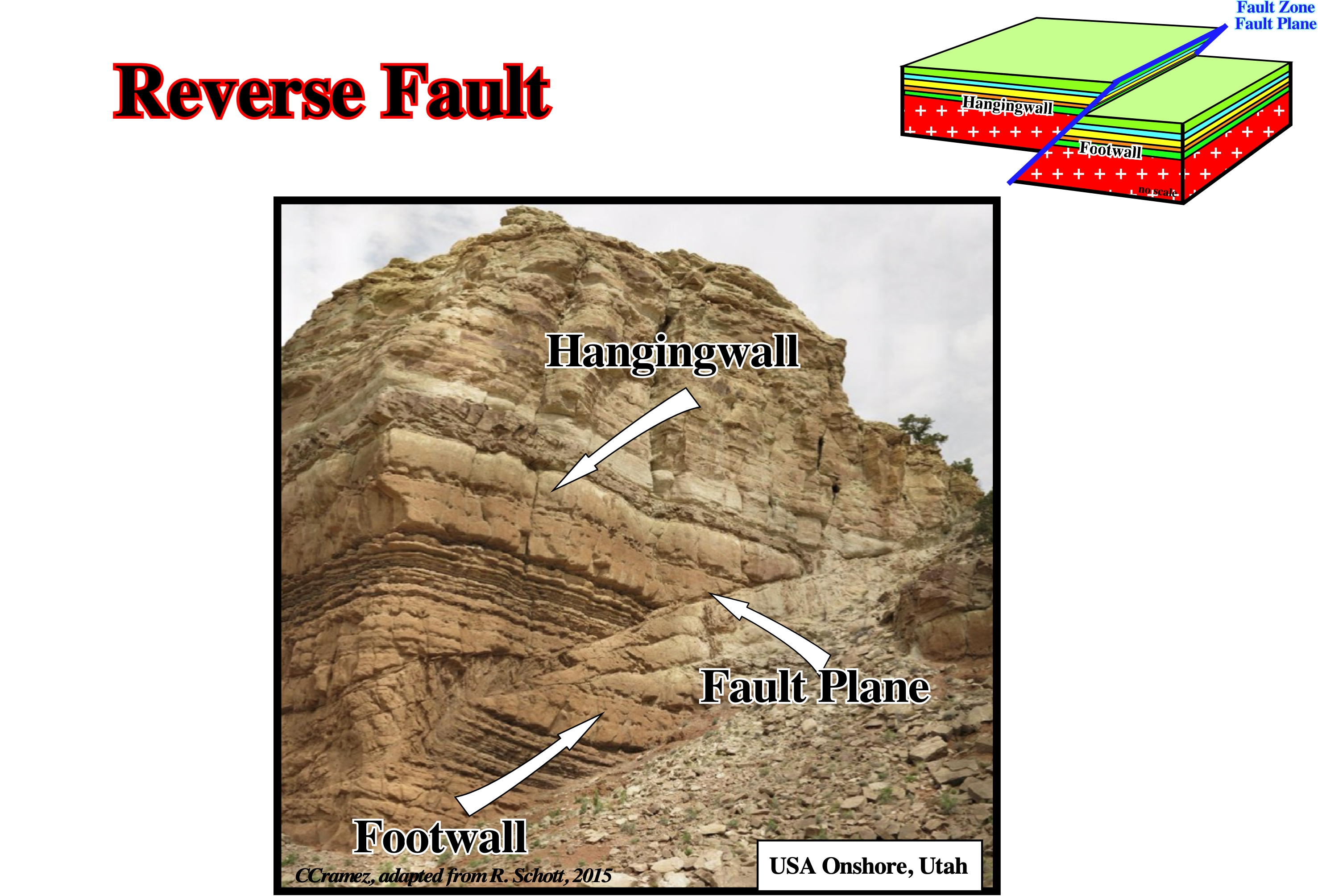
Reverse faults shortened the sediments. They are induced by compressional tectonic regimes, in which the σ3 is vertical. They are often associated with cylindrical-folds. The shortening takes place mainly in the hangingwall where folding takes place contributing so to shortening. A compressional tectonic regime is characterized by an ellipsoid of the effective stresses (σg, geostatic pressure ; σp, hydrostatic pressure and σt, tectonic vector) with a σ1 horizontal (major axis of the ellipsoid). When σ2 (middle axis of the ellipsoid) is horizontal and σ3 (small axis of the ellipsoid) vertical, the sediments are shortened by cylindrical folds, reverse faults and thrusts. When σ2 is vertical and σ3 (small axis of the ellipsoid) horizontal, the sediments are shortened by strike slip faults and conical folds.
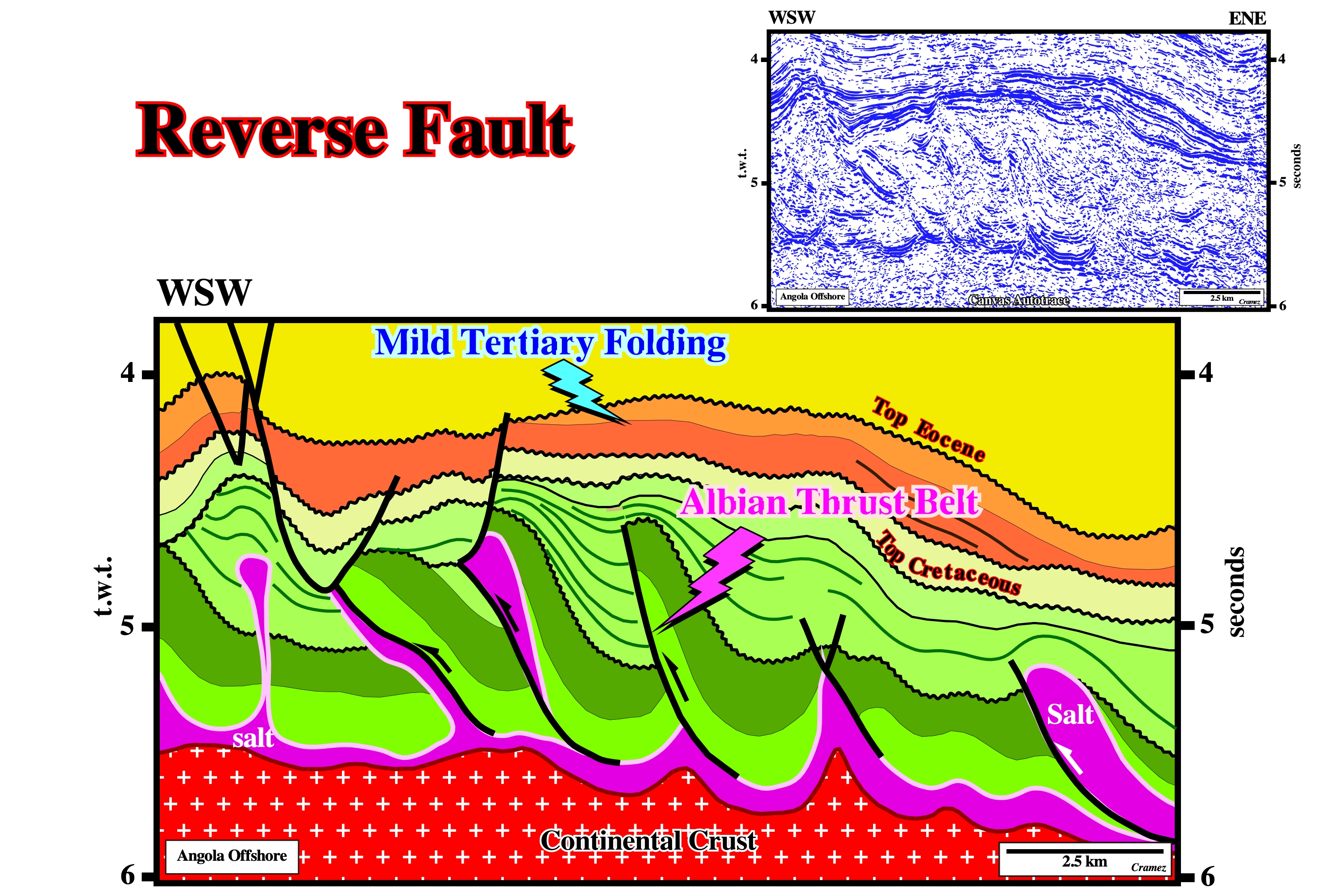
In Angola offshore, as this tentative geological interpretation suggested (uninterpreted Canvas autotrace in the right corner of the figure) reverse faults (Albian thrust belt) are present in certain parts of the offshore in association with more or less local compressional tectonic regimes. It is interesting to notice on this example, that in addition to the Albian shortening, there is also a Tertiary shorting represented here by a large mild folding. The pull-ups (seismic pitfall) at the base of the autochthonous salt layer are induced not only by the reverse faulting, but the lateral changes in salt thickness as well.
Rheology of Overburden
Behaviour of the overburden under stress (Rheology is the science of deformation and flow within a material). The overburden is, commonly modelled as one of two ideal types of behaviour: (i) Fluid and (ii) Brittle. Both approximations treat sediments as a continuum, i.e., a set of homogeneous elements (all fluid or britlle characteristics vary continuosly throughout the fluid). Fluid behaviour (recoil) is modelled as a power-law, time-dependent flow in which shear viscosity decreases as rate of shear increases. Brittle behaviour of the shallow crust (less than, 8 km deep) has been simulated by experimental rock mechanics.
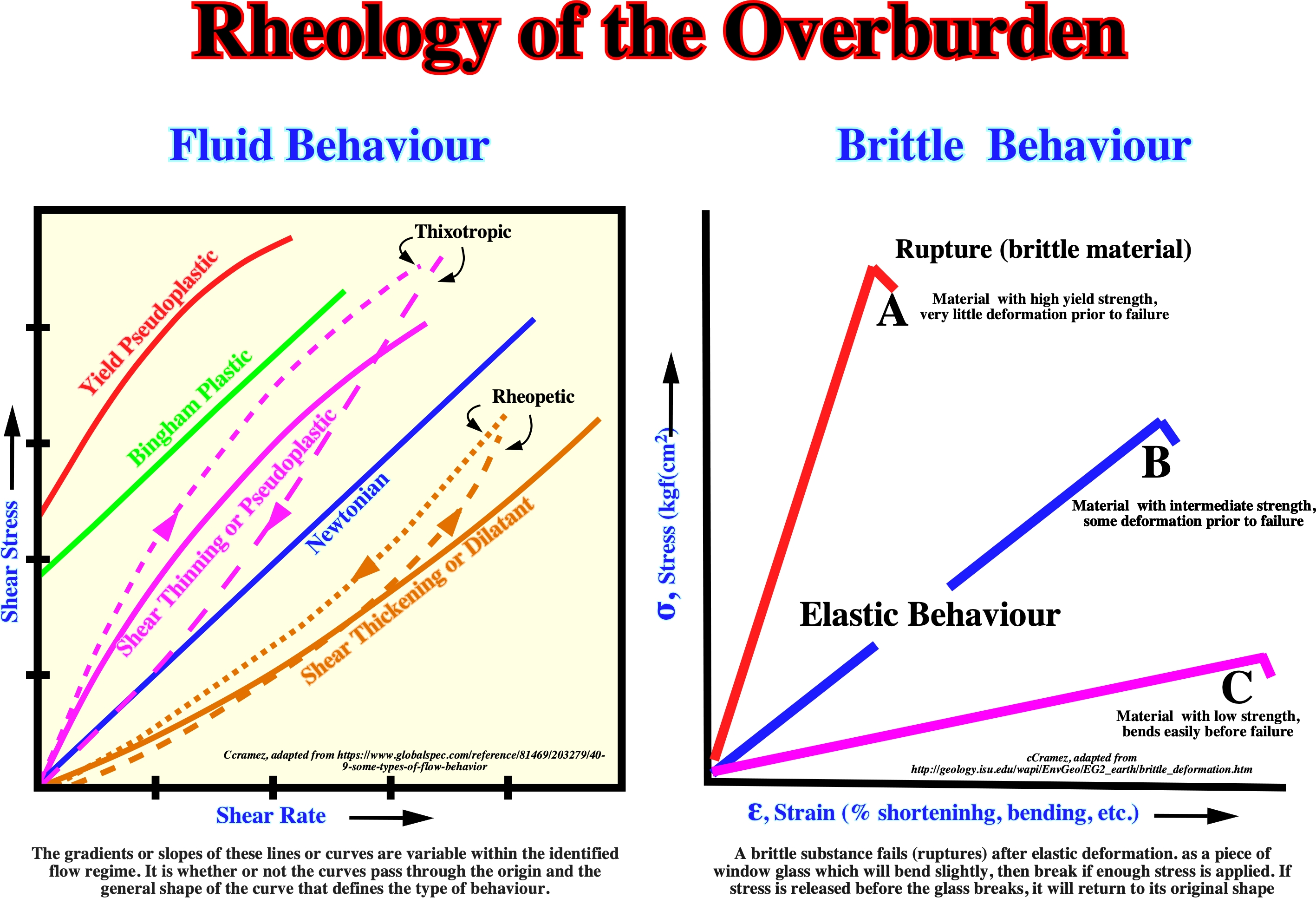
Rheology is the science of deformation and flow within a material, i.e., the branch of physics which deals with the deformation and flow of materials, both solids and liquids. A brittle or rigid material is a material that fractures at less than 3-5% deformation or strain. When tested to failure under conditions of triaxial compression, many competent rocks exhibit a relationship between principal stresses at failure, which is represented by the empirically derived linear equation: σ1 =σ0 + kσ3. Where σ0 is the uniaxial compressive strength and k is a constant. Other rock types exhibit a non-linear relationship between principal stresses at failure. In these types of tests the specimens fail in shear. Usually, the specimens fail along only one shear plane. Occasionally specimens exhibit two conjugated shear planes, with opposite shear sense. The angle between them, which is, often, considerably less than 90°, is bisected by the axis of maximum principal stress. Fluid material is a material that when deformed does not have an instantaneous and totally recuperation of its initial state, without loss of coherence. A perfect fluid offers no resistance to change of shape (i.e. has zero viscosity). The rheological models are largely insufficient to take into account all cases occur in Earth’s surface. The rheological laws must take into account the different possible scales, as for instance: time (1s, 1h, 1 year, 106 years, etc.), length (100 A°, 1 mm, 1 m, 1 km, 100 km, etc.), temperature, pressure, etc.. Crustal materials have mechanical behaviors between two extreme cases: (i) Fluid, when they have small and finite deformation under hydrostatic pressure. ; (ii) Solid, when they have finite deformation under tangential or hydrostatic stresses. On the other hand, rheological laws are dependent of: a) Effective stresses ; b) Stresses time-duration ; c)Temperature and Pressure. A atmospheric pressure (roughly 1 kg cm-2) and at 25°C, a rock can have an elastic behavior. However, at 500 At of pressure and 250°C, it behaviors as plastic. In order to determine the mechanical behavior of a rock, one needs to know: A) The Stress Field (tensor) ; B) The Strain Field (tensor) and C) The Stress - Strain ratio . The mechanical behavior can be approach whether by mechanical analog or under experimental conditions. (Rheology is the science of deformation and flow within a material. It is a branch of physics which deals with the deformation and flow of materials, both solids and liquids.
Ridge (Mid-oceanic)
Elongated, steep-sided elevation of the ocean floor, along which new oceanic crust takes place.
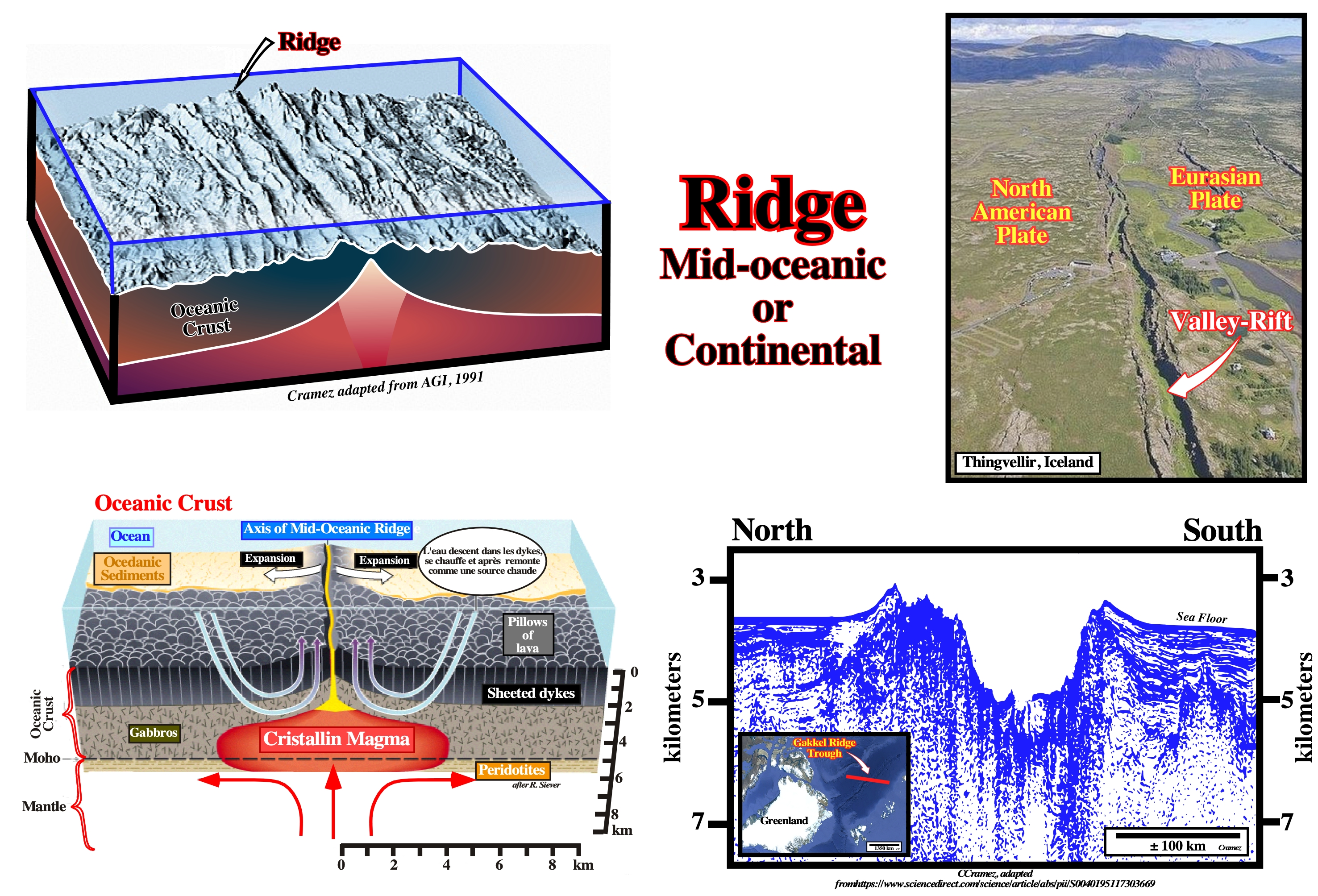
Contrariwise to the subaerial volcanic crust, the ridges forming the oceanic crust have a linear geometry, in surface, and a vertical geometry in section. Actually, they are are the result of the agglutination the sheet dikes. Subsequently, the associated magnetic anomalies are quite obvious.
Ridge Push Forces
Local compressional tectonic regime created or associated by sea floor spreading.
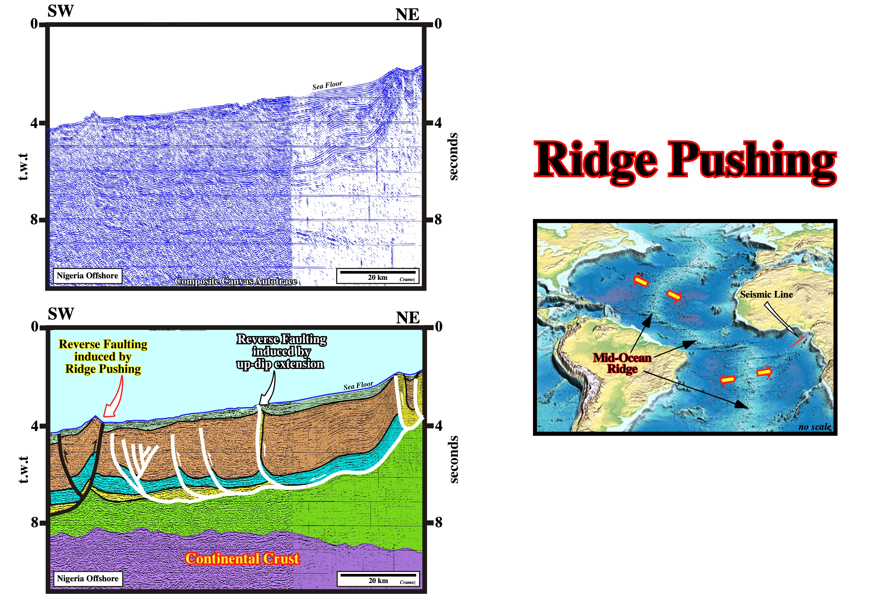
Fold-belts located in ultra deepwater, and particularly those having a landward vergence, have been explained by ridge push forces. This is clear in Nigeria offshore as well as in Gulf of Mexico, in which the Perdido Fold Belts is paramount.
Rim Syncline
Synkinematic synform depocenter located around salt domes.
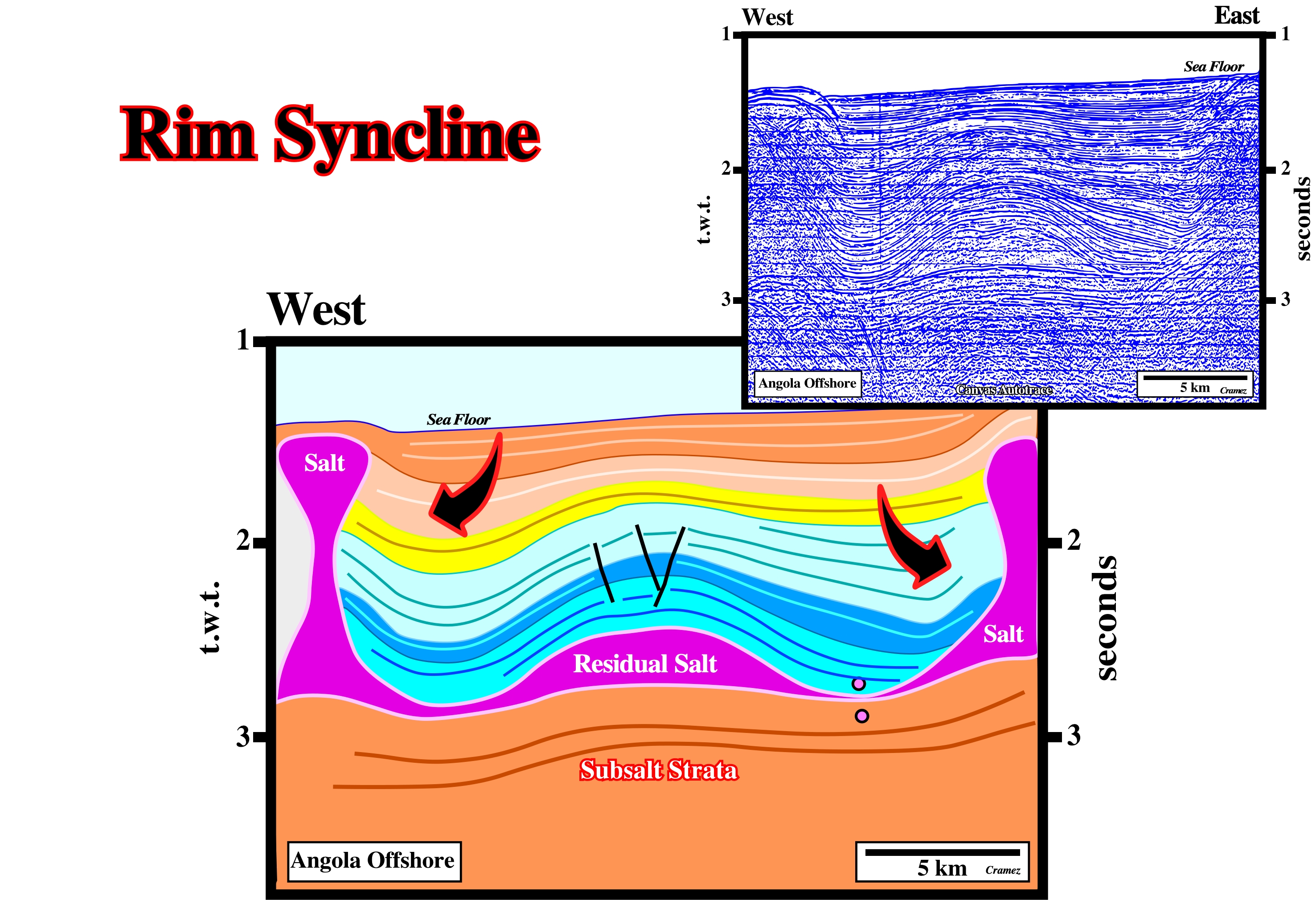
Rim synclines located around salt domes created very often turtle back structure (inversion) or apparent turtle back (without inversion) as illustrated. The occurrence of normal faults, contemporaneous of the deformation, in the top of the structures strongly suggest that the overburden was lengthened and not shortened by the salt movements. In geology, the sediments cannot be shortened and lengthened, in the same place at the same time. The structures recognized on this tentative interpretation are antiforms and synforms and not anticlines and synclines.
Rock Salt
See: Salt source layer.
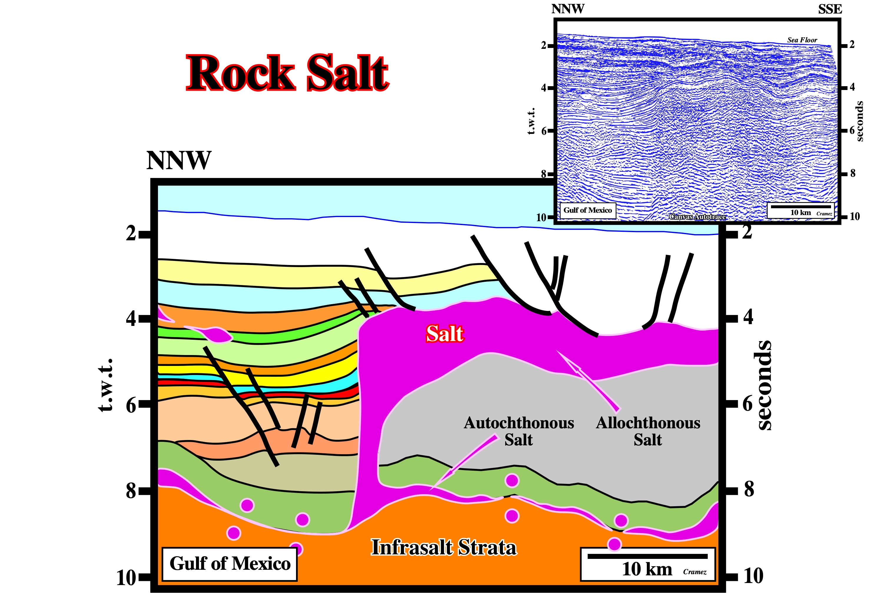
Obvious, the mother salt layer of the allochthonous salt layer is the autochthonous salt layer, in spite of the fact that on this preliminary tentative interpretation of a Canvas autotrace of a Gulf of Mexico seismic line, it is represented, mainly, by salt welds. Under the allochthonous salt, the tentative interpretation is speculative, i.e., according my expectations.
Roho (Diegel, F. A. et al, 1995)
Often, but not always, synonym of Tertiary Salt Weld. Diegel et al. (1995), in Plio-Pleistocene detachment province of Gulf Coast, restricted the term roho to the characteristic discontinuous, high-amplitude seismic reflections caused by remnant salt along salt welds. Roho are also called salt evacuation surfaces or salt withdrawal surfaces.
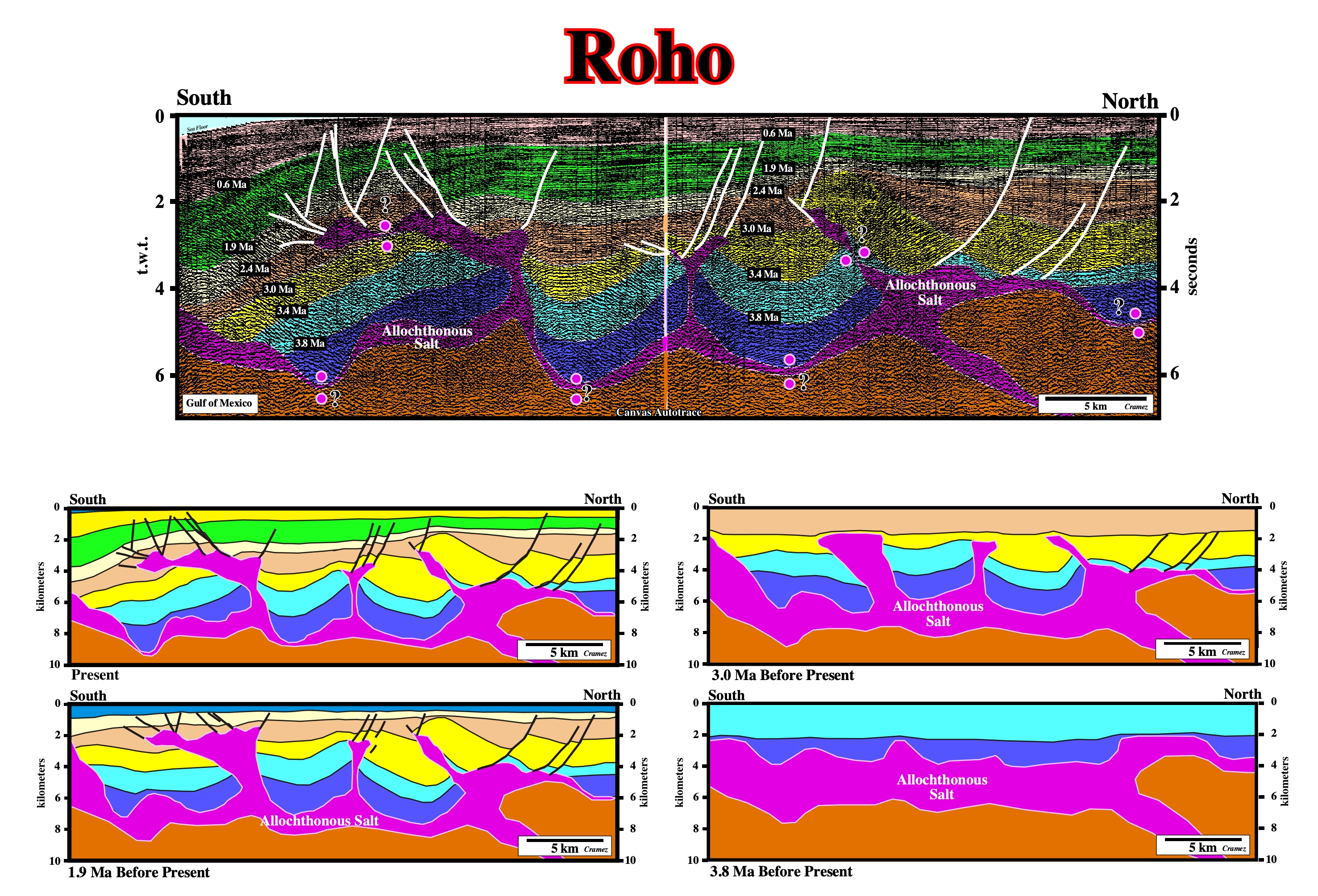
Several potential rohos, i.e., tertiary salt welds can be assumed on the above tentative interpretation of a Canvas autotrace of a GOM seismic line, which were not taken into account on the time restoration of the salt movement since the emplacement of the allochthonous salt nappe (Plio-Pleistocene).
Roho Faults
See: Roho System.
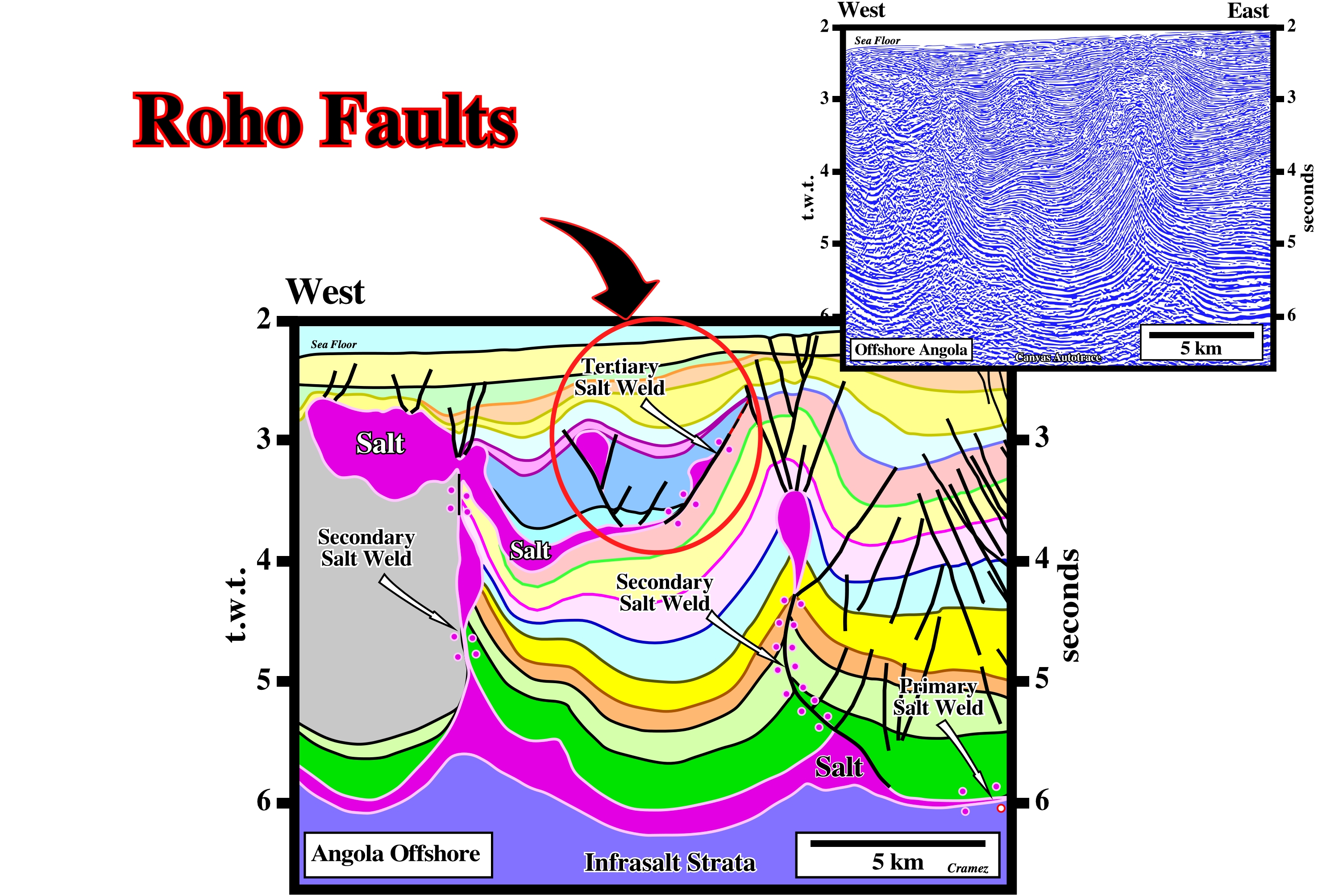
On this tentative interpretation tertiary salt welds are quite evident. Some geoscientists working in this area (Angola offshore) consider the associated faults looking seaward as roho faults following the terminology of some American geoscientists, although the mechanism doesn't seem to be the same, as illustrated below (Roho System).
Roho System
Salt induced growth faults looking seaward (Gulf of Mexico). During a progradational loading, allochthonous salt can evacuated in different ways and given two quite different end-members. One with growth faults looking seaward, roho system, and another, with growth-faults looking landward, known as counter-regional system.
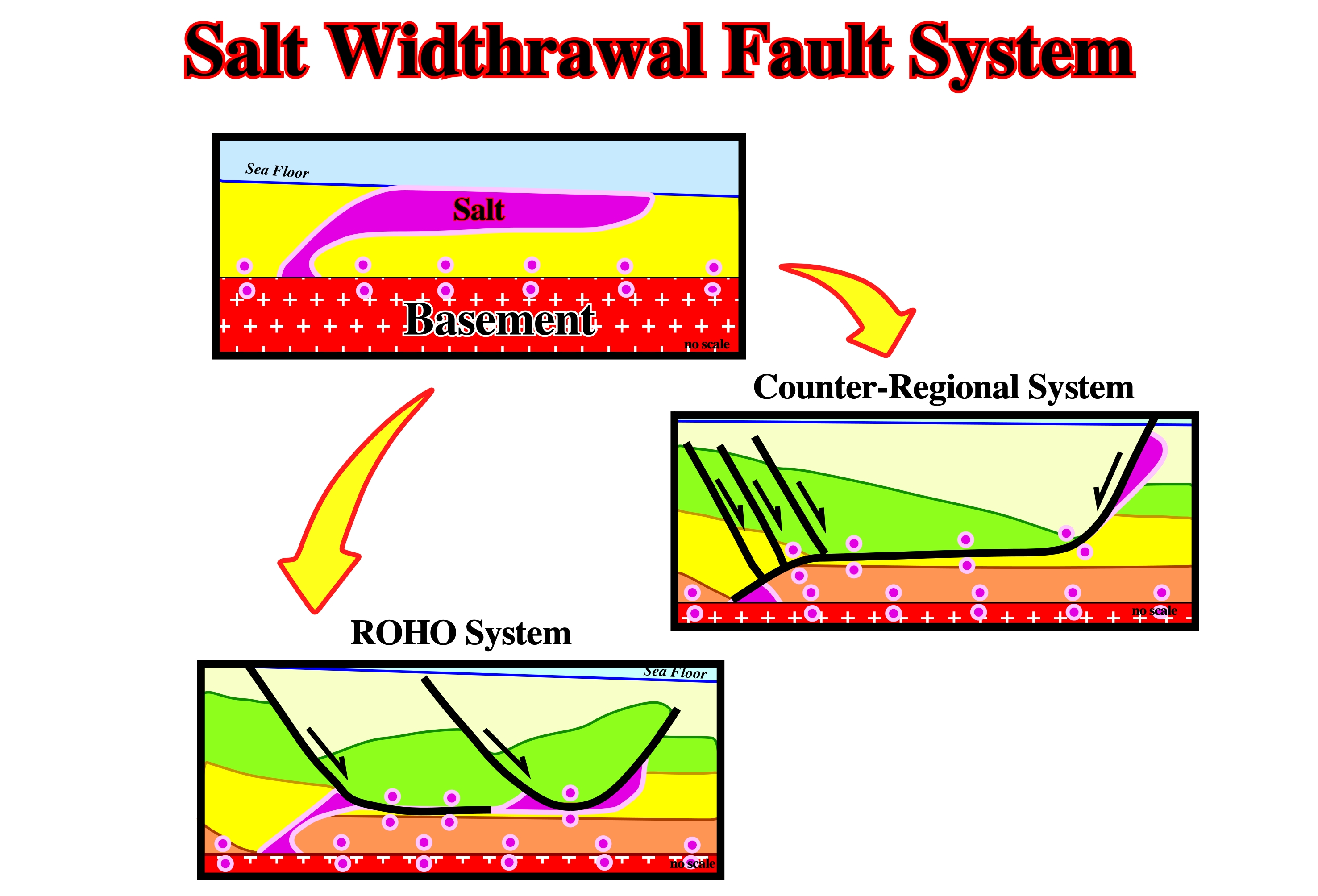
Schematic cross-section showing an allochthonous salt sheet and its ultimate evolution, following depositional loading and salt evacuation, into two end-member structural systems: (i) a stepped counter-regional system, consisting of a large growth fault looking landward, and (ii) a roho system, dominated by a major growth faults looking seaward soling into evacuated salt.
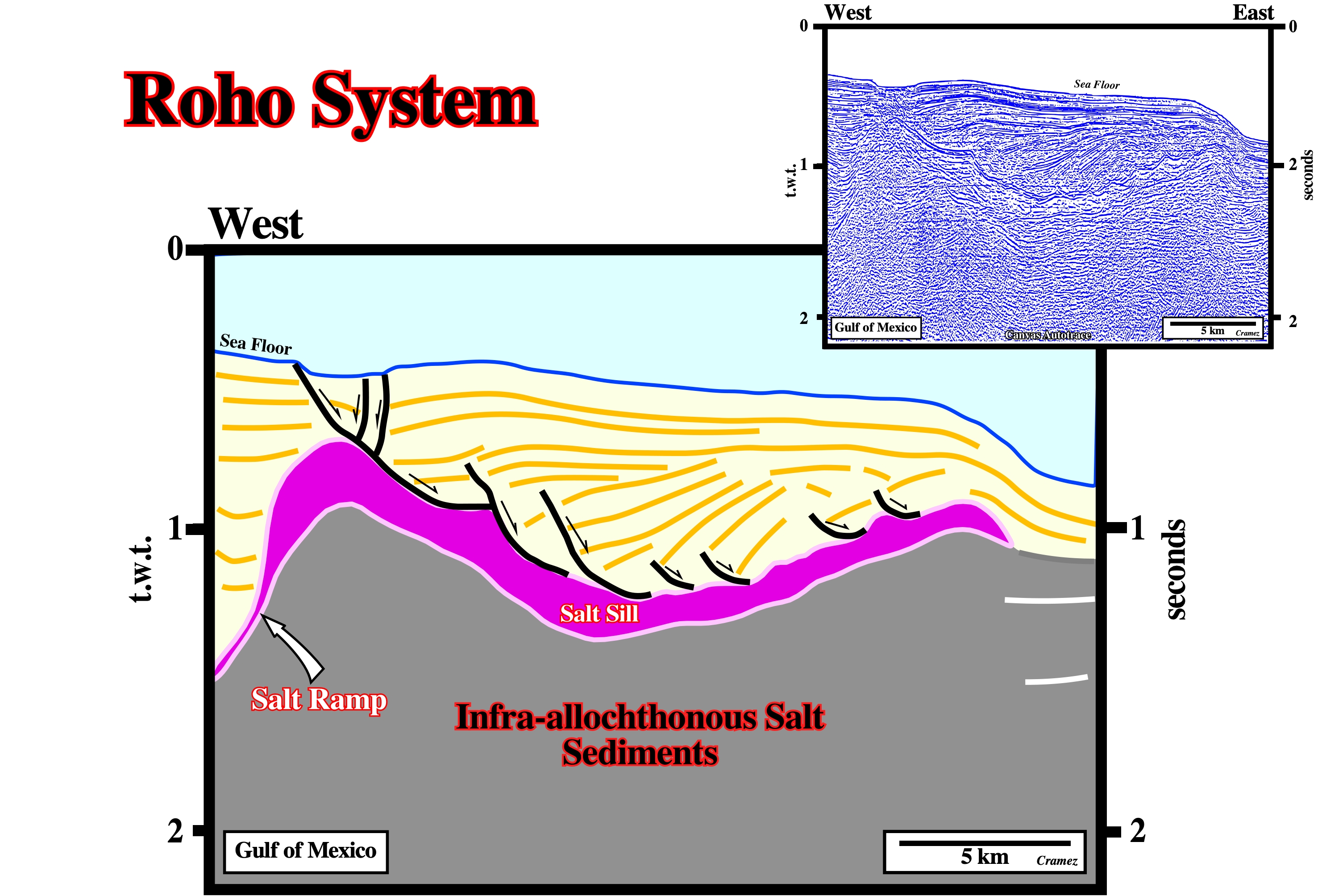
The partial evacuation of the allochthonous salt created successive depocenters, in the overlying sediments, which are limited by a series a growth-faults looking seaward. Such a fault system is call by geoscientists, particularly those working in the Gulf of Mexico, as a Roho system. Note that in this case the roho faults are not associated with tertiary salt welds.
Roller Zone
Name given by some geologists to the zone where pre-raft structures, with associated rollers, are the predominant salt structures. Typically these zones form the up-dip zones of the divergent salt margins such as the West Africa, Brazil, West Yemen, etc.
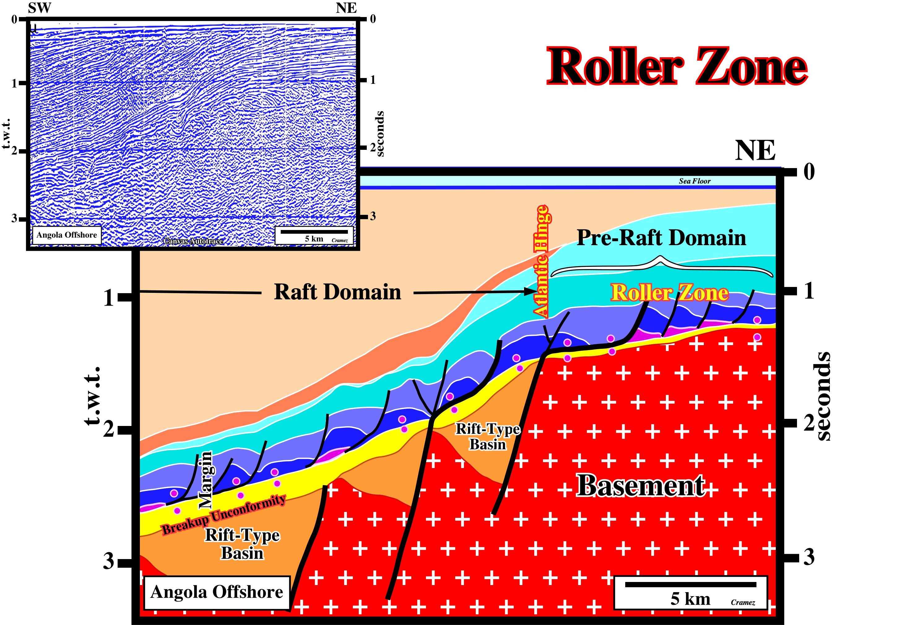
In the salt basins of the South Atlantic margins, where raft tectonics is, usually present, the location of raft and pre-raft structure is not aleatorious. As illustrated a pre-raft domain is located landward of the Atlantic hinge, while the raft realm is located seaward, where the tilt of the margin is much higher. The toplaps on the seafloor indicate uplift and erosion. Uplift took place during Late Tertiary enhancing the structural behavior. Seaward of the Atlantic hinge the dip change, extension induced rafting. The isopachous faulted blocks are disconnected, while landward, they stay more or less connected. There is no welding. The subsidence increases the extension. Therefore, large depocenters, lying on very thin salt or directly above the subsalt strata, are formed seaward of the Atlantic hinge. The Atlantic hinge is easily located. The break-up unconformity shows a sharp change in dip, as well as the tectonic disharmony. Landward of the Atlantic hinge, the extension is almost nil. The accommodation is, created, mainly by halokinesis (salt flowage), but, generally, it is insufficient to change the pre-raft geometry.
Root
Base of a diapir stem.
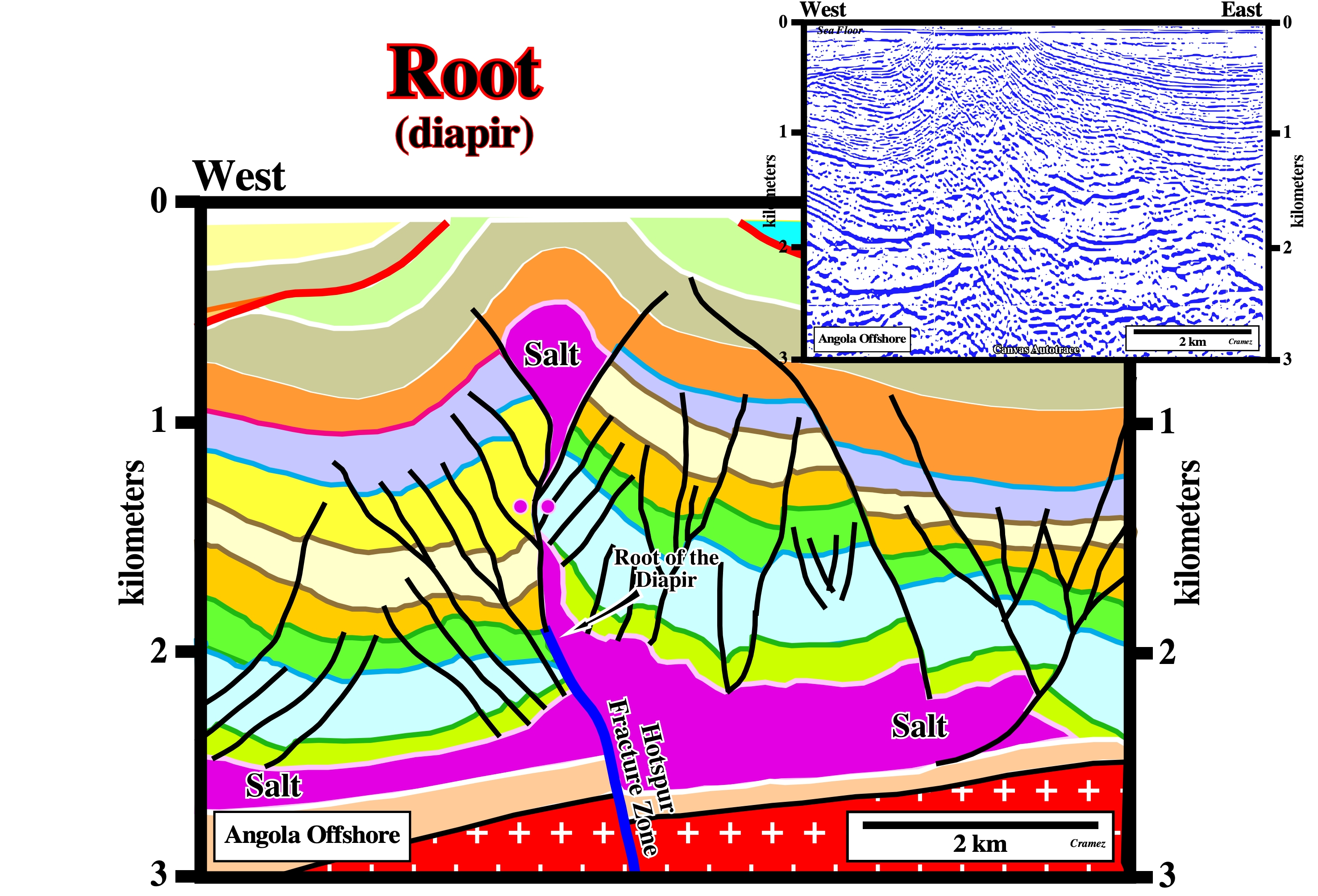
This salt structure (Cegonha Diapir) was shortened by a late reactivation of the fracture zone underline by the major fault (in blue). The normal faulting affecting the lower part of the overburden strongly contributes to the location and initiation of the salt flowage. Probably, at the onset of the overburden deposition, the fracture zone created a small salt anomaly, which initiated a local extension (normal faulting) of the overburden. The root of the salt diapir is likely associated reactivation of the fracture zone (Hotspur fracture zone, which is the northern limit of the Quenguela geological province).