
Salt Aggradation
See Aggradation
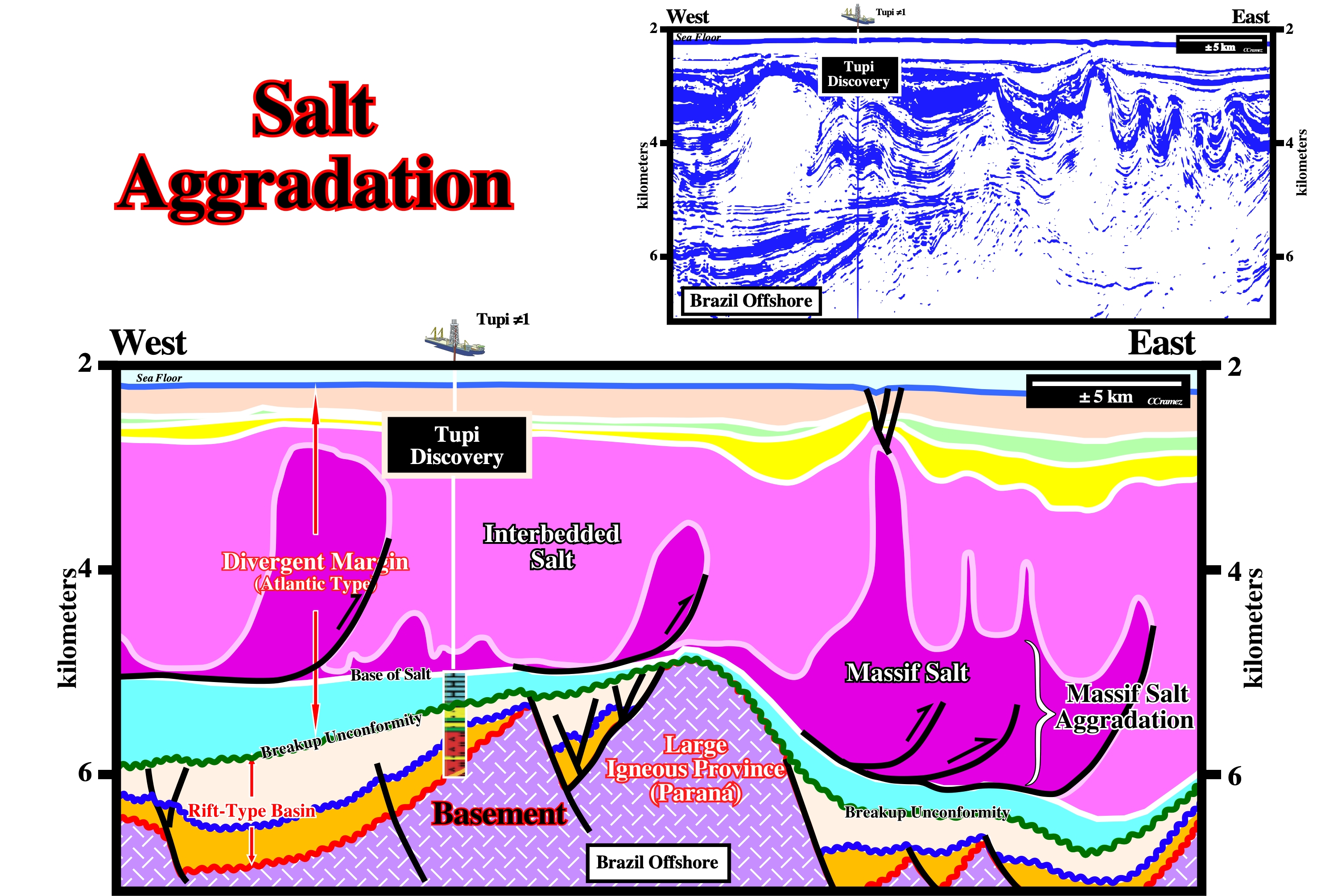
On this tentative geological interpretation of a Canvas autotrace of a Brazil offshore seismic line (Santos geographic basin), it is quite obvious to assume a salt aggradation in the eastern flank of the central buried hill of the basement (Parana volcanic rocks). On certain seismic lines, the salt onlapping is quite well visible. Such a salt aggradation implies a downward movement of the the area (eastern flank of the buried hill) after the deposition of the infrasalt margin sediments (blue interval, which postdate the breakup unconformity). It is important to note in this offshore, as well as in others (Sudan, North Sea, etc.,), that the evaporite strata can be subdivided in two intervals: (i) A massif salt interval (at the base, coloured in dark violet) and (ii) An interbedded salt interval (light violet), in which the evaporites are intercalated with clastic rocks. This means the salt induced tectonic disharmony, which underlies the bottom of the overburden, is located at the top of the interbedded salt interval and not at the top of the massif salt.
Salt Anticline
A compressional bell-shaped structure with a core of salt. Salt anticline structures are created by a compressional tectonic regime, thereof they are not synonym of salt antiforms that are created by extensional tectonic regimes.
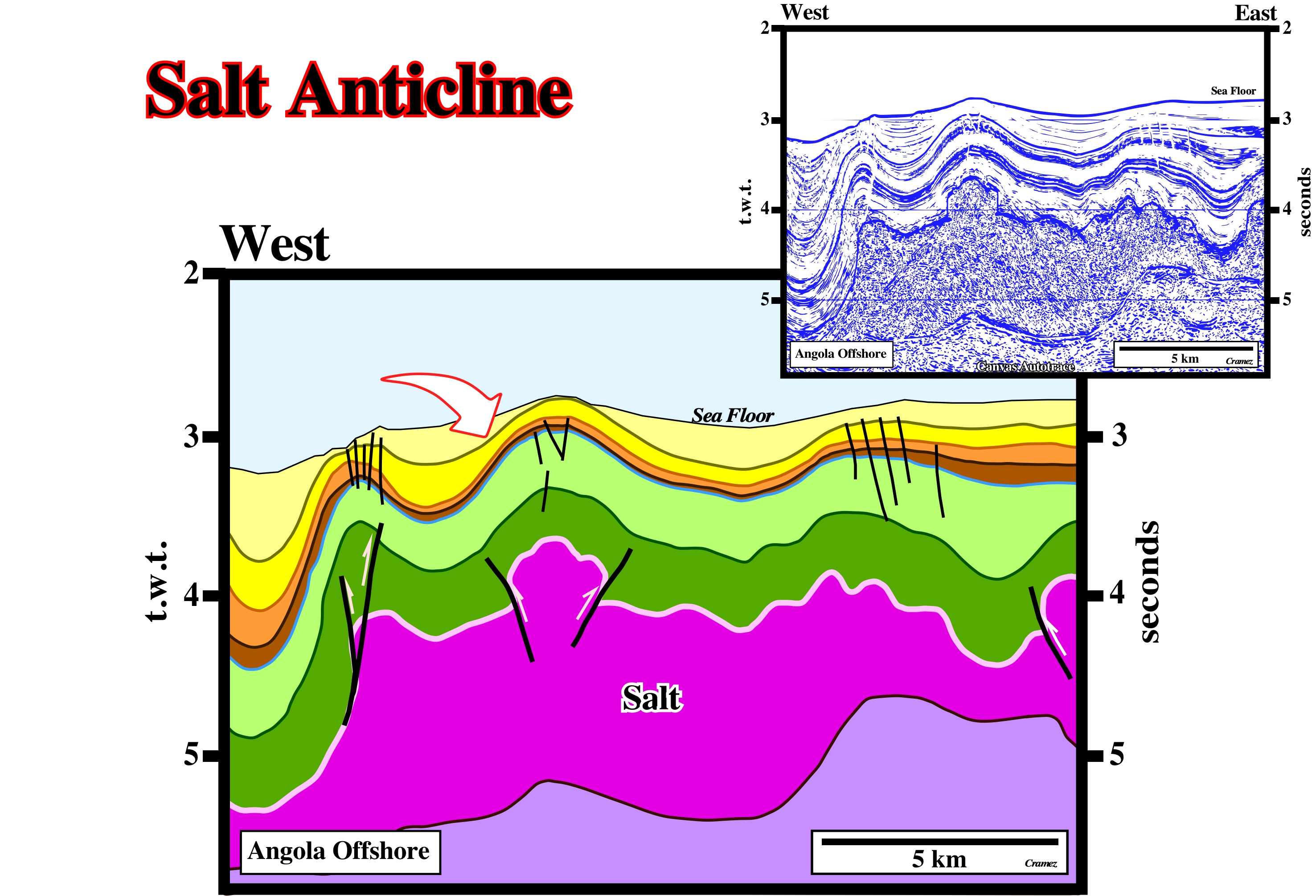
As illustrated on this tentative interpretation of a Canvas autotrace, it is quite obvious the salt layer and overburden have been shortened (shortening still is going on) by a compressional tectonic regime that some geoscientists associate with ridge pushing forces. The faults in the top of the anticline structures are strike-slip and not normal faults. Time slices between 3.0 and 3.2 seconds, strongly suggest that such faults elongate the anticline axis along the σ2 i.e., probably, they are extensional strike slip faults similar to that found long-time ago by C.E. Wegmann in Swiss Jura anticlines.
Salt Antiform
See Antiform (salt)
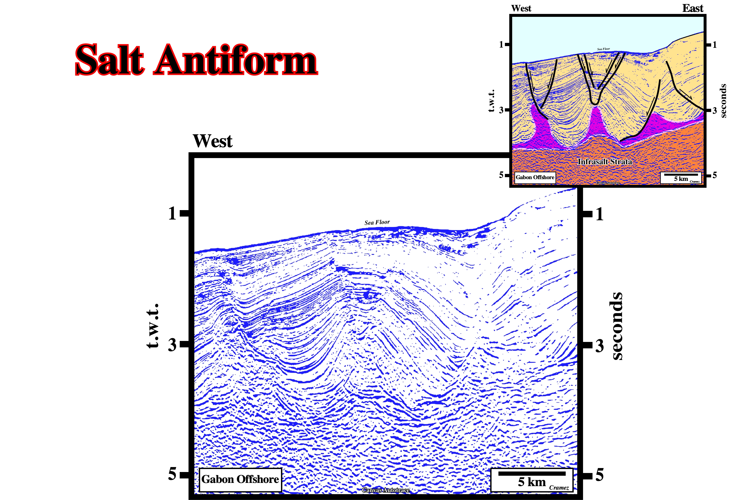
This tentative geological interpretation (Canvas autotrace of a Gabon offshore seismic line), does not refute the conjecture that an antiform is an extensional structure developed in association with an extensional tectonic regime (lengthening of the sediments) characterized by a σ1 vertical (major axis of the effective stresses ellipsoid), here with σ2 = σ3 (halokinesis). The normal faults (stretching faults) on the top of the antiform, are contemporaneous of the deformation, which is not the case in an anticline. In other words, when there are normal faults on the top of an anticline (compressional structure) the faults cannot be contemporaneous of the deformation. They postdate or predate the deformation ("tertium non datur", there is not other possibility). When they predate the deformation, they will be reactivated as reverse fault during the compressional tectonic regime creating tectonic inversions. If the reactivation is small, the null point* is located in the lower part of the fault plane and the normal geometry is, globally, conserved. On the contrary, when the reactivation is important, the null point is in the upper part of the fault plane and the reactivated fault has a reverse geometry.
* In a reactivated fault, the fault plane has a “null point”, i.e. a point with no apparent displacement: (i) (i) Above the “null point”, the fault has a reverse geometry ; (ii) Below the "null point", the geometry of the fault is normal, in spite of fact that the fault is reverse. Its last movement was reverse, but not enough to change the geometry.
Salt Basins (Jackson, M.P.A. and Talbot, C.J, 1991)
The map below showing the distribution of the salt structures, depicts only those parts of salt basins where deformation is large enough that salt structures are prominent on reflection seismic profiles. Areas of undeformed salt are not shown.
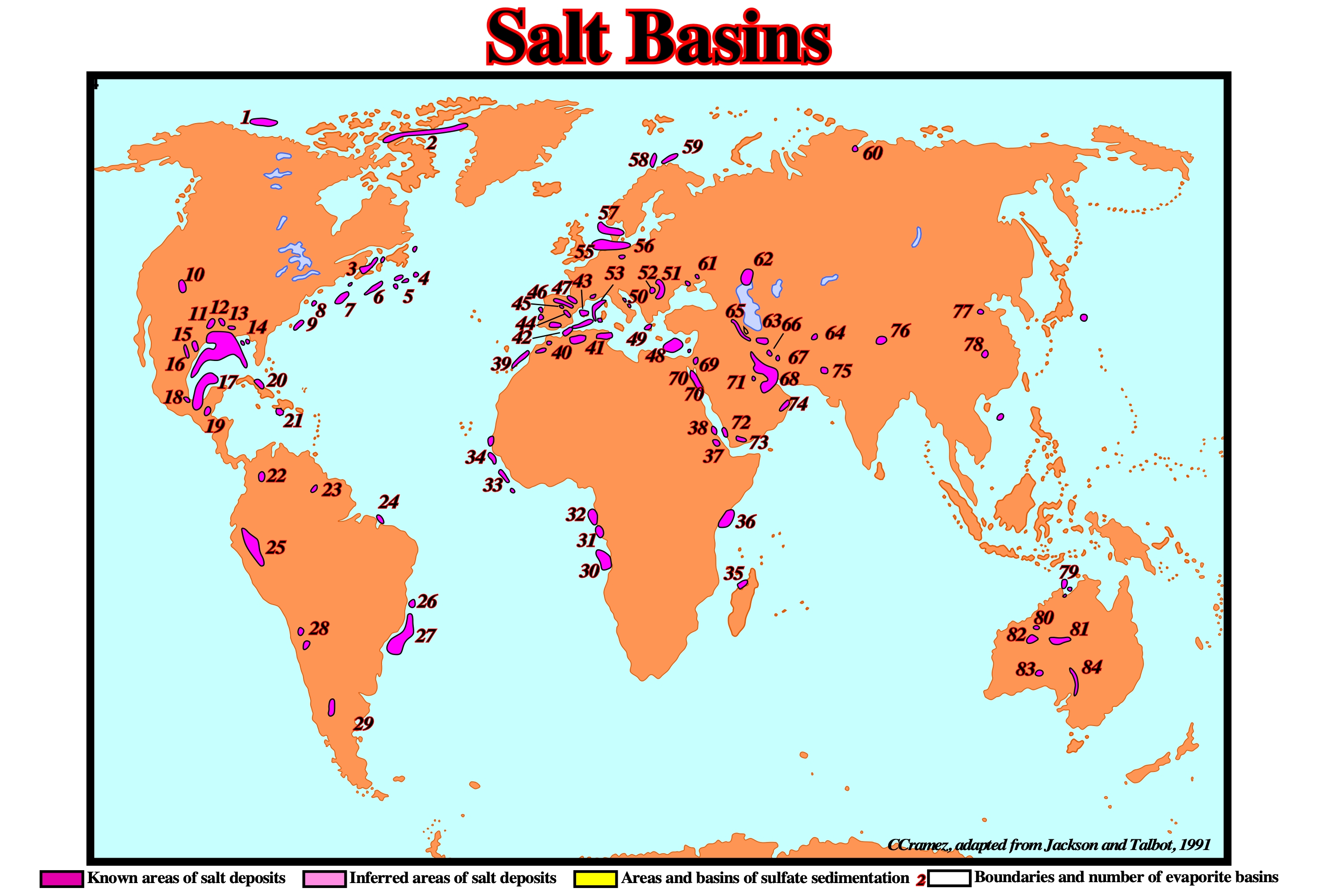
Salt provinces are categorized by amount of petroleum production according to AAPG's classification of sedimentary provinces of the world (St. John and others, 1984. A) Giant: (2) Sverdrup ; (4) Jeand'Arc ; (5) Grand Banks ; (10) Paradox ; (11) East Texas ; (12) North Louisiana ; (14) Gulf Coast, (18) Salinas ; (22) Zipaquira ; (31) Cabinda ; (32) Gabon ; (47) Aquitaine ; (55) Southern North Sea ; (56) Northwest German ; (57) Northern North Sea ; (58) Tromso ; (61) Dnepr-Donetz ; (62) North Caspian ; (64) Tadjik ; (68) Zagros ; (70) Suez ; (71) Arabian ; (72) Red Sea East ; (74) Oman. B) Subgiant: (6) Scotian ; (13) Mississippi ; (16) Sabinas ; (19) Petenchiapas ; (23) Takutu ; (25) Oriente-Ucayali ; (26) Espirito Sant ; (27) Campos ; (30) Kwanza ; (39) Essaoira ; (40) Atlas ; (41) Pelagian ; (46) Cantabrian ; (49) Ioninan ; (50) South Adriatic ; (51) Carpathian ; (52) Transylvanian ; (63) Great Kavir) ; (77) Bohai Bay ; (79) Bonaparte ; (80) Canning ; (81) Amadeus. C) Nonproductive: (1) Chukchi ; (3) Moncton ; (7) Georges Bank ; (8) Baltimore Canyon ; (9) Carolina ; (15) South Texas ; (17) Sigsbee ; (20) Cuban ; (21) Haitian ; (24) Barreirinhas ; (28) Atacama ; (29) Neuquen ; (33) Liberia ; (34) Senegal ; (35) Comores ; (36) West Somali ; , (37) Danakil ; (38) Red Sea West ; (42) Algerian-Alboran ; (43) Balearic ; (44) Ebro ; (45) Jaca ; (48) Levantine ; (53) Ligurian ; (54) Rhodania ; (59) Nordkapp ; (60) Yenisey-Khatanga ; (65) Tabriz ; (66) Yazd-Kalut ; (67) North Kerman ; (69) Dead Sea ; (73) Hadhramaut ; (75) Salt range ; (76) Qaidam ; (78) Jianghan ; (82) Woolnough ; (83) Officer ;(84) Flinders.
Salt Budget
The lost of salt by dissolution. Goguel's law (during deformation the volume of sediments is kept roughly constant) is difficult to apply to salt layers. Actually, the salt budget suggests that dissolution take almost always place and it can reach 30% of the total salt volume. In Gulf Coast, some geologists estimate that a minimum of 6 km 3 of salt was dissolved into present formation waters.
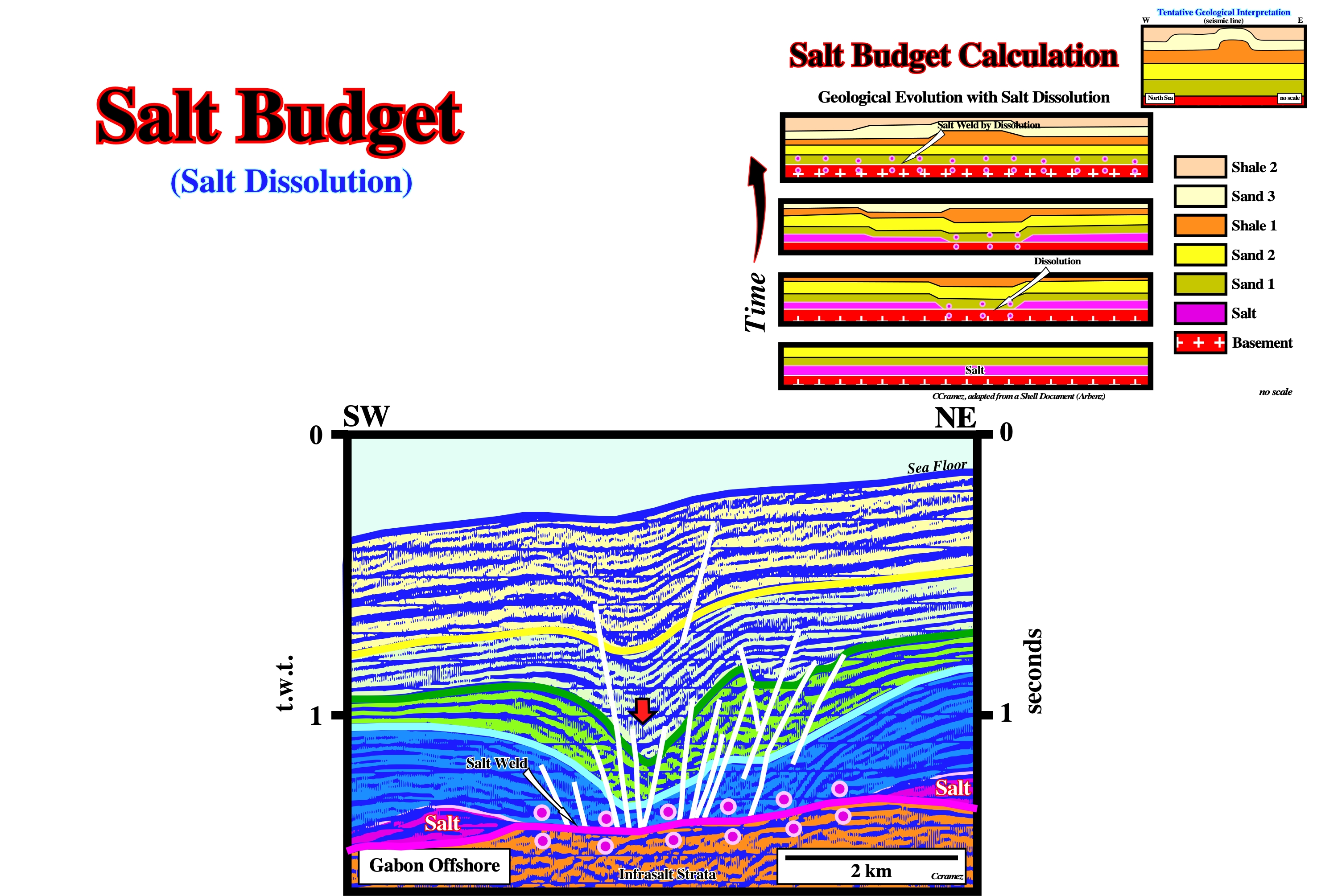
Taking into account the normal faulting system (accommodation faults) on this tentative geological interpretation of Canvas autotrace of a Gabon offshore seismic line, salt dissolution is, probably, the major reason of the overburden collapse. It that is true, the salt budget calculation can be approached by palinspathic restorations similar to that done to a North Sea seismic line by Arbenz (1970, ?), illustrated above (upper right corner).
Salt Bulb
A salt protuberance induced by lateral salt flowage. A salt bulge can became a diapir. See: Downward Salt Bulge.
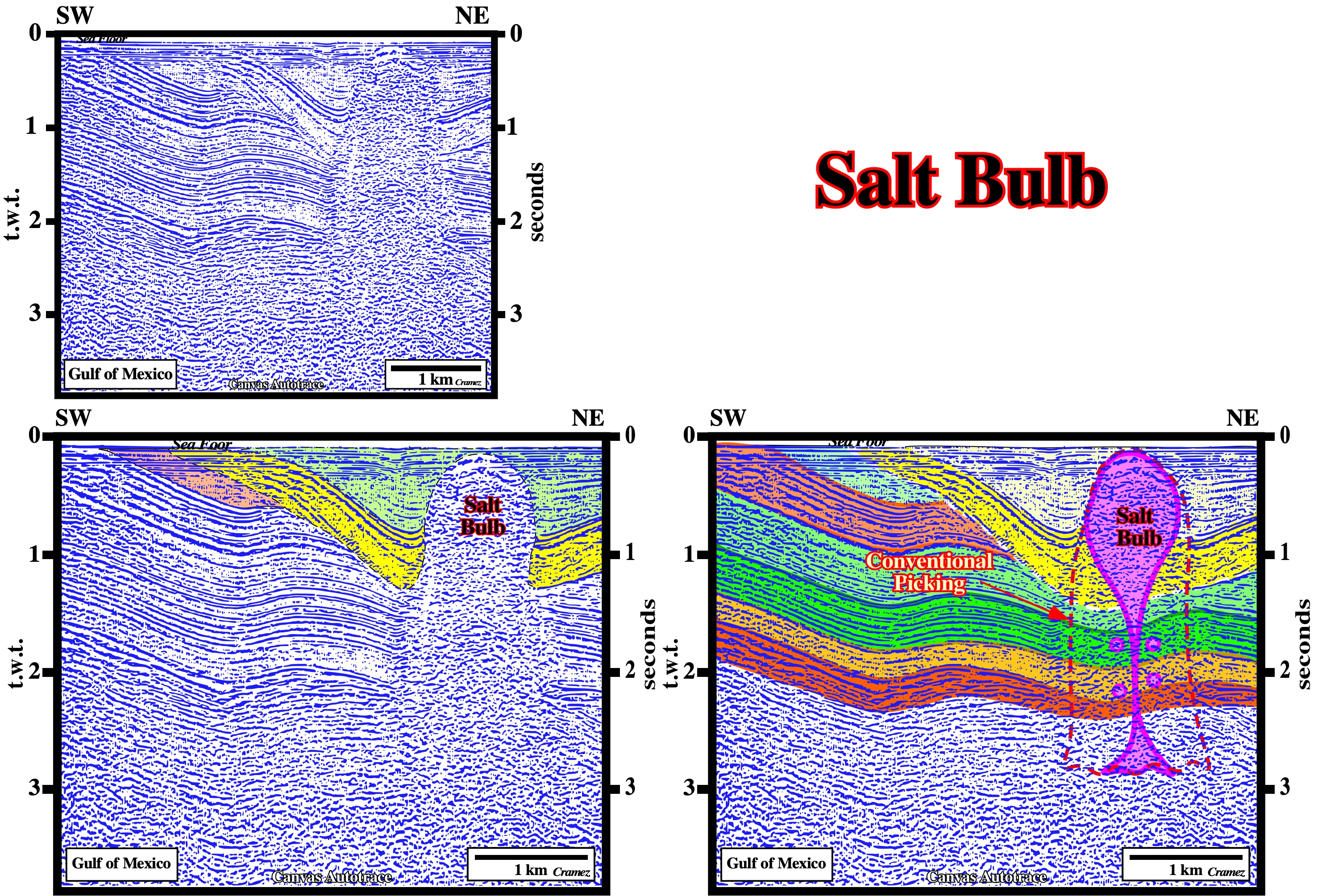
Salt bulbs were interpreted in quite different way. When I was a young geoscientist, the majority of them were interpreted as salt domes with more or less vertical flanks. Sooner, the geoscientists understood that such naive interpretation was a physical impossibility. The bottom of salt diapir was much deeper than the basin bottom (see Salt Canopy). The density of the salt is, roughly, constant in depth. It varies between 2,15 and 2,17 depending in the presence of certain elements, as magnesium, for instance. The salt is not compactable in depth, what is not the case of the other rocks. In the evolution of a salt dome there is always an inversion point, below which the salt is less denser than adjacent rocks or above which the adjacent rocks are less denser that the salt. Such a priori conditions suggest another picking of the flanks of a salt structures (hypothetical deductive interpretation) with a bulb in the upper part and a stem between the bulb and the autochthonous salt layer as illustrated above.
Salt Canopy
Composite diapiric structure formed by partial or complete coalescence of diapir bulbs or salt sheet. These coalescence bodies may or may not be connected to their source layer.
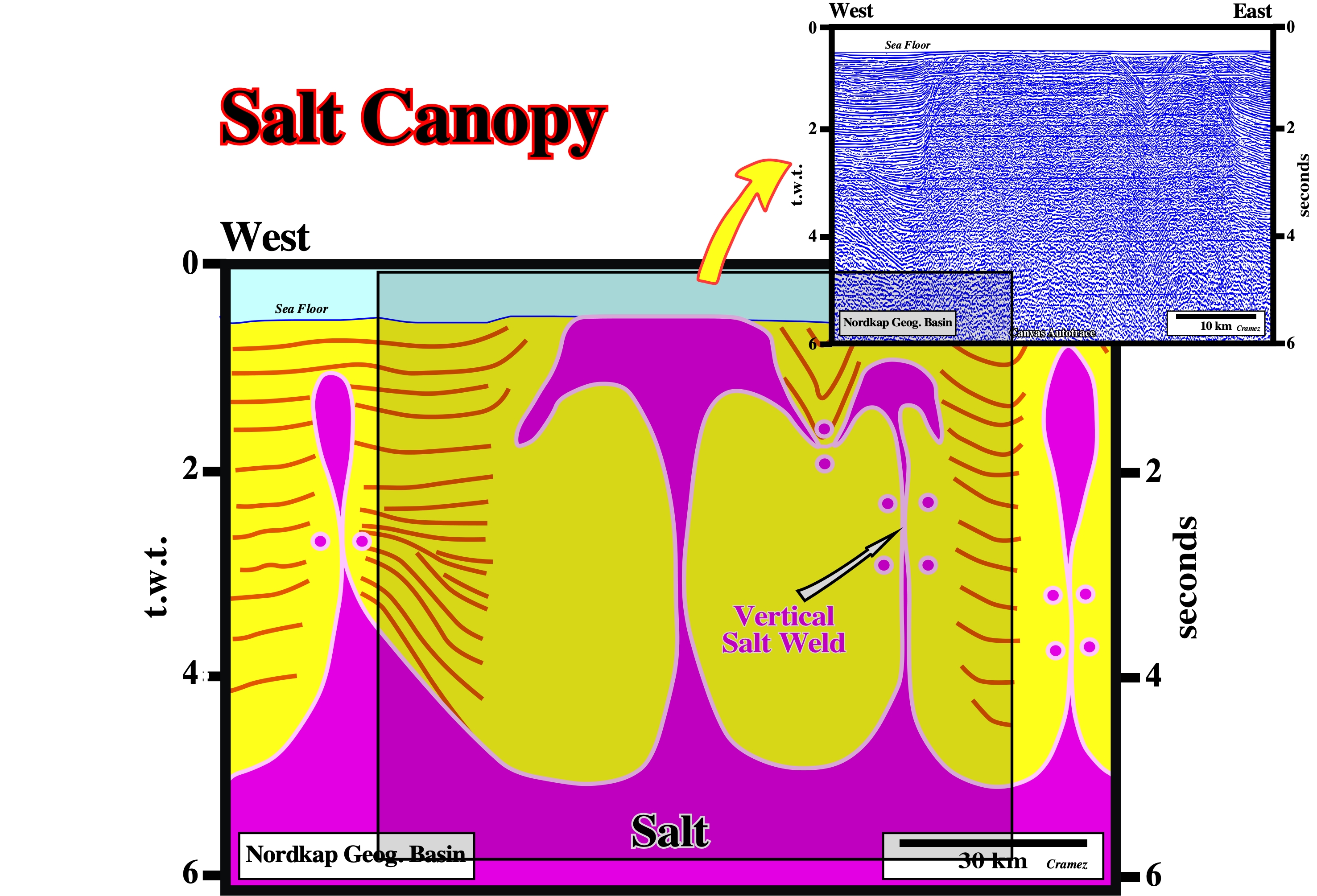
This tentative interpretation takes into account the Rayleigh-Taylor instability. During long-time, in this area (Nordkapp geographic basin), erroneously, large diapiric structures (>30 km wide) were assumed and were even proposed to keep radioactive waste. With such large salt structures with the top near the sea floor (some of them outcropping) and the bottom quite deep, a simple depth conversion falsify the assumed phallic geometry with almost vertical flanks. In depth, the bottom of such structures was 3-4 times deeper than the bottom of the basin. Tentative geological interpretations, as the one illustrated above (Canvas autotrace of a Nordkapp geographic basin seismic line), with salt canopy structures are much difficult to refute and, strongly, change the geometry of the salt structures as well the petroleum potential, at least the trapping parameter.
Salt Collapse
Synonym of Salt Withdrawal.
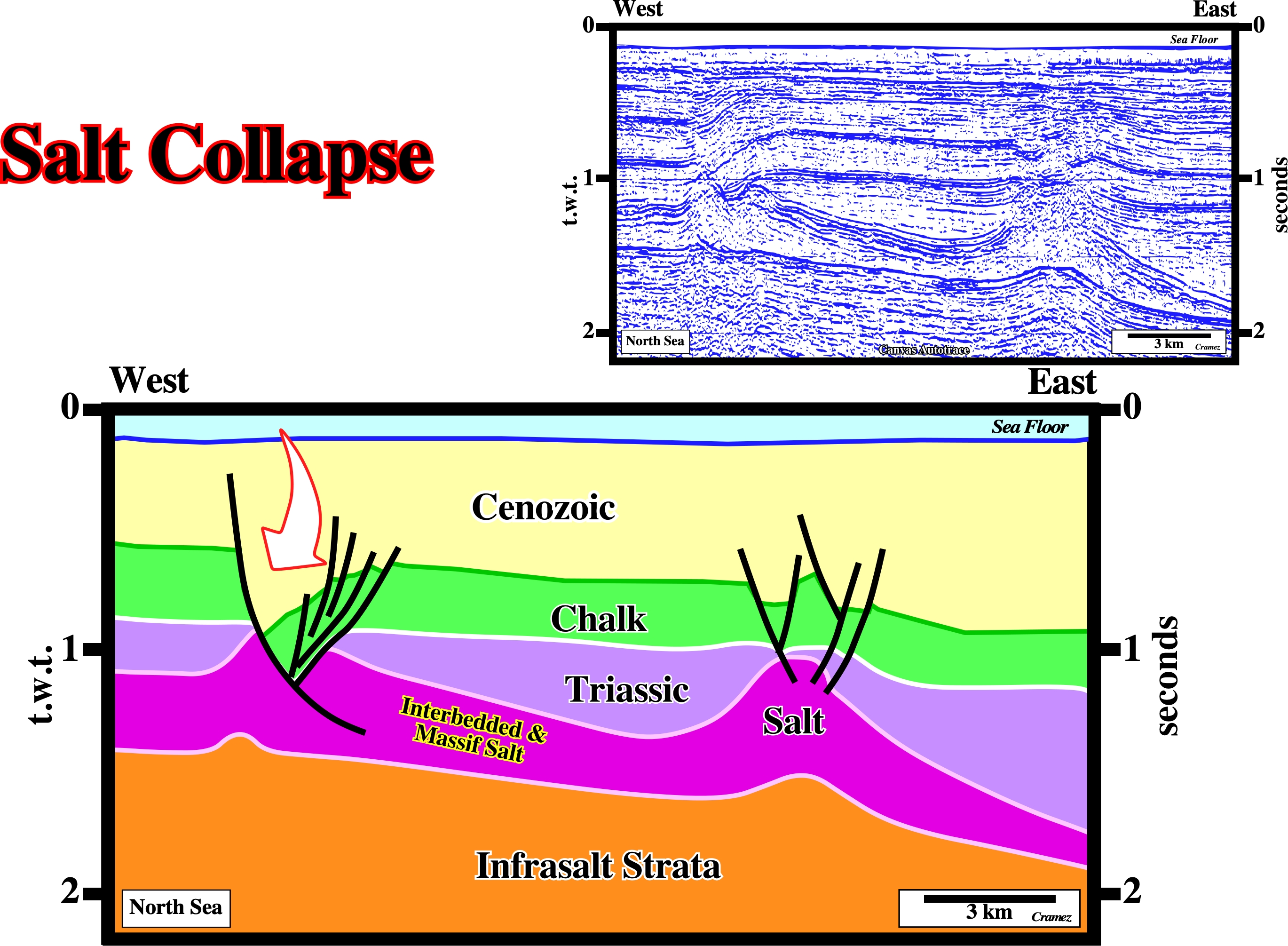
The normal faulting developed on the top of the salt antiforms can be explained by salt withdrawal or salt collapse. The faulting affects not only the overburden by the salt as well, particularly, the layers of salt interbedded with clastic sediments (interbedded salt). This means that, at least, the upper part of the salt interval is composed by salt interbedded with others clastic rocks, while the low part is formed, mainly, by massif salt. The salt collapse began at the Cenozoic what explains the Cenozoic depocenters (thickness increasing of the hangingwall of certain normal faults).
Salt Decollement
Tectonic disharmony or detachment surface associated with a salt layer either autochthonous or allochthonous.
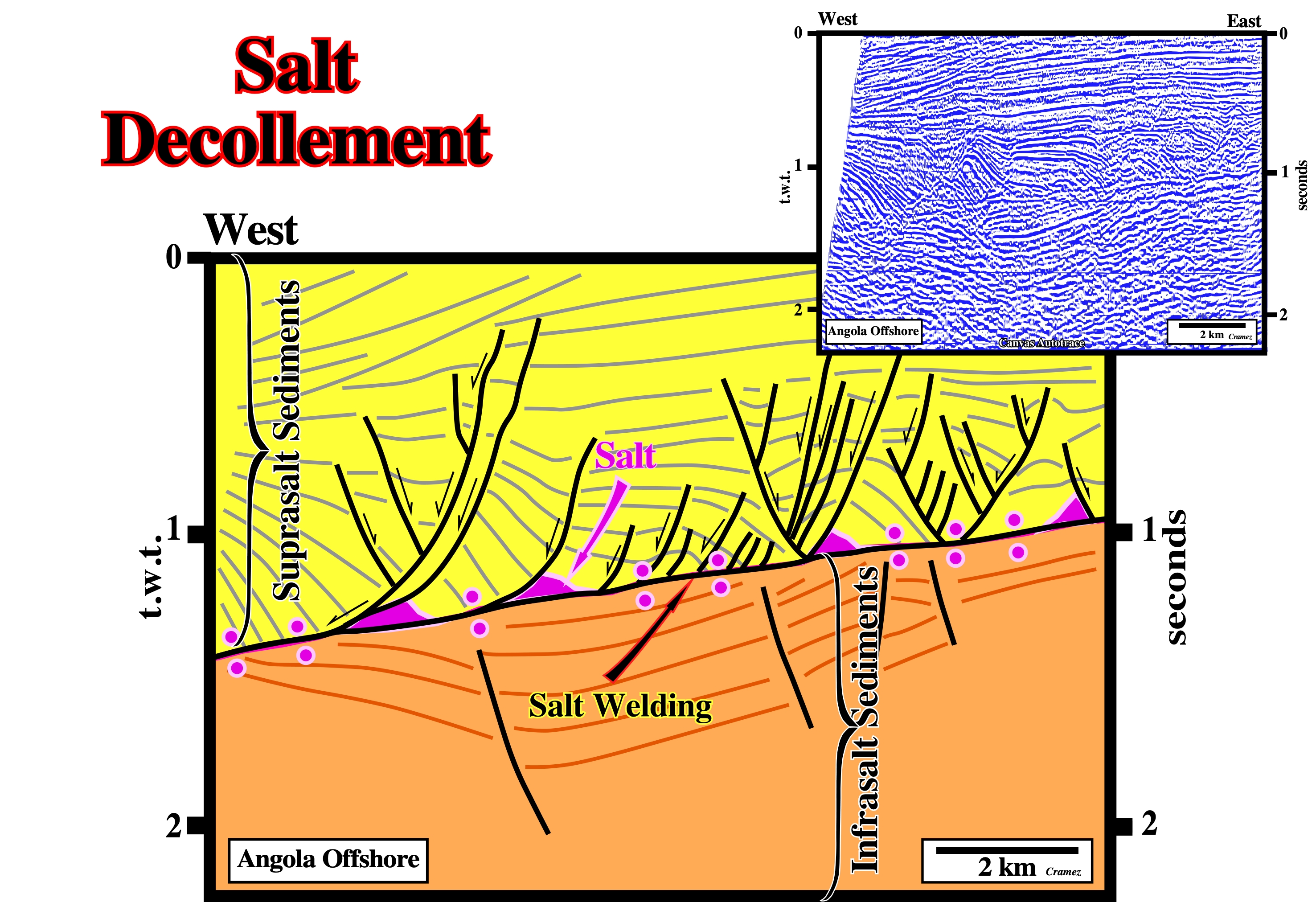
The primary salt weld recognized in the central part of the the line emphasizes the tectonic disharmony associated with the bottom of the salt layer, which can be considered as a decollement surface. The overburden and subsalt strata show quite different deformations. Salt roller are recognized on the bottom of pre-raft structures. The subdivision of the sedimentary column in suprasalt (or overburden sediments) and infrasalt or subsalt strata has no geological meaning in terms sedimentary basin classification (realm of subsidence). It is just a stratigraphic division in relation to the allochthonous salt layer. The breakup unconformity is located within the infrasalt (subsalt) sediments, which can encompass : (i) Basement sediments, as when the basement is a Paleozoic folded belt, for instance ; (ii) Rift-type basin sediments and (iii) Margin sediments (infrasalt margin sediments).
Salt Diapir
Synonym of Diapir or Salt dome.
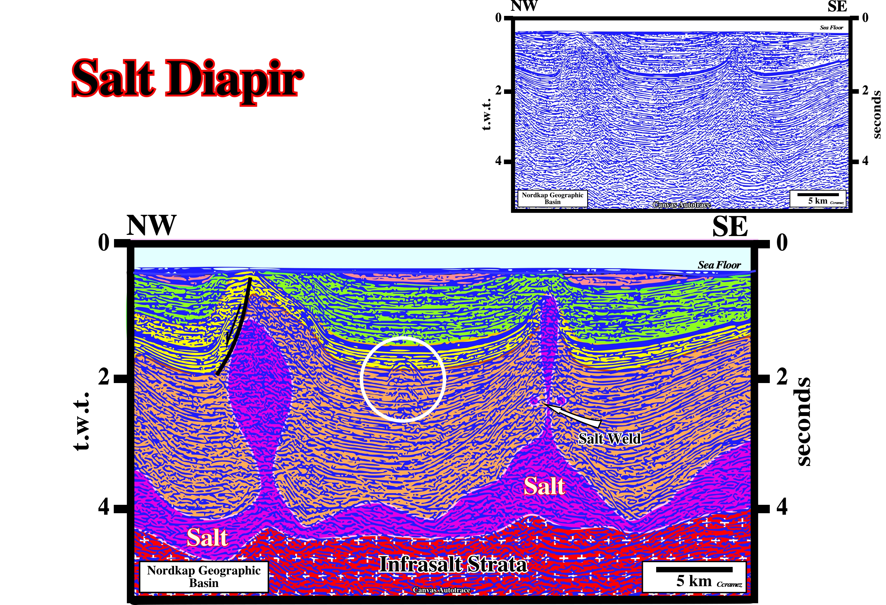
Salt diapirs are frequent in Nordkap geographic basin. On this tentative geological interpretation of a Canvas autotrace of a seismic line shot in this area. The great majority of these salt diapir (salt domes) were interpreted on the old unmigrated seismic lines as having vertical flanks. Sooner, the geoscientists realize such naive inductive interpretations were, easily, falsified. The salt density is, more or less constant, in depth (salt is not compactable), which is not the case of the rocks forming the overburden. Different tentative interpretations were proposed, as those illustrated above, which are more difficult to refute. In certain case the allochthonous salt is, completely, disconnected from the mother salt layer (autochthonous salt) with formation of a, more or less, vertical salt welds (secondary salt weld). On the sea floor, the truncation of the overburden sediments induced by the uplift created by diapirism is quite interesting. However it should not be taken as a general but a particular geological event. Truncation is, generally, associated with a relative sea level fall during which the erosional agents create an erosional surface, i.e. an unconformity, which is not necessary associated with a shortening or a lengthening of the sediments. If the shortened or lengthened sediments do not outcrop, there is no relative sea level fall and so there is no truncation or unconformity. The eustatic changes create unconformities, not the tectonic changes. The white circle, on the autotrace (migrated Nordkapp seismic line) suggests the presence of an iceberg, at the time of the shooting, not far from the shooting line (± 1,500 meters).
Salt Disharmony
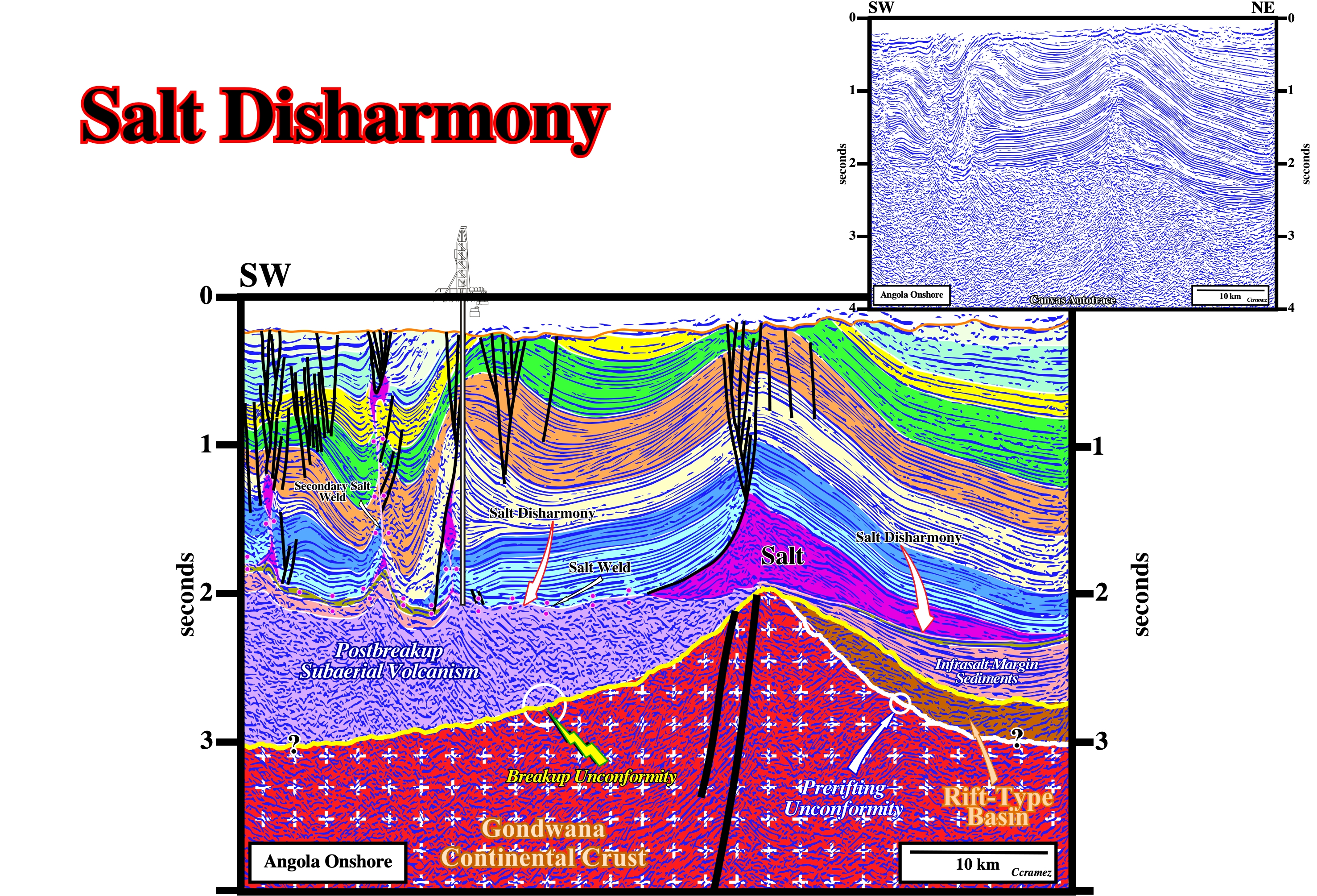
On this tentative geological interpretation of a Canvas autotrace of a seismic line of the Kwanza onshore geographic basin (Angola onshore), the deformation contrast between the overburden and the subsalt strata is is quit sharp. The cover (salt + overburden) is deformed by halokinesis, while the subsalt strata is, mainly, undeformed. The overburden was uplifted and eroded, partially, in surface creating a sharp erosional surface. The interface between the cover and the subsalt strata marks the salt induced tectonic disharmony. The lengthening of the overburden induced obvious antiform structures with associated typical coeval normal faults. There is only one way to length the sediments, i.e, by normal faulting. The breakup unconformity (picked here in yellow) separates rift-type sediments (in brown) striking, roughly, parallel to the trace of the seismic line, from infrasalt (or subsalt) margin sediments (in beige) or from postbreakup subaerial volcanism (recognized by the exploration well), in the left part of the autotrace.
Salt Dissolution
See: Dissolution and Salt budget.
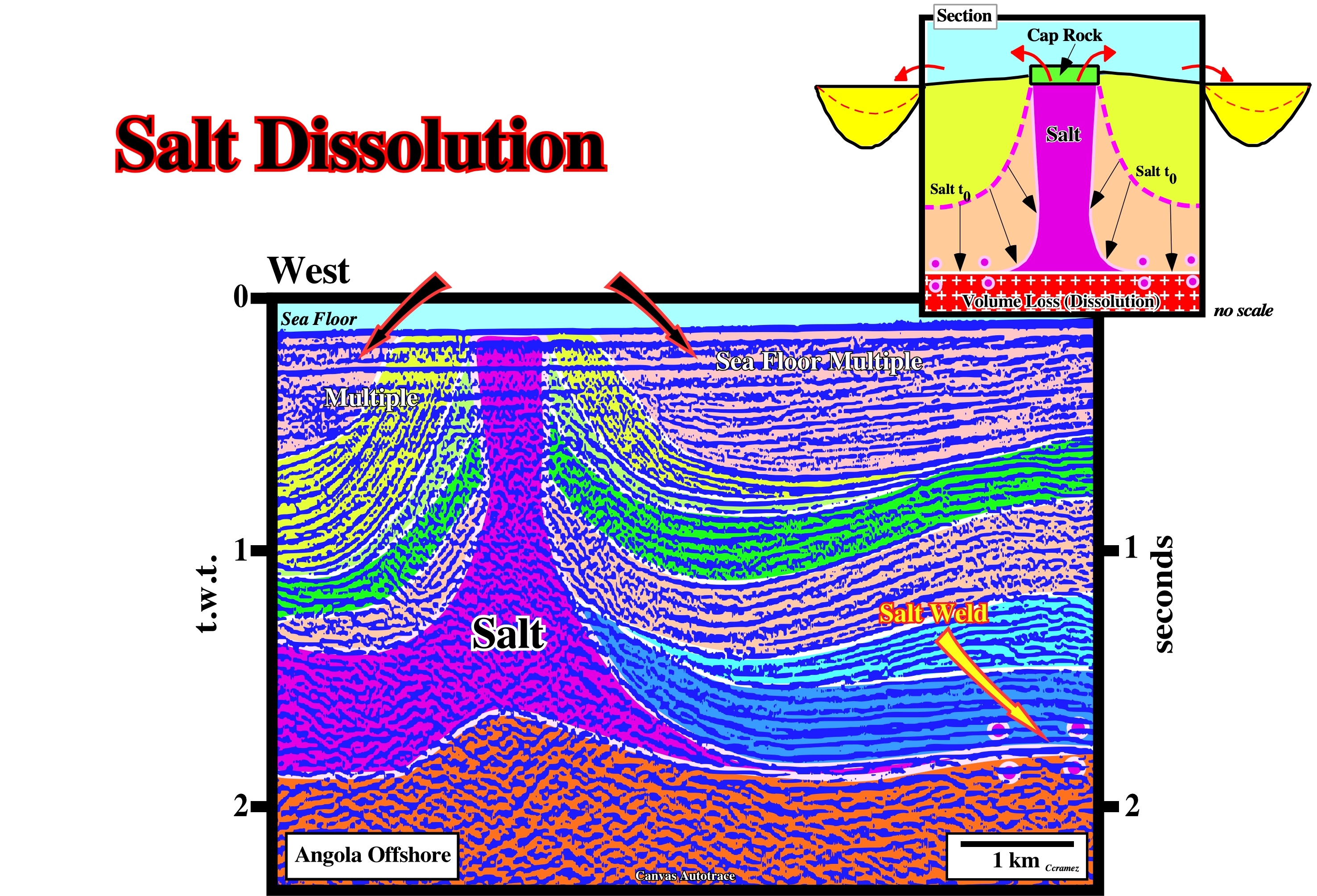
Since the uplifted and lengthened overburden sediments arrive at sea floor due to halokinesis, as it is the case on this tentative geological interpretation of a Canvas autotrace of an Angola offshore seismic line, they are truncated by the erosional agents creating clear toplap geometrical relationships (the presence of a multiple of the sea floor masks, slightly, the toplapping evidence). Since the salt diapir arrives at the sea floor, the cap rock and the rock salt are not only eroded, but partially dissolved as well. The eroded material becomes a source of terrigeneous supply to the filling of the the adjacent depocenters, as suggested in the geological sketch.
Salt Dome
Imprecise term for a domal upwelling comprising a salt core, which may or may not be diapiric (i.e. discordant), and an envelope of deformed overburden. Synonym of diapir and salt diapir.
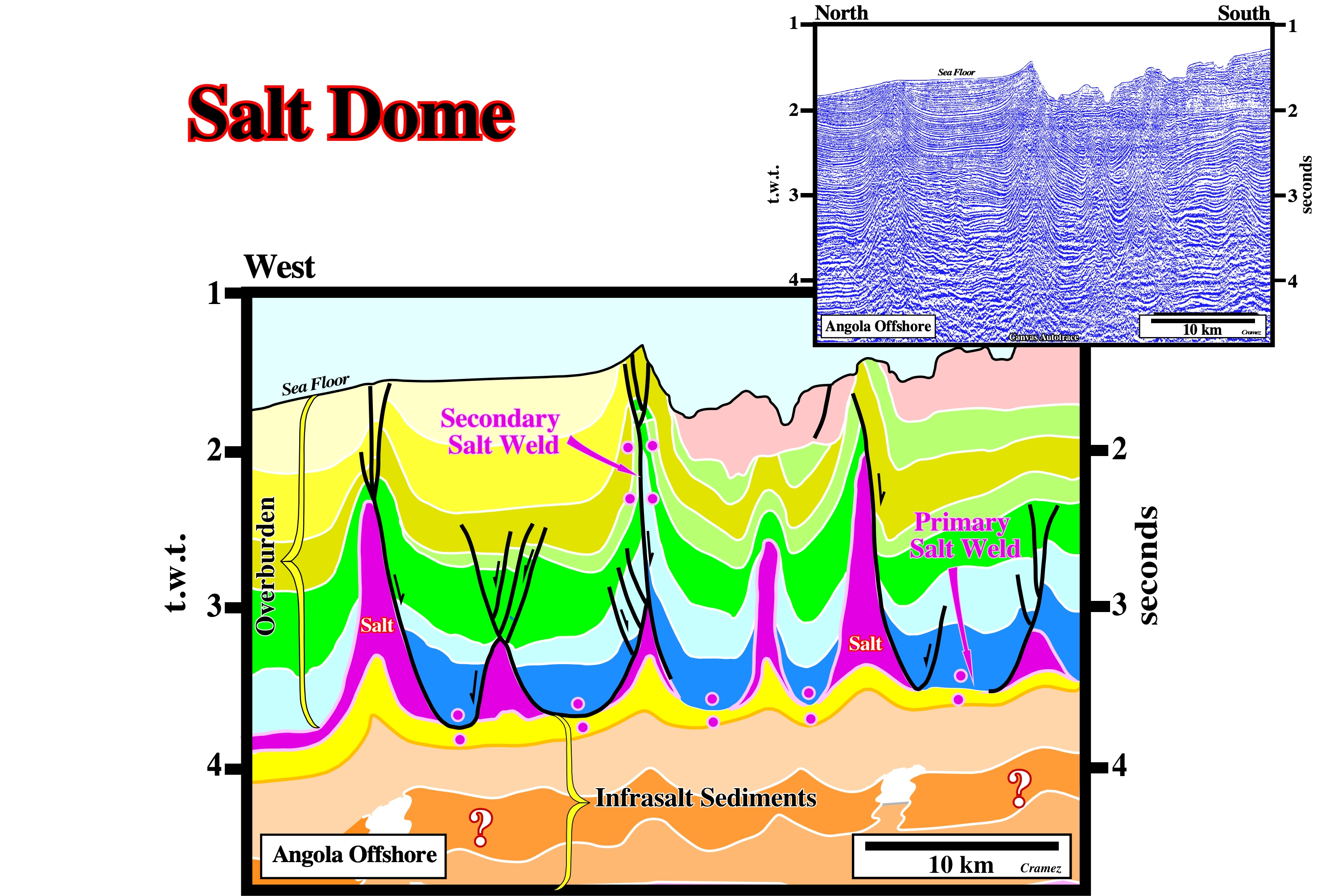
On this seismic line, the overburden is quite deformed, while the subsalt strata is mainly undeformed. The undulations of the subsalt strata are apparent. They correspond to seismic pitfalls. They are induced by lateral changes in the velocity of the cover (salt + overburden). At the vertical of each salt dome, the subsalt strata are pulled-up or pulled-down (see the bottom of the salt or top yellow interval). The majority of the salt domes is disconnected of the mother source layer by primary salt welds. In the central part of the tentative interpretation a secondary (vertical) salt weld is quite possible, taking into account the seismic resolution.
Salt Drop Structure
Synonym of Detached salt stock.
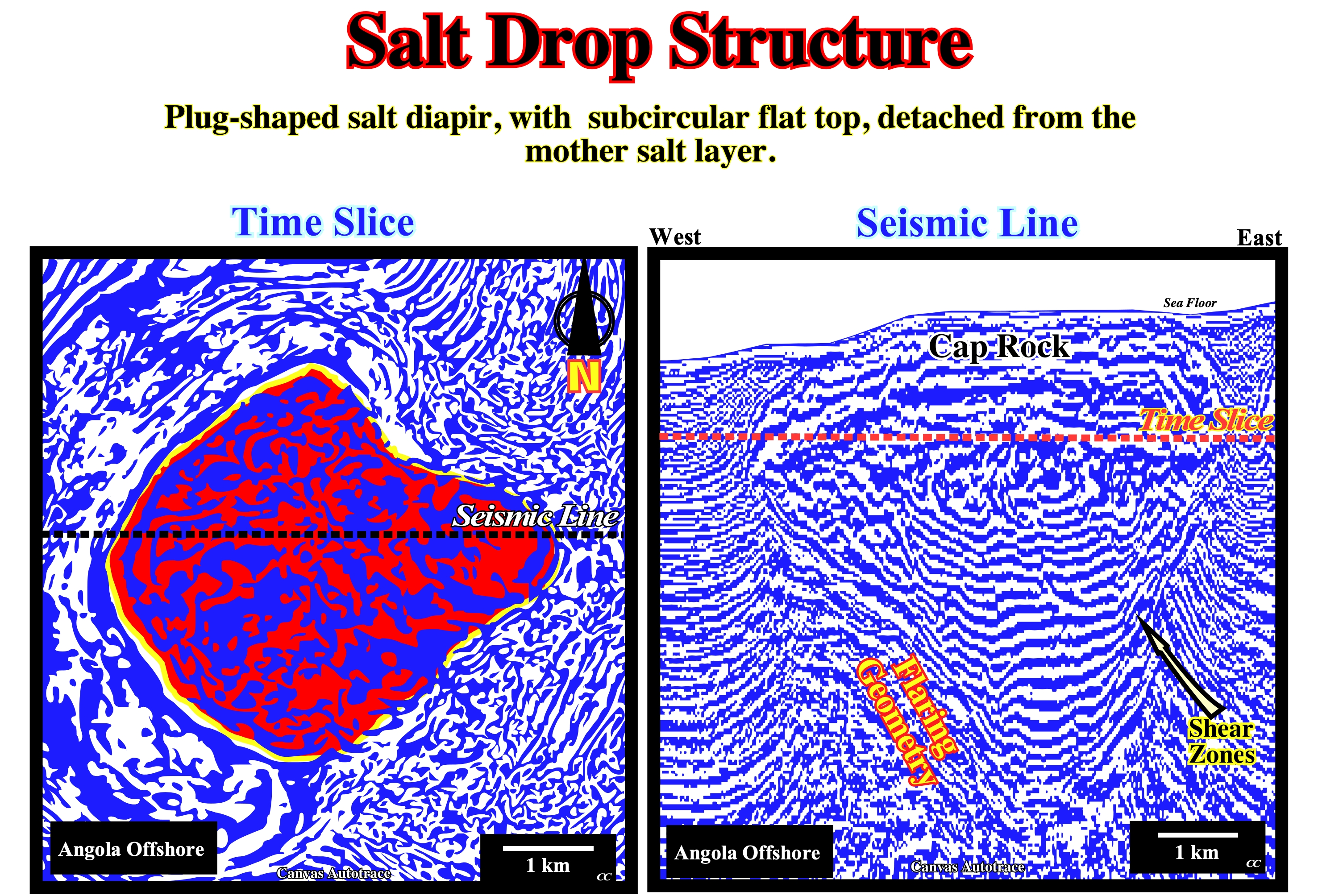
The salt structure recognized on the above Canvas autotraces corresponds to a salt drop structure (also called detached salt stock). It is disconnected from the allochthonous salt by a secondary salt weld (not visible on the seismic line autotrace, which is not deep enough). The top of the salt diapir is flat and more or less circular (take into account the cap rock). On the autotrace of the seismic line, the flaring geometry is quite evident, what means that the flow rate of the salt minus dissolution divided by the aggradation rate minus compaction ranges between 100> R°/A°>10 . Internal shear zones (band of highly deformed rock separating two rock masses that have sheared pas each others) are easily recognized on the flanks of the salt drop structure.
Salt Evacuation
A total flowage or withdrawal of the salt layer. In absence of significant extensional tectonic regime, a salt evacuation induces a lengthening of the the overburden. Thus, a salt evacuation of a roller induces a lengthening of the footwall sediments creating an apparent reverse-fault (a normal fault with a reverse geometry).
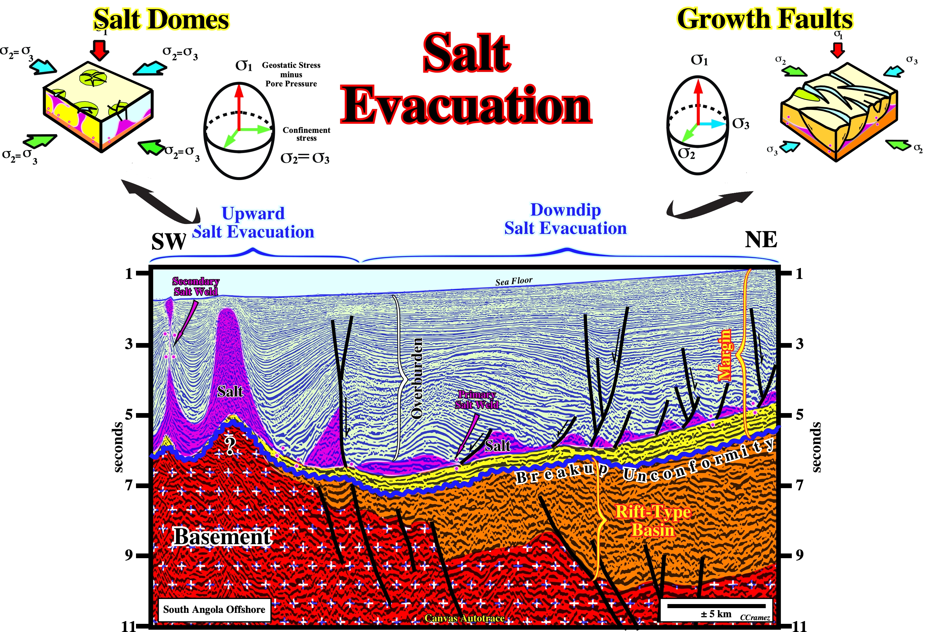
The salt can evacuate or flow vertically (diapirism), downdip or up-dip depending on geological conditions. On this tentative geological interpretation of a Canvas autotrace of an Angola offshore seismic line, on which a rift-type basin sediments (colored in brown), the breakup unconformity, in blue, and the subsalt margin sediments (colored in yellow) are quite well recognized. The bottom of the salt, which emphasize the salt tectonic disharmony and along which the salt flowed downdip with the formation of small growth-faults with a SW vergence. Above the basement buried hill, the salt flowed vertical developing a salt dome with a taper geometry and a salt drop structure (detached salt stock) and a secondary (vertical) salt weld.
Salt Evacuation Surface (Diegel, F. A. et al, 1995)
Synonym of Salt weld or Salt withdrawal surface.
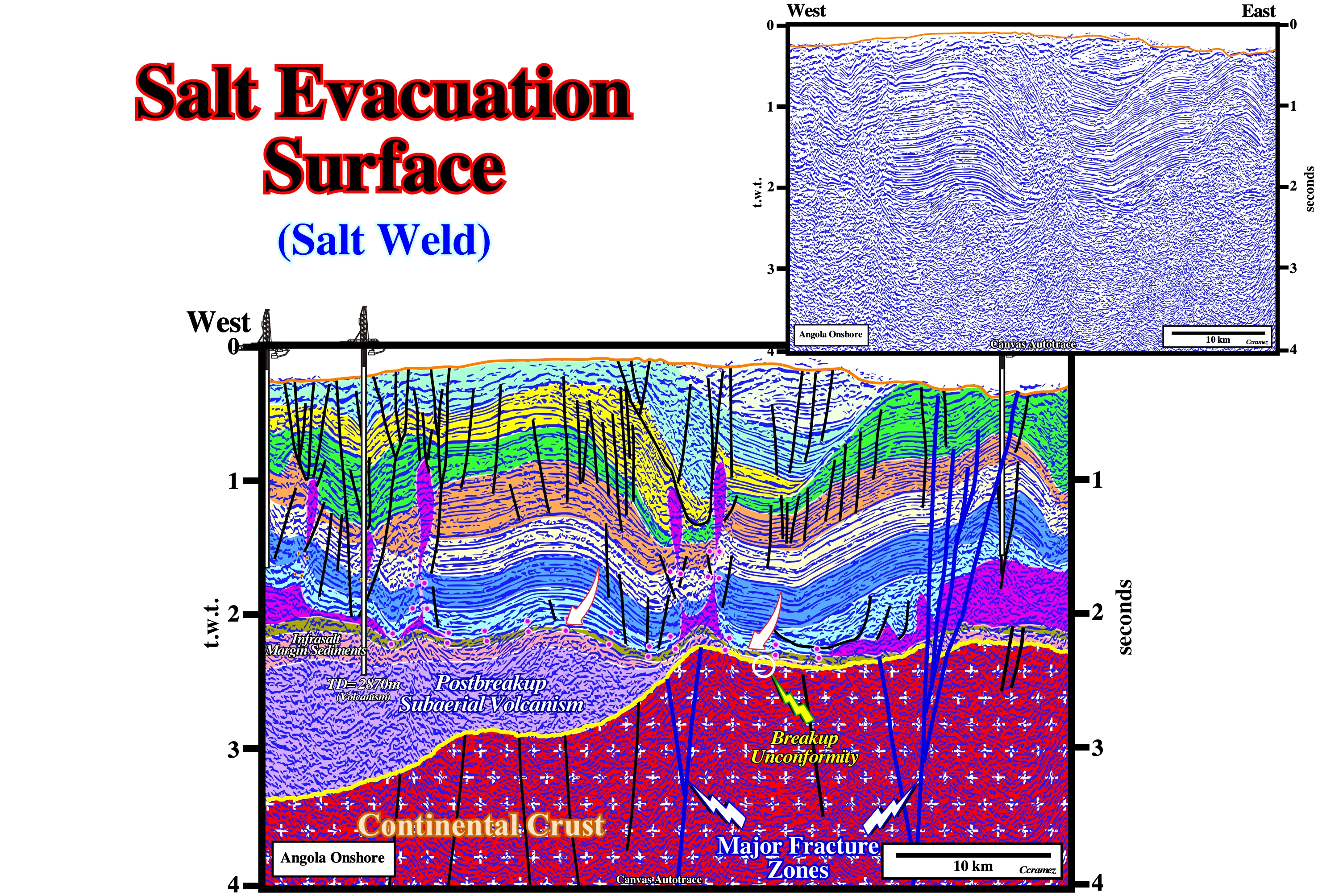
A salt evacuation surface correspond to a primary salt weld. Secondary and tertiary salt welds are, rarely, referred as salt evacuation surfaces. On this tentative interpretation of a Canvas autotrace of an Angola onshore seismic line, the salt evacuation surface is, easily, recognized. It corresponds to the bottom of the salt layer or/and associated salt welds, i.e., it underlines the salt induced tectonic disharmony. The major salt evacuation surface (salt induced tectonic disharmony) separates overburden, deformed by halokinesis, from the undeformed subsalt strata. On this tentative interpretation, westward of the major fracture zones, the subsalt strata is by postbreakup subaerial volcanism (SDRs) covered by a depocenter of lacustrine shales, which can be considered as potential source-rocks.
Salt Expulsion Basin
Synkinematic basin subsiding into relatively thick allochthonous or autochthonous salt. Salt expulsion basins may be the expression of spoke circular or may reflect merely random patterns of differential loading. Some intrasalt basins form up-dip of large salt tongues, which act as barriers to down-slope sedimentary transport.
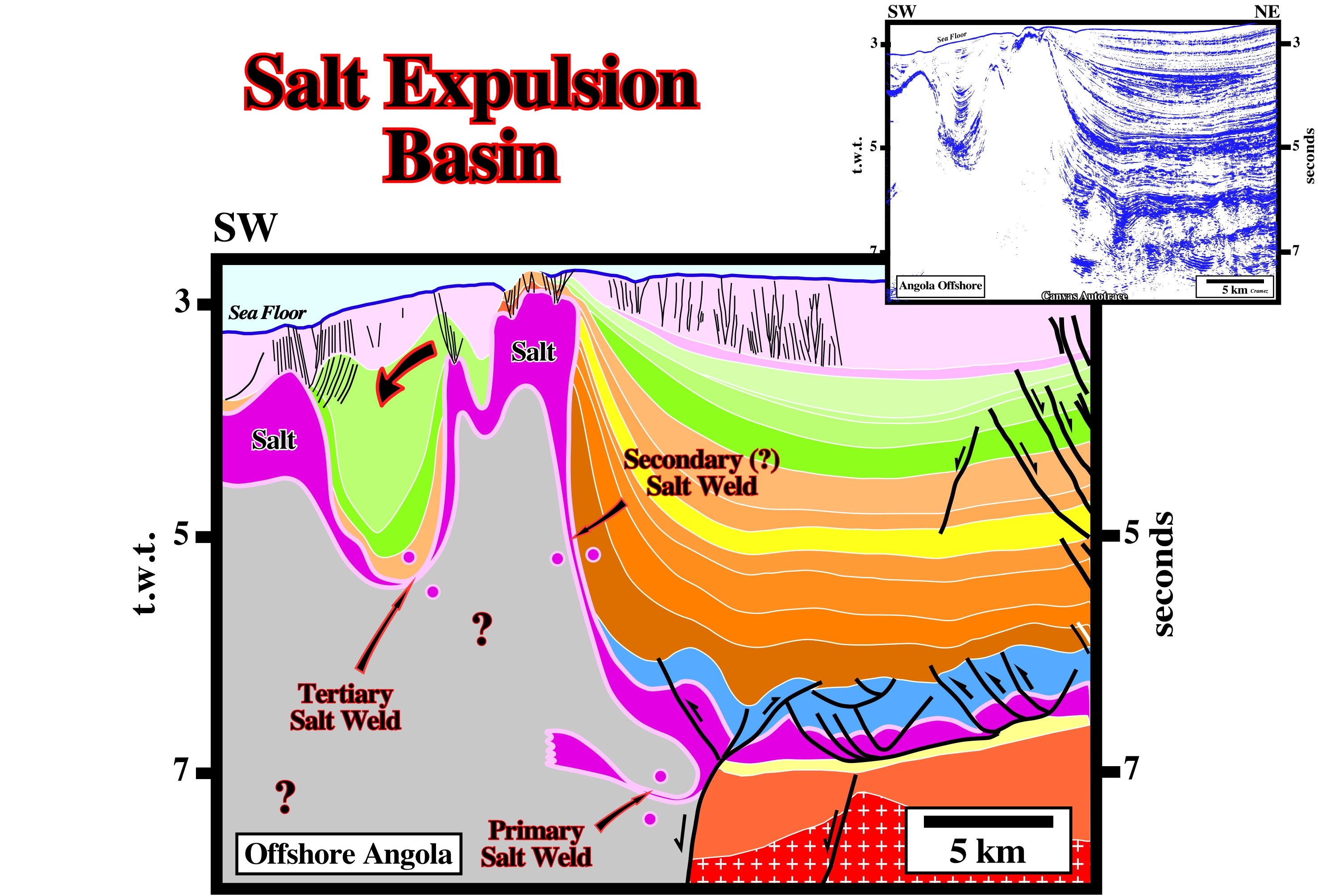
On this line, it is obvious that the mini-basin above the allochthonous salt sheet, can only be explained by a local evacuation of the allochthonous salt. The ramp (or counter-regional fault) along which the autochthonous salt migrated upward is recognized in the central part of the line. Subsalt strata and particularly two rift-type basins are recognized in the lower right corner.
Salt Extrusion
General term used to express outcropping salt structures (in surface or bottom of sea). Salt extrusions can be due to erosion or piercement (with or without compression).
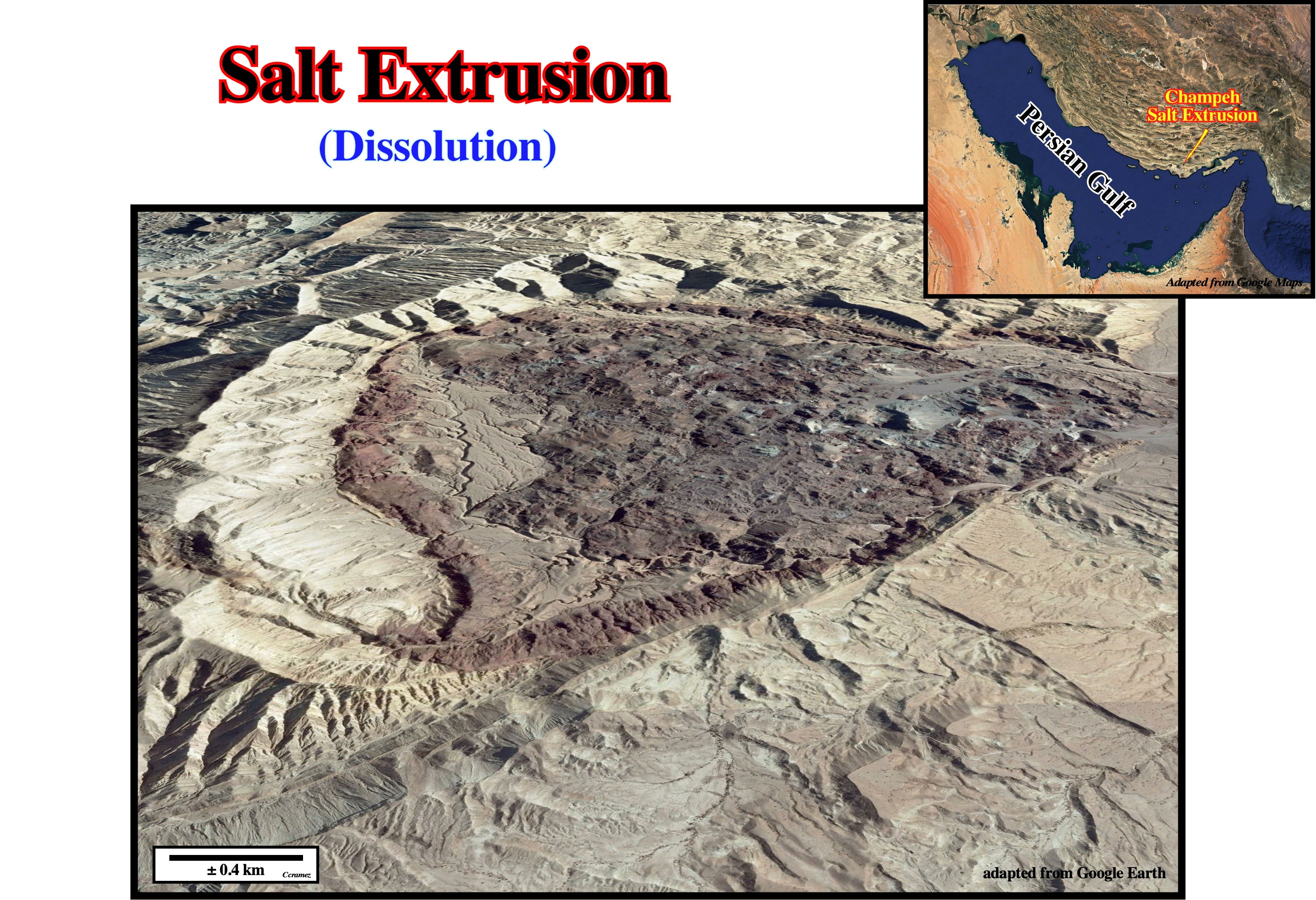
On this Google Earth picture a salt extrusion in South Iran is more than evident, as well as, the associated salt dissolution. Such a salt extrusion is, mainly, due to piercement. A small compression can be associated.
Salt Feeder
See: Counter-regional system.
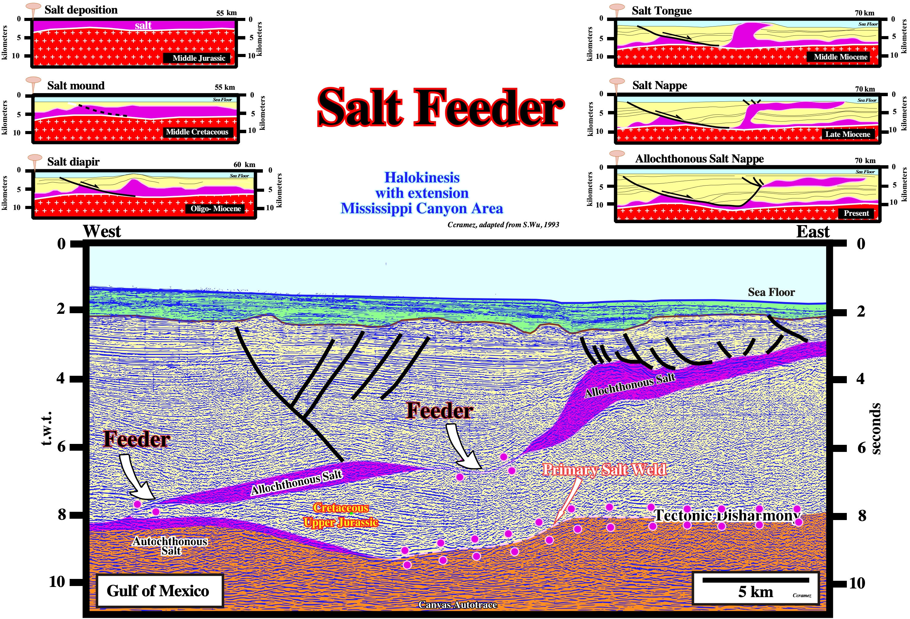
As illustrated on this tentative interpretation of a Canvas autotrace of a GOM seismic a salt feeder between the autochthonous and the allochthonous salt (secondary salt weld) is not necessary associated with a counter regional system. The same is true for a feeder between two allochthonous salt bodies (tertiary salt weld). A primary salt weld is well recognized eastward of the autochthonous. It emphasize the salt induced tectonic disharmony between the subsalt strata and the overburden.
Salt Flat
A steeply inclined and gently inclined segments, respectively, of the stair-step basal contact of a salt tongue. Can be a synonym of salt ramp. Salt flats cut up stratigraphic section in the direction of emplacement. They dip in a direction opposite to the spreading direction of a tongue during the stratigraphic time represented by strata truncated in the basal cutoff adjoining the salt ramp. Ramps form where the ration of aggradation to salt spreading is high. Conversely, flats form where this ratio is low.
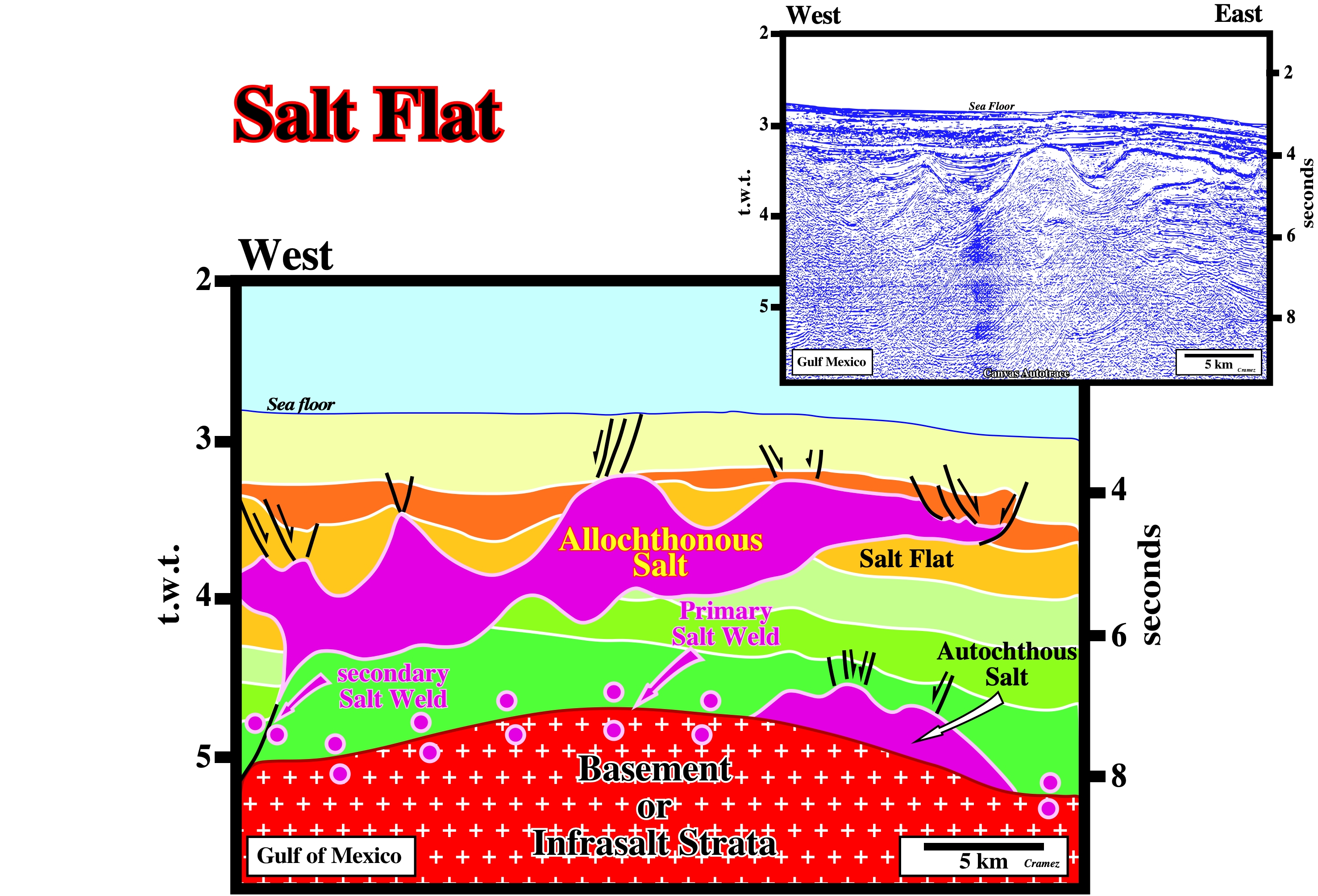
In spite of the stretched horizontal scale, the salt flats, at the bottom of the allochthonous salt sheet, are, quite well recognized, on this tentative interpretation of a Canvas autotrace of a GOM seismic line. The leading edge, i.e. the foremost edge of a spreading salt body, as well as the three small mini-basins developed above the allochthonous salt due to the salt flowage.
Salt Flowage
Lateral or vertical displacement of a salt layer either by differential loading, density inversion or gravity.
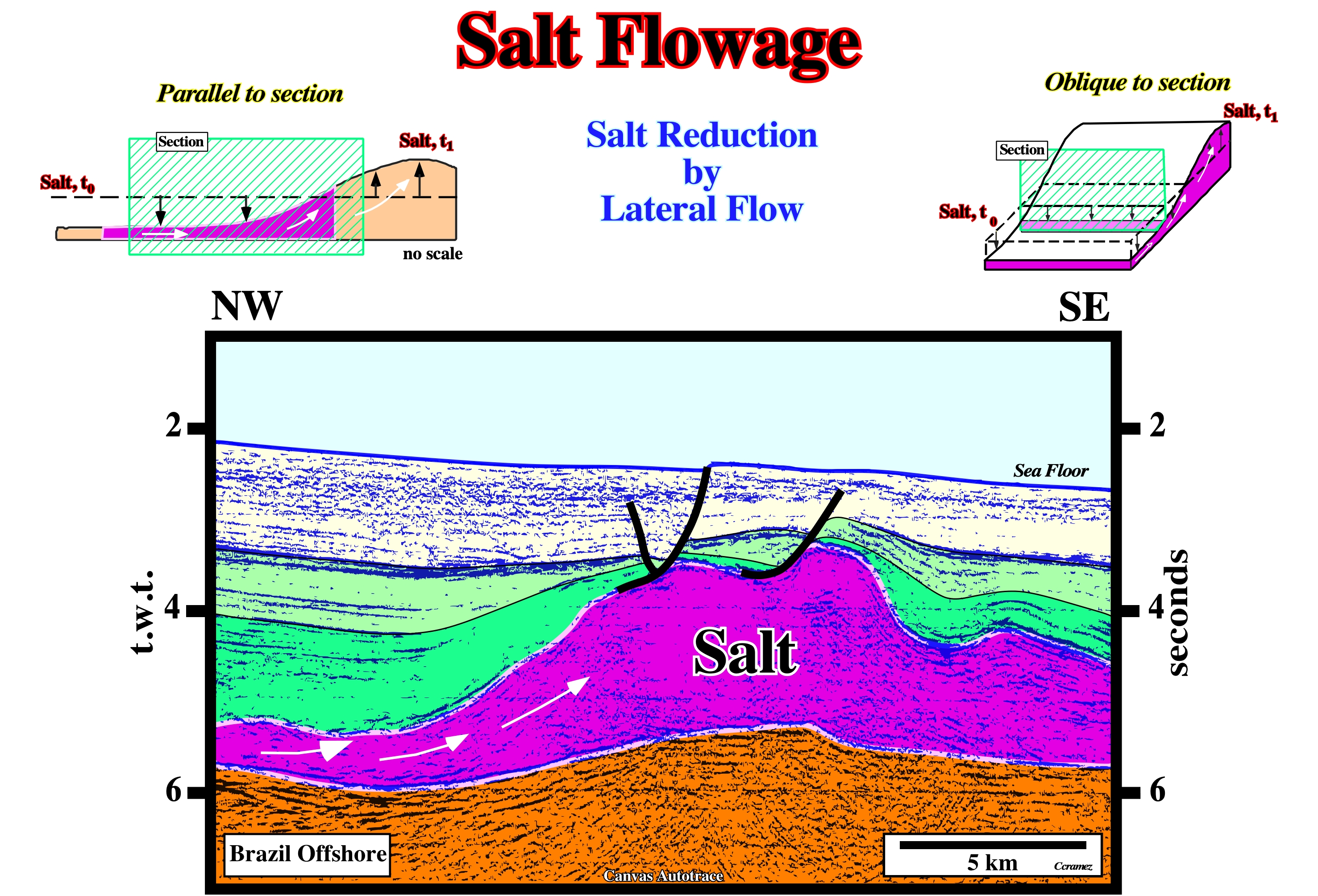
When interpreting seismic lines or autotraces in geological terms, interpreters must know not only the the location (geological setting) but the orientation of the seismic lines in relation to the salt structures, for instance. As illustrated on the above geological sketches, salt flowage is, easily, recognized on seismic lines or autotraces parallel to the salt movement. Contrariwise, seismic lines or autotraces perpendicular to the direction of salt flowage are, often, irrelevant. On this Canvas autotrace of a Brazil offshore seismic line, the orientation of the original seismic line is, more or less, parallel to direction of salt flowage. In fact, it is quite easy to recognize that the salt flowed from NW to SE, i.e., toward the salt mound. Such a flowage created a compensatory subsidence, which is highlighted by the sedimentary depocenter located on the left side of the tentative geological interpretation.
Salt Fold
Synonym of Salt anticline.
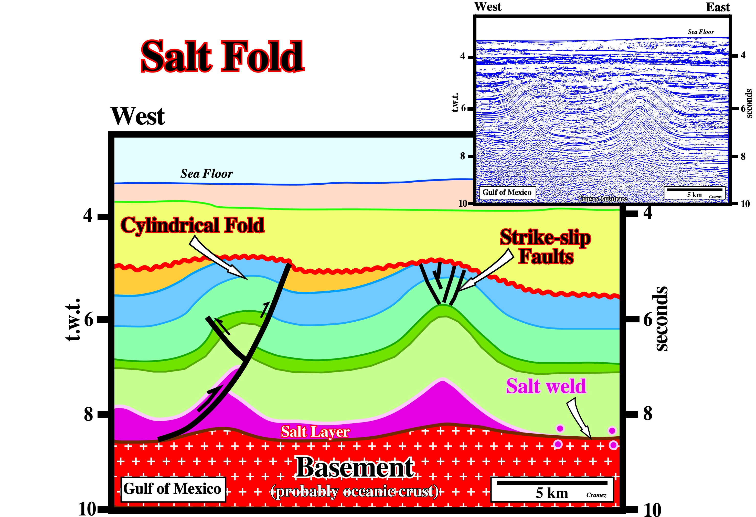
The regional geological setting of this tentative interpretation line, strongly, suggests the salt structures were created by a compressional tectonic regime. The mapping of the faults on the top of the overburden structures shows that they are small strike-slip faults which elongate the axis of the anticline along the σ2. These strike slip faults faults, which were recognized since long-time the in Swiss Jura folds by C.E. Wegmann, are quite frequent in Zabros anticlines. The picked unconformity (in red) called, often, angular unconformity is, in fact an eustatic unconformity (induced by a relative sea level fall) enhanced by tectonics. Tectonic movements cannot alone develop erosional surfaces. A relative sea level fall is required to create an erosional surface. Laterally, this tectonically enhanced unconformity becomes a cryptic unconformity.
Salt Fountain (Bailey, E. B., 1931)
This expression comes from a metaphor used by Bailey: "salt diapirs are slow-motion fountains".
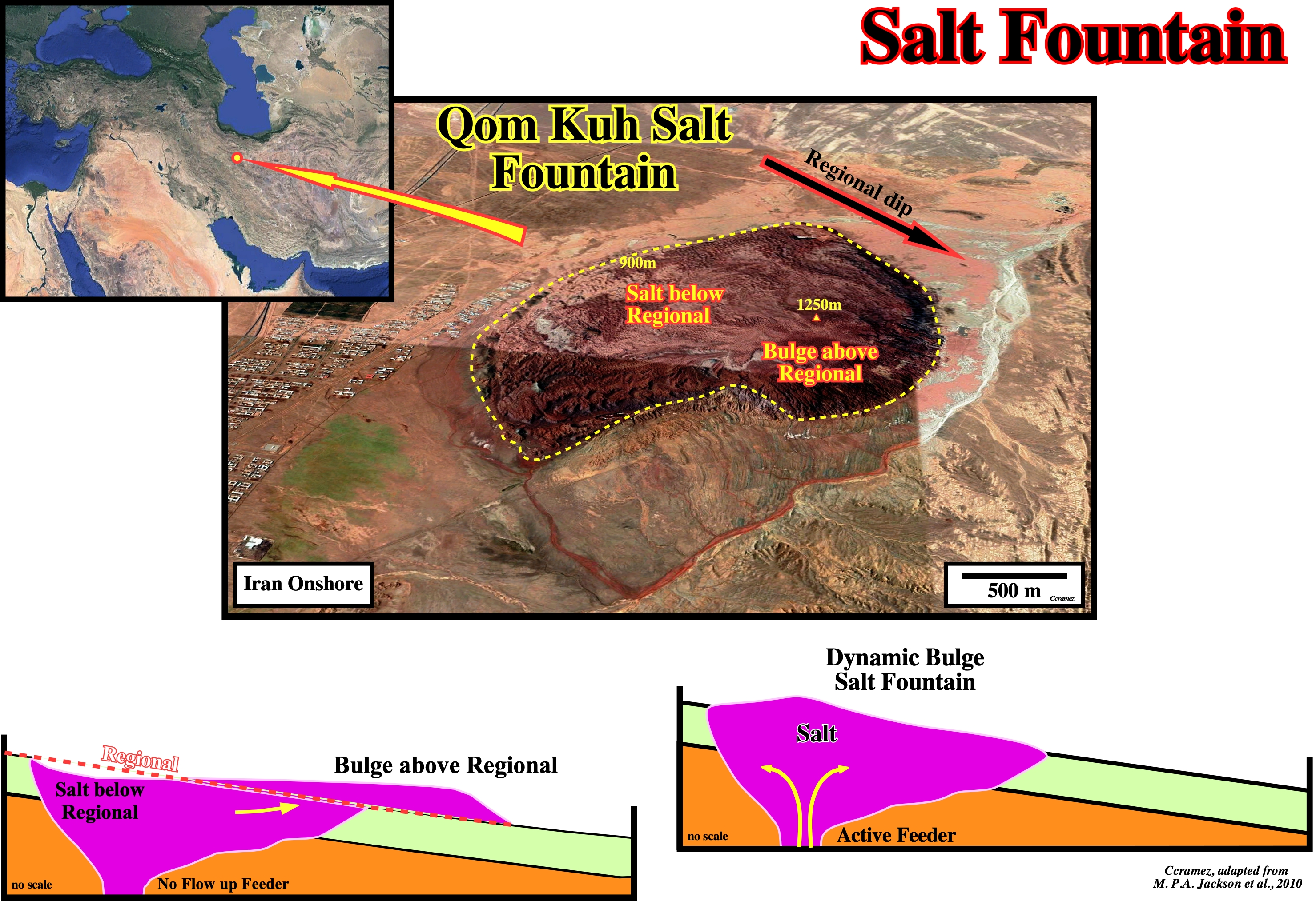
As illustrated on these geological sketch, when a salt diapir arrives near the surface it, normally, takes a flaring geometry, since the flow rate of the salt minus dissolution divided by the aggradation rate minus compaction becomes between 100> R°/A°>10 or, in other words, since the pressure of the salt against the adjacent rocks is not compensated by the pressure of the sediments against the salt. At shallow depth, the density of the salt is higher than the density of the sediments, what is not the case in higher depth, once the salt is not compacted in depth, it keeps, more or less, the same density. Arriving in surface, if the feeder becomes inactive, the salt can flow downdip, when the morphological conditions are favorable creating a downdip salt bulge above the regional topographical dip, while above the feeder the salt is below the regional dip. The Qom Kuh diapir seems correspond to a typical salt fountain : the feeder seems to be inactive with a significant bulge (1,250 meters) above regional topographic dip.
Salt Glacier
Sheetlike extrusion of salt issuing from an exposed diapir and spreading beneath air or water. Synonym of Namakier.
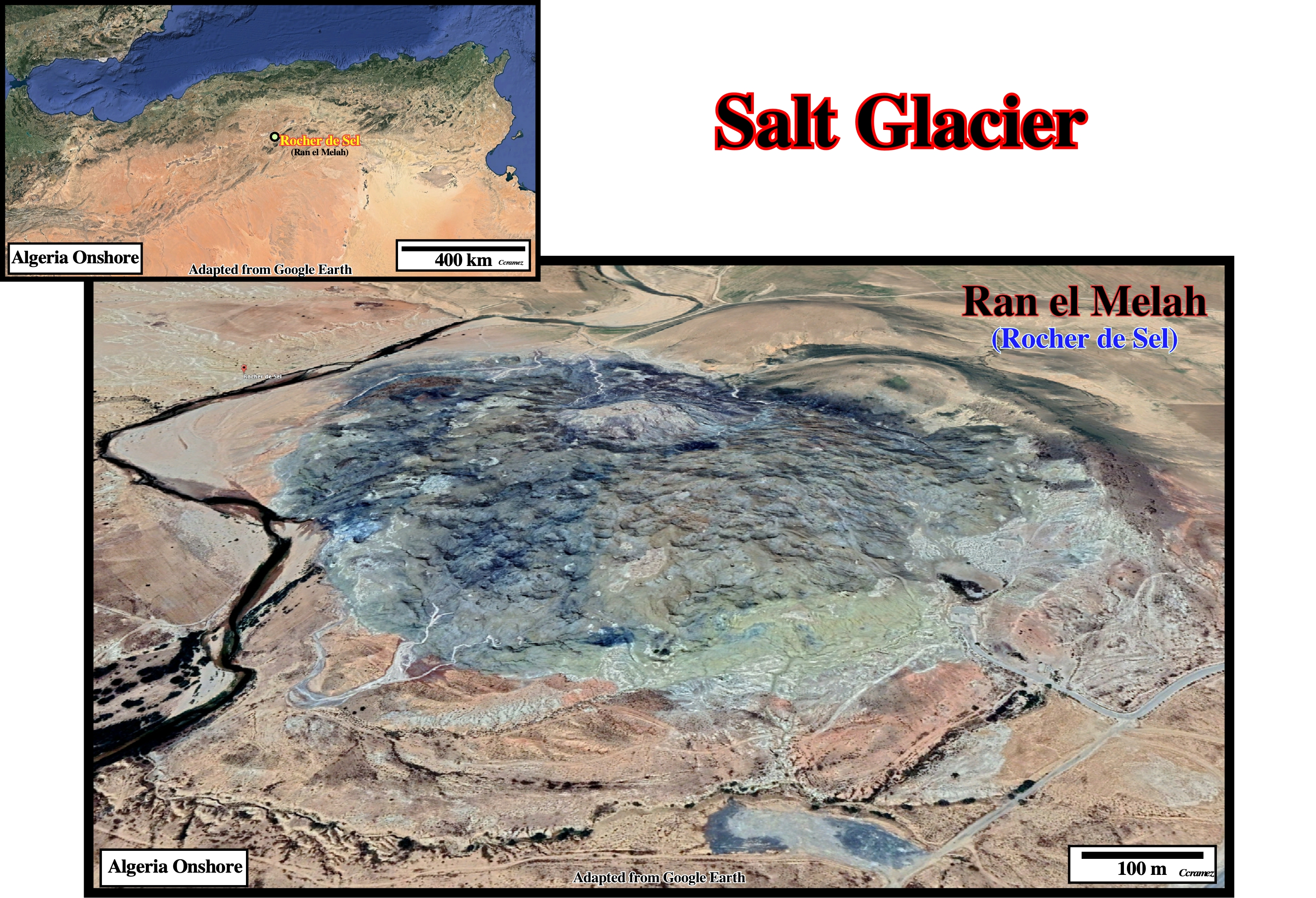
The "Rocher de Sel" in Algeria onshore seems to be a typical salt glacier, once the salt seems spreading in surface, as it is the case in the Jabal Al Milh glacier illustrated in the figure below.
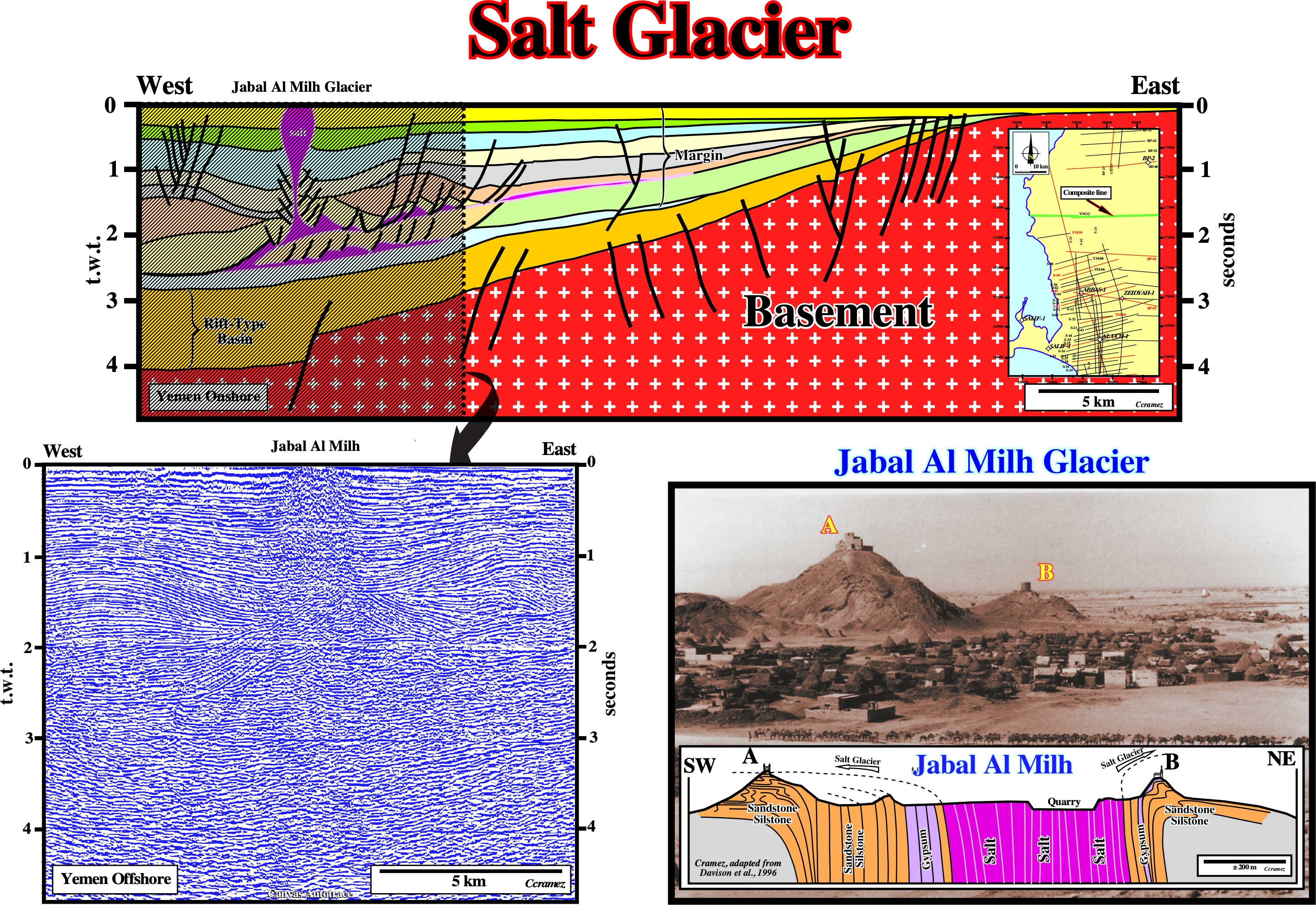
The regional tentative geological interpretation of a Canvas autotrace of a composite cross section of Yemen onshore illustrates the a large rift-type basin (predating the breakup of the lithosphere), which is covered by a divergent margin (postdating the breakup unconformity). In the divergent margin two salt level are recognized. The lower level is the autochthonous salt, whose pinchout is underline by a normal fault. The upper salt level is allochthonous from which the Jabal Al Milh diapir rose until surface. The geological cross section of the Jabal Al Milh proposed by Davison et al. (1996) illustrated above clear indicates the salt bulges (A and B), above the regional topographical dip, induced by outward salt spreading.
Salt Laccolith
Intrusive salt sheet whose ratio of maximum width to maximum thickness is between 5 and 20. Its upper part is typically concordant, whereas its lower contact is commonly slightly discordant.
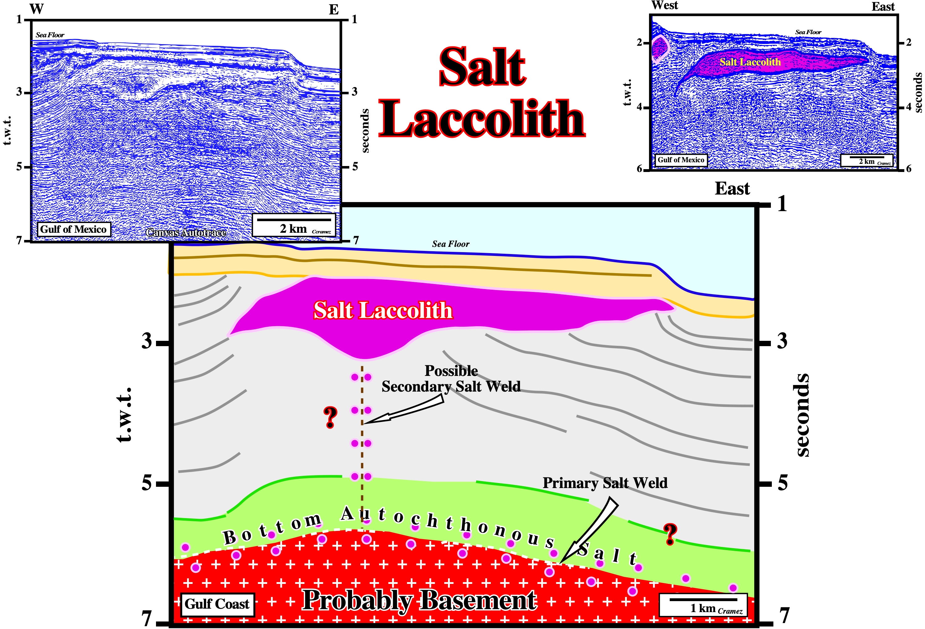
On this preliminary tentative interpretation of a Canvas autotrace of a GOM seismic line, a deep primary salt weld (around 6 seconds) underlines the evacuation of autochthonous salt. In the upper stratigraphic levels, allochthonous salt is quite obvious. Taking into account the dimensions of the central salt body, as well as, the geometry of the upper and lower contacts, it can be considered as a salt laccolith.
Salt Lateral Flow
Lateral displacement of the salt inducing a compensatory subsidence.
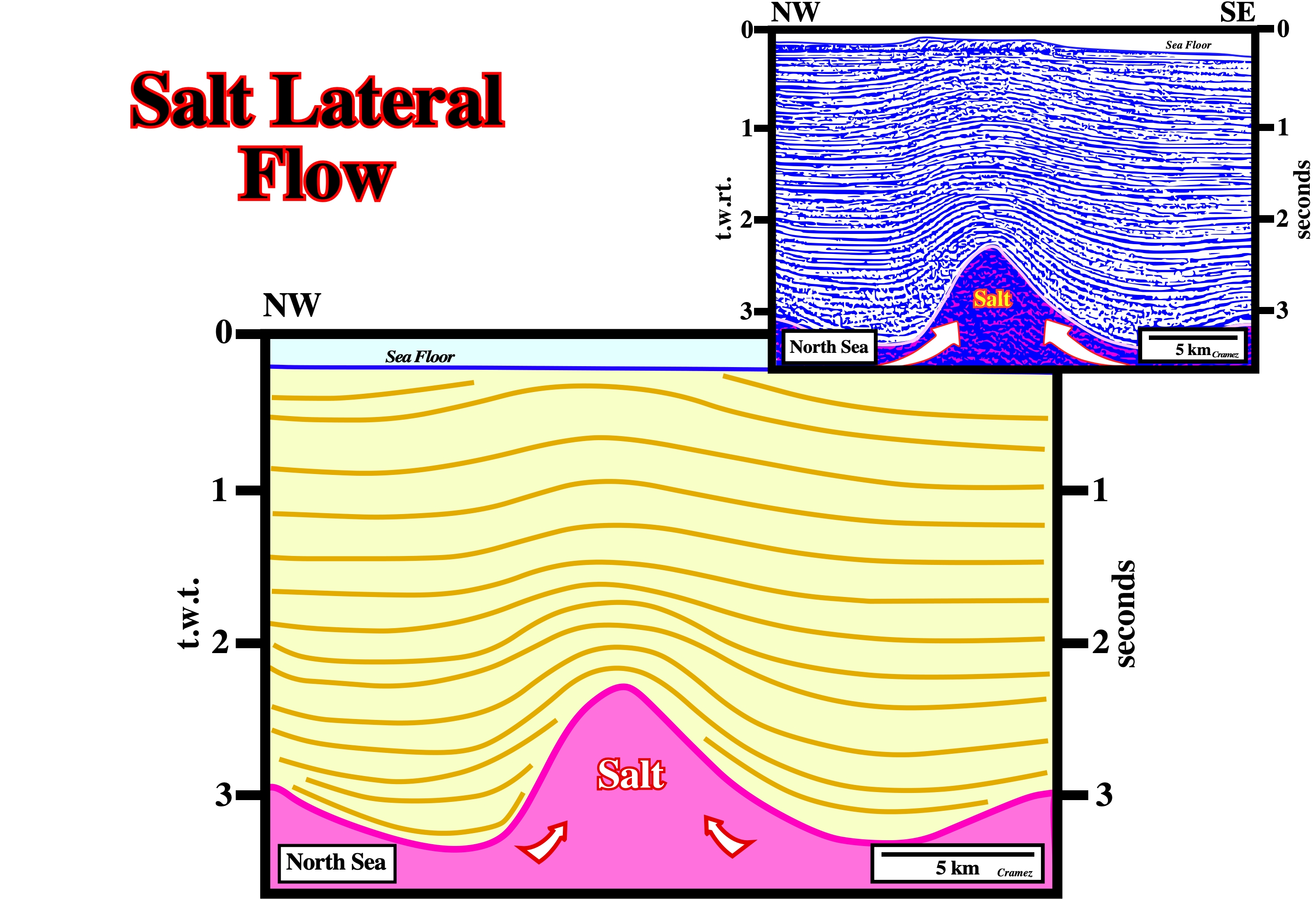
As illustrated on this seismic line, the lateral flowage of the salt is the main responsible for the creation of space available for the sediments, that is to say, it induces a compensatory subsidence. In fact, in the lower intervals of the overburden, the thickness variations (thin above the bulb and thick above the salt synforms) can only be explain by salt flowage, in spite of the fact, that the geometry of the upper intervals of the overburden suggests a late shortening.
Salt Layer
Synonym of salt. A salt layer can be an autochthonous or allochthonous.
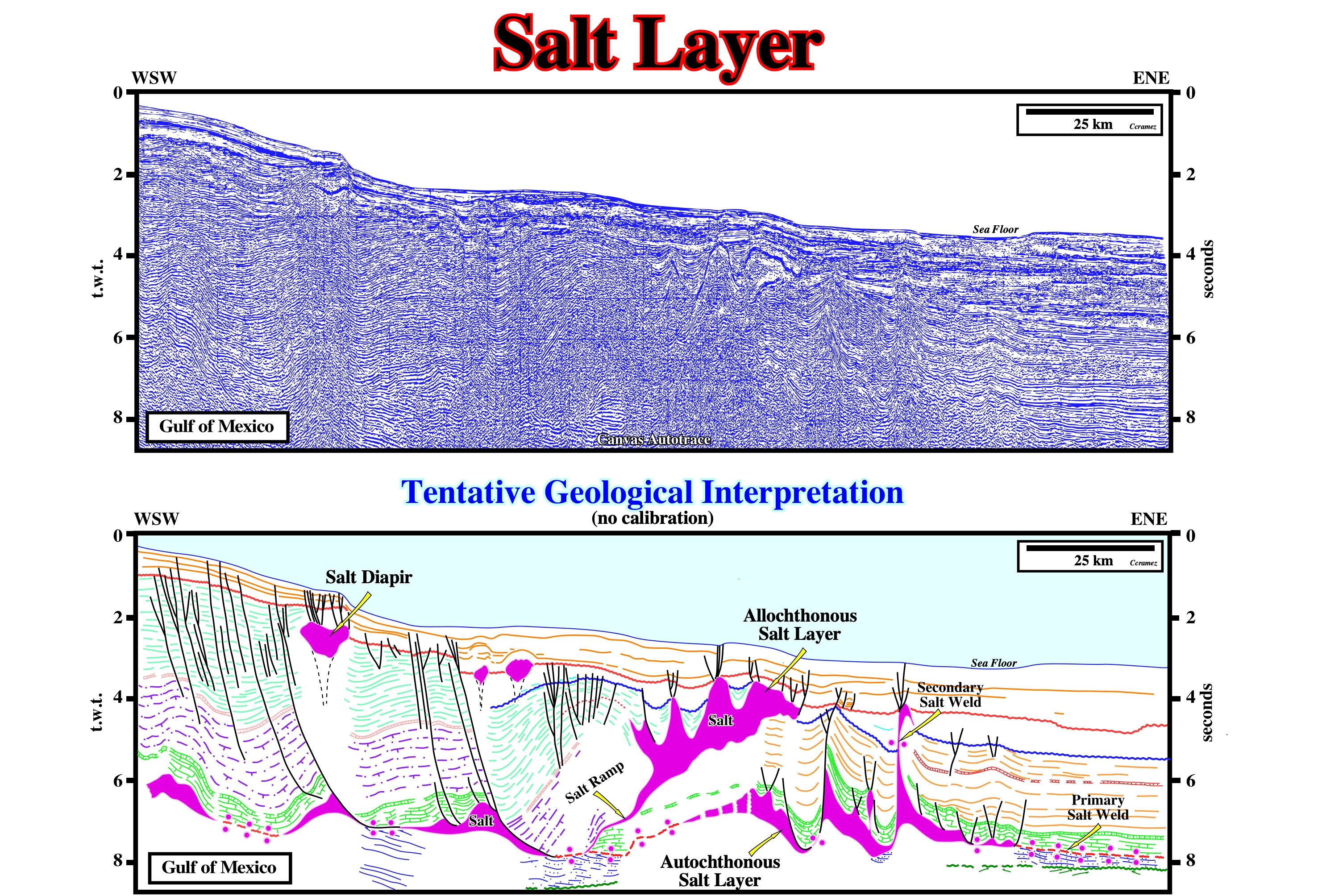
On this tentative geological interpretation it is easy to see that in Gulf o Mexico the salt can be found in different salt layers. The lower one is autochthonous, i.e., the salt layer is in its original stratigraphic position and the associated salt domes are first generation diapir. The autochthonous salt layer can disappear laterally by salt flowage and be replaced by a primary salt weld. The upper salt layer is allochthonous, i.e., it is not in its original stratigraphic position. The allochthonous salt layers is connected with the allochthonous salt either by a secondary salt weld (seismically speaking there is not salt associated, but the seismic resolution must be taken into account) which in particular case can be, more or less, vertical, either by a salt ramp or feeder when the salt is, seismically, visible. Both cases are recognized on this tentative interpretation. The salt diapirs rooted in the allochthonous salt are considered to be second generation diapirs. Similarly, the salt welds recognized on the allochthonous salt layer are considered as tertiary salt welds. Quite often, mini-basins (or salt expulsion basins), i.e., synkinematic depocenters are induced by a compensatory subsidence of thick allochthonous salt. Many geoscientist reserve the term mini-basin, exclusively, for depocenters associated with autochthonous salt.
Salt Molding
Syndiapiric deposition of stiff overburden around salt diapir. Since 1933, Barton introduced the concept of downbuilding to account for salt structures that pierce clastic sediments. See: Molding Models.
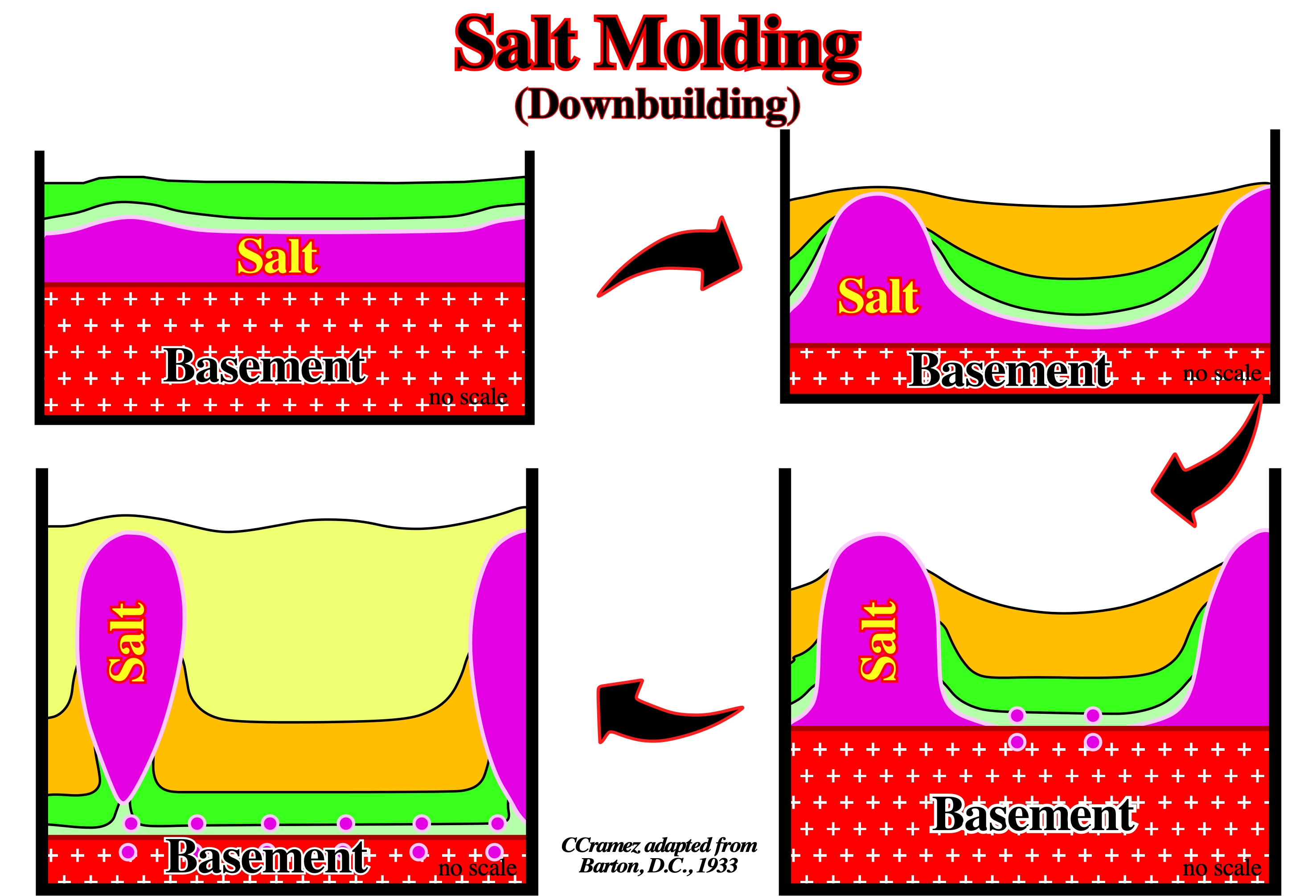
In this particular example, instead of a buried autochthonous salt layer upthrusting, actively, toward the surface through an overburden already in place, Barton (1933) argued that cores of initially tabular salt layers remained passive but emergent near the sea floor while the top of the surrounding salt was buried ever deeper by clastic sediments. The internal configuration of the interdomal structures can, often, suggest, what is the predominant mechanism, particularly, when the differentiation between synkinematic and postkinematic can be done.
Salt Mound
Synonym of salt pillow, that is to say, a more or circular or sligthly elongated up-welling or intumescence of salt, roughly, concordant with the overburden. This term is, generally, referrred the salt monticles in the first the steps of halokinesis.
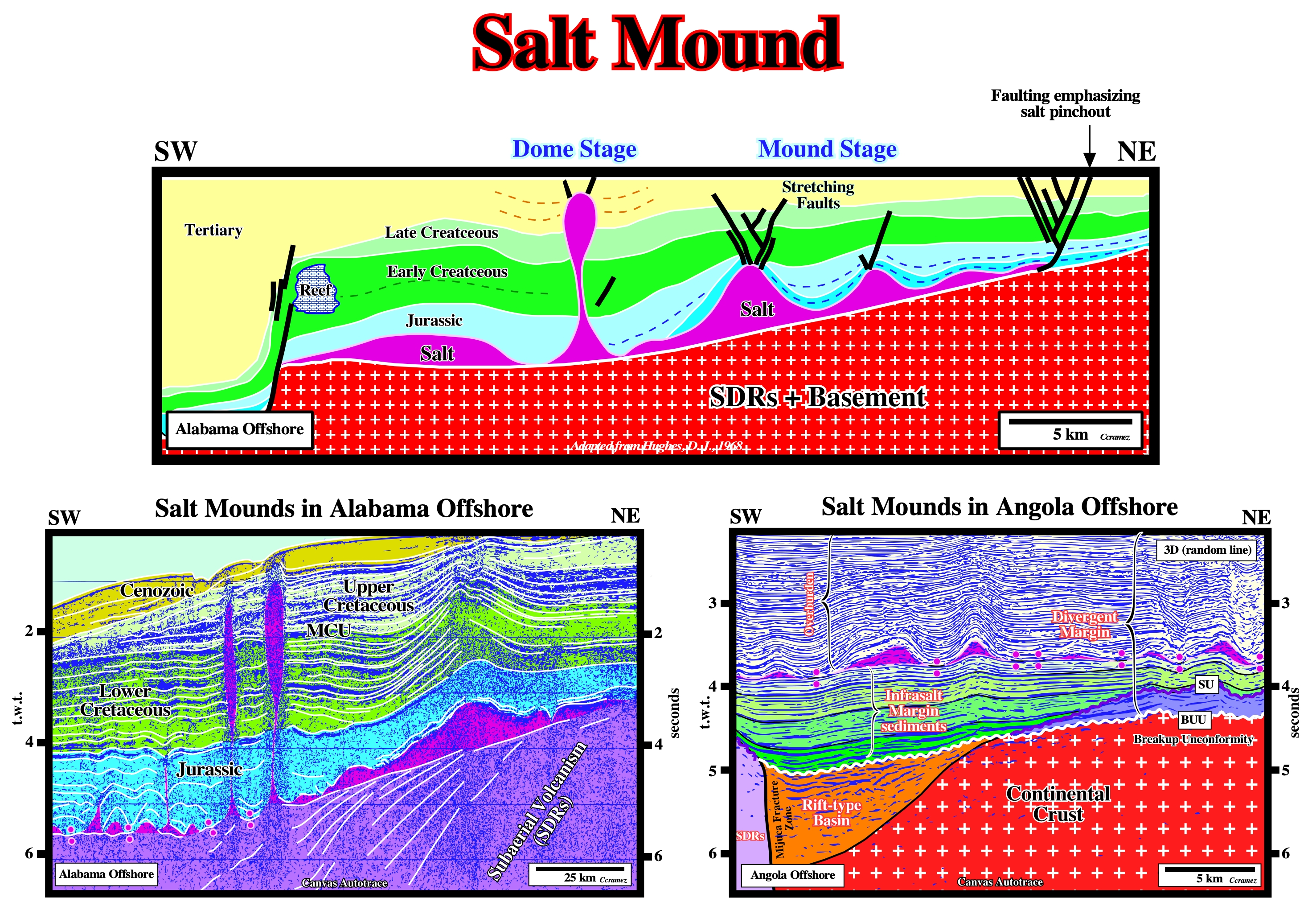
Salt mounds can be formed anywhere where there is a compensatory subsidence, as for instance in association with the formation of a turtle back structure, however it is rather used to describe salt monticules in the first steps of halokinesis. Three stages of diapirism are, often, considered : a) Mound Stage ; b) Dome Stage and c) Post-Dome Stage as illustrated on the above Alabama offshore geological cross section. The first two stages i.e., the mound and stages, are well illustrated near the margin of the salt basins (GOM, Alabama offshore, Angola offshore, Mediterranean Sea, etc.). The post-dome stage is easily documented by the salt structures found mainly in the deep water of the salt basins. In the mound stage, the compensatory subsidence induced by salt flowage creates two depocenters each side of a residual salt high (mound or salt pillow), in which the stratigraphic intervals thicker toward the higher compensatory subsidence. Above the salt mound the subsidence is smaller and so the stratigraphic intervals are thinner.
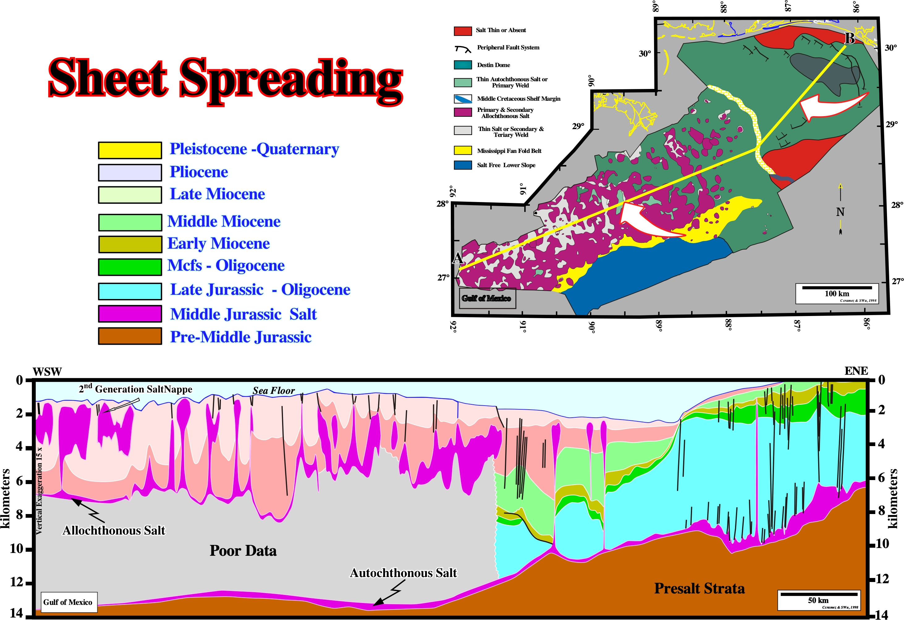
Salt Nappe
Salt tongue whose lower contact is a thrust fault, shear zone, or zone of inverted strata.
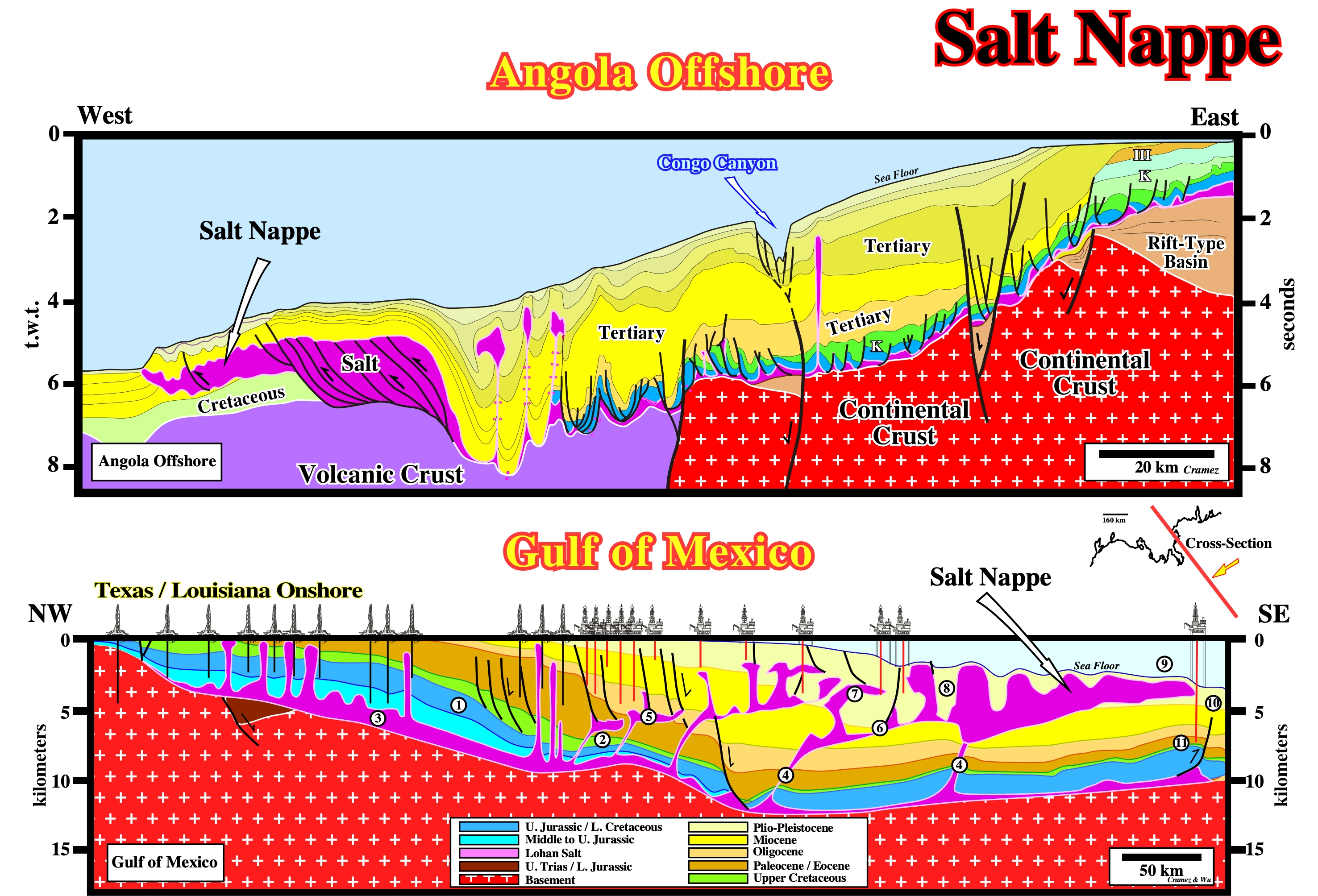
On the tentative geological interpretation of a Canvas autotrace of an Angola offshore composite seismic line, it is interesting to notice the salt distal thrust fault corresponds to the seaward limit of a salt basin (this is particularly evident in a depth conversion version). Seaward, the salt is allochthonous and forms a salt nappe, which has been slightly reactivated and shortened, probably, by ridge push forces. It is quite obvious the thickness of the salt is apparent and due to thrusting. Some argued the salt being thicker in the ultra deep offshore was the proof of an unique pristine salt basin that was, later, split in two. Recently, such a hypothesis has been systematically falsified. On the GOM tentative interpretation, different salt nappes were formed as the terrigeneous supply progradate seaward. The major seems to be the Sigsbee salt nappe. Several generations of diapirs are easily recognized. On this tentative interpretation the numbers represent: (1) The limit “platform / slope” at the Middle Cretaceous ; (2) The sedimentary interval with generating hydrocarbon potential, which, roughly, corresponds to the peak transgression of the post-Pangea continental encroachment stratigraphic cycle (Cenomanian-Turonian ; (3) The autochthonous salt ; (4) The salt ramps, between the autochthonous and the allochthonous salt layer ; (5) The 1st generation of allochthonous salt ; (6) Salt and fault welds associated with the allochthonous salt ; (7) The 2nd generation of allochthonous salt ; (8) The salt expulsion basins upon salt nappes ; (9) The Sigsbee escarpment ; (10) The Mississippi deep sea fan and (11) The Perdido fold belt.
Salt Pillow
Subcircular upwelling of salt with concordant overburden.
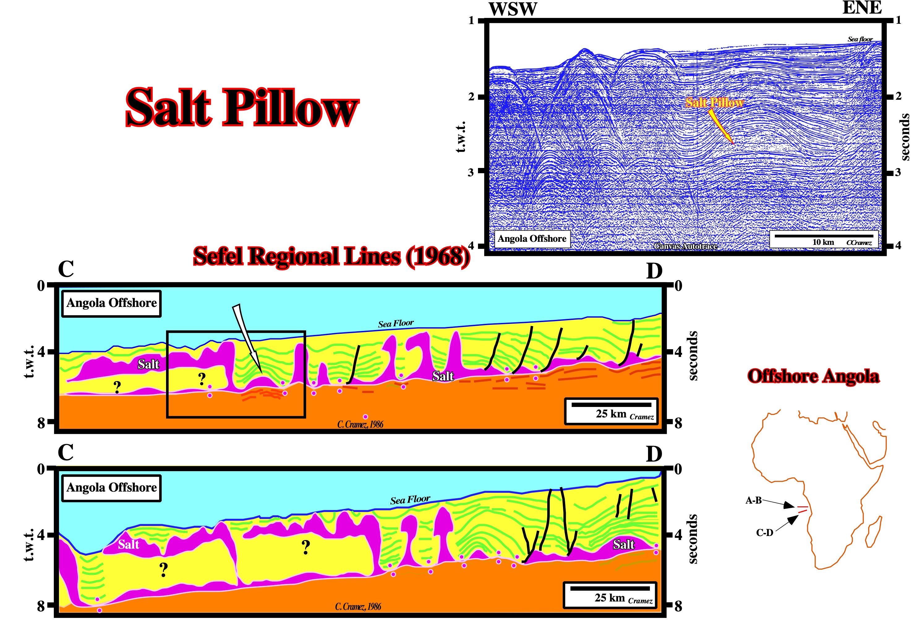
The salt pillow is completely disconnected of the mother source layer. It is limited by two primary salt welds. This antiform salt structure (residual high), recognized in 1968, on Seffel lines, became, recently, well known of all geoscientists working in West Africa offshores. Indeed, major oil pools have been found around the top of the antiform .Notice the slight pull-up of the tectonic disharmony induced by the salt pillow on other hand do not forget that an oil pool is a subsurface oil accumulation. An oil field can consist of one or more oil pools or distinct reservoirs within a single large trap.
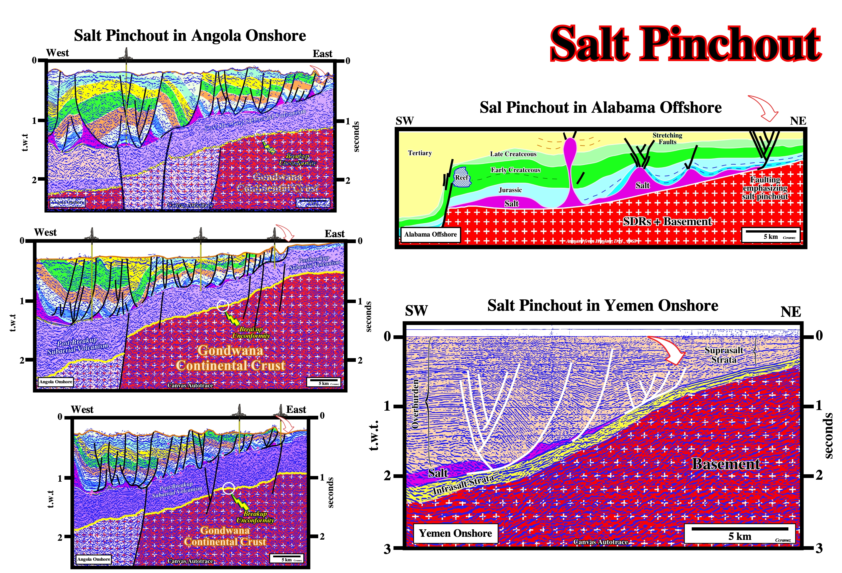
Salt Pinchout
Termination or end of the salt layer or when the salt narrows or thins, progressively, in a given direction until it disappears. The updip limit of a salt basin is almost always characterized by a graben structures in the overburden, as illustrated on the geological map of Gulf Coast.
Most of the salt basins are associated with continental margins. The salt deposition postdate the breakup of the lithosphere and are directly or indirectly associated with the sea floor spreading, as it is the case, for instance, in South Atlantic offshores. In these cases the seaward limit of the salt layers is, often, against the oceanic crust with a stacking of salt thrusts, which gives an higher, but apparent salt thickness very well visible on the seismic lines. The compressional tectonic regime responsible by such a shortening seems to be a counterpart of the predominant extensional tectonic regime in the middle and proximal sectors of the divergent margin. The proximal pinchout of the allochthonous salt layer is, often, difficult to see due to seismic resolution. As illustrated on these tentative geological interpretations of Canvas autotraces, it develops, almost always, in the overburden a typical normal faulting. In the majority of the salt basins that I studied, the proximal pinchout of the salt emphasize the beginning of the lengthening of the overburden (extensional tectonic regime) induced by a gravitative salt flowage.
Salt Plug
Synonym of Salt Stock.
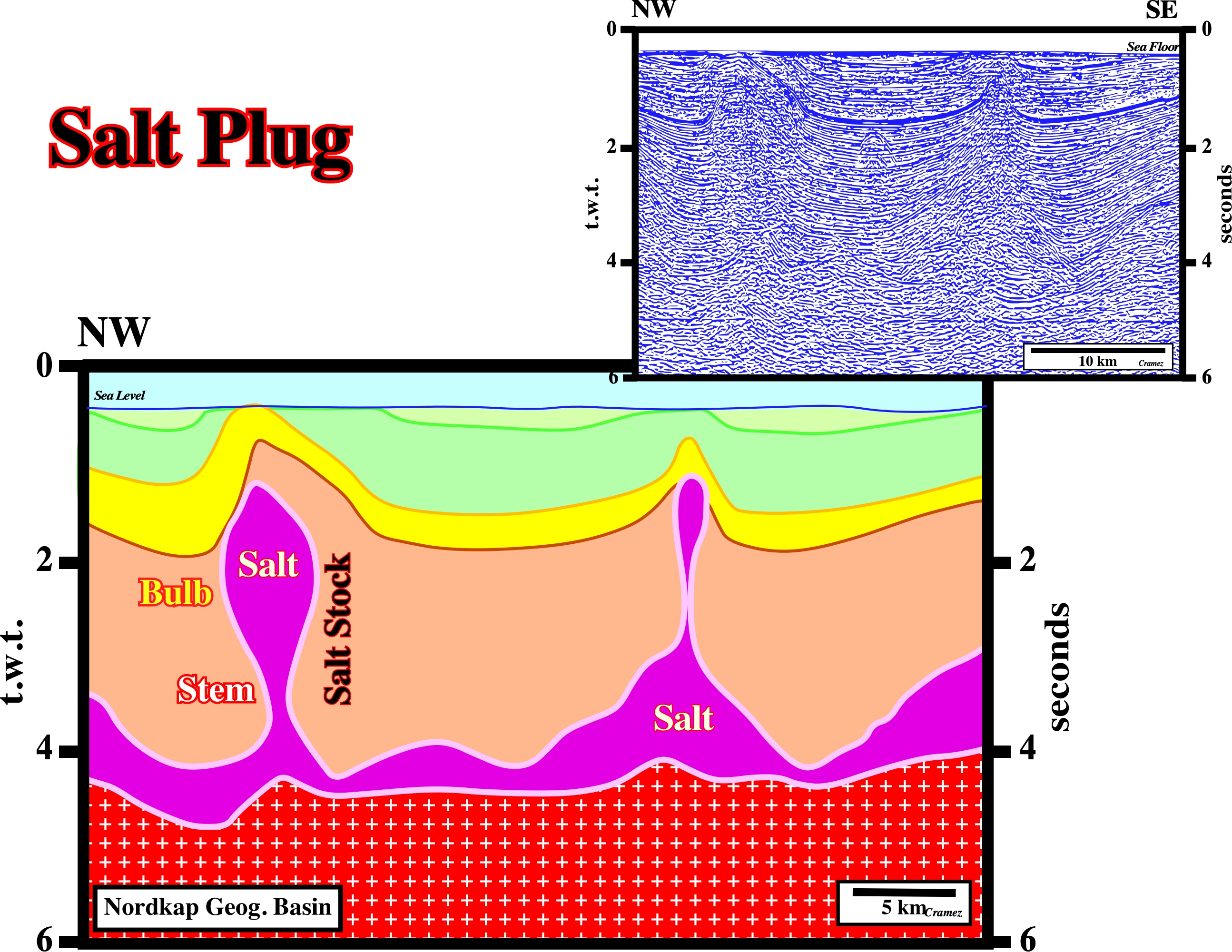
As illustrated above, salt plugs are composed by a stem and a bulb. On this tentative interpretation of a Canvas autotrace of the Nordkapp geographic basin seismic line, the salt stock is disconnected from the mother source layer. Two primary salt welds separate the salt stock from the mother salt layer.
Salt Pod
A small basin, in which the brine starts to deposit salt. It is often assumed that salt basins, as the South Atlantic salt basins are, in fact the agglutination of multitudinous salt pods.
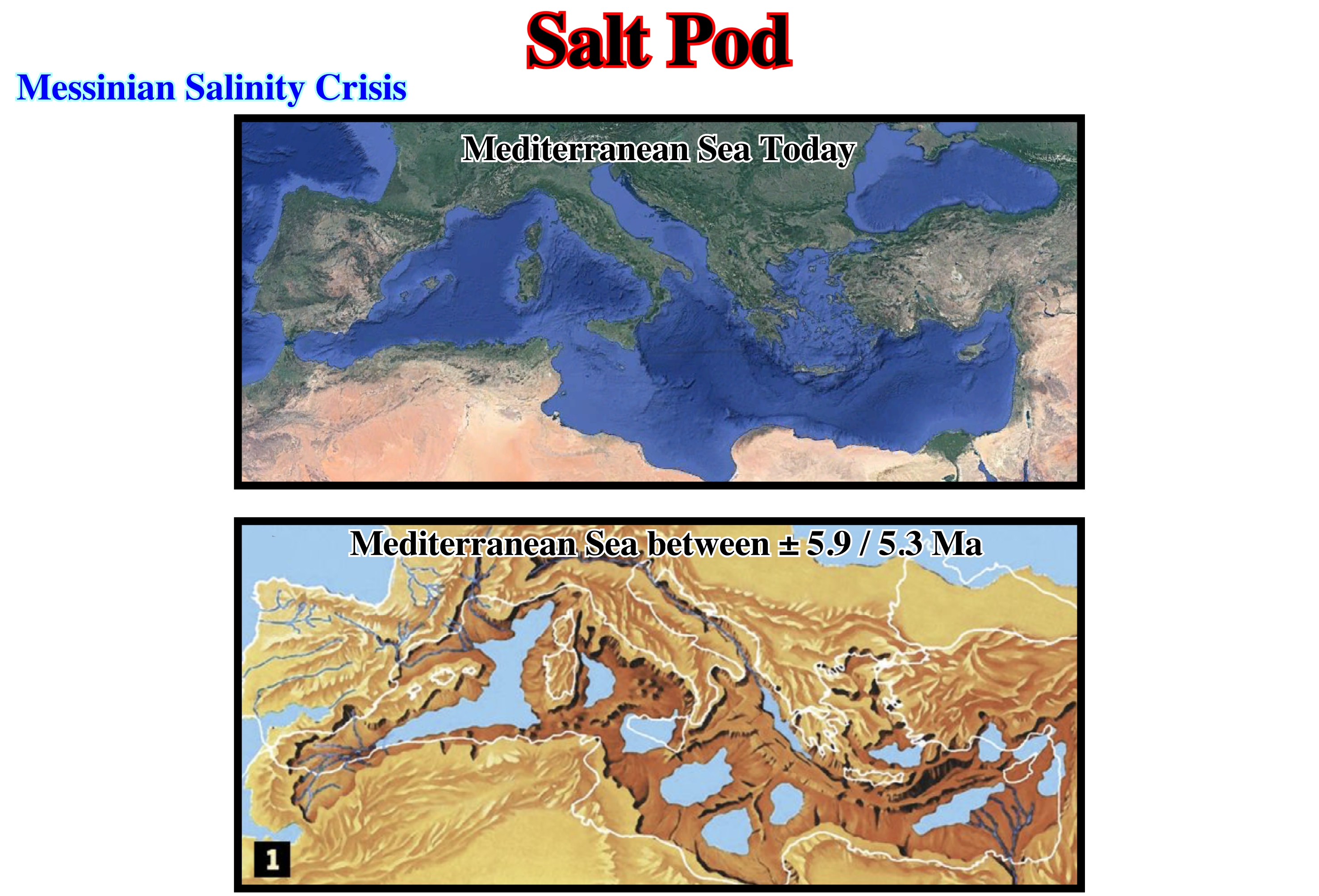
The Messinian drying of the Mediterranean sea seems rather of tectonic origin than a consequence of the Plio-Pleistocene glaciation. It is, probably, due to the gradual closure of the Strait of Gibraltar, as a result of the northward movement of the lithospheric African plate. This closure prevented eustatic rebalancing with the Atlantic Ocean and led, locally, to a drop in sea level (relative) of about 1,500 to 2,500 meters. At the rate of 3,300 km3 / year of net evaporative loss, the Mediterranean basin (3.7 Mkm3) dry up, roughly, in 1,000 years, leaving a salt layer with some tens meters thick (decreasing the average salinity of the the world ocean and rising its freezing point) and rising the absolute sea level around 12 meters (the evaporated water reached the oceans when it fell as rain or snow). The Aral Sea, formerly the world’s fourth largest lake in area, is disappearing. According to Micklin, P. P., (1988), between 1960 and 1987, its level dropped nearly 13 meters and its area decreased by 40 percent. Recession has resulted from reduced inflow caused primarily by withdrawals of water for irrigation.
Salt Ramp
See: Feeder or Counter-regional system.
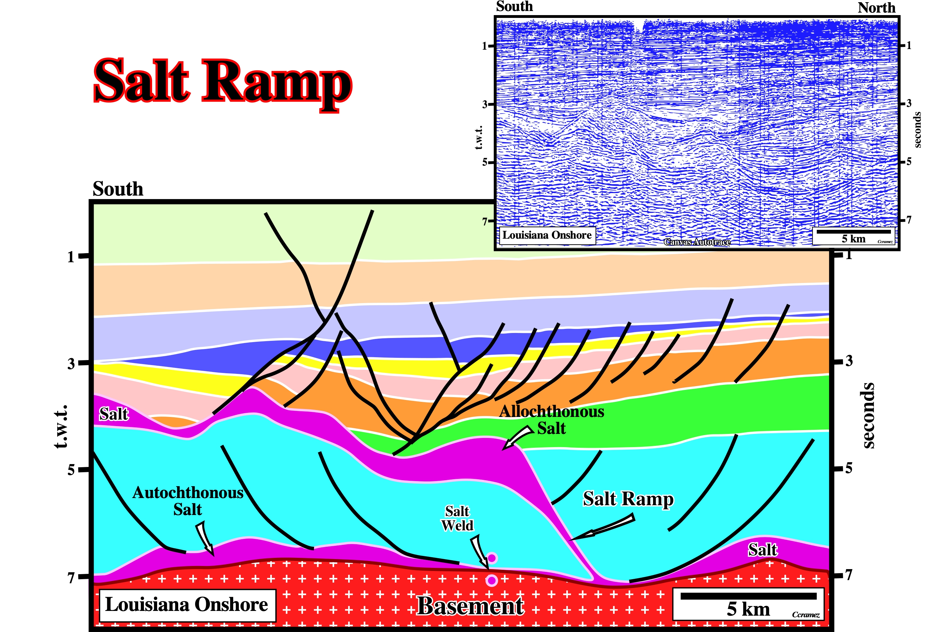
A salt ramp is a feeder of allochthonous salt structures in which the salt thickness is higher than the seismic resolution, i.e., the salt can be recognized on seismic lines. OA salt ramp can be associated with counter-regional fault. A fault, normally, a growth fault induced by salt evacuation, looking continentward (landward vergence), which is not the case on the above tentative geological interpretation.
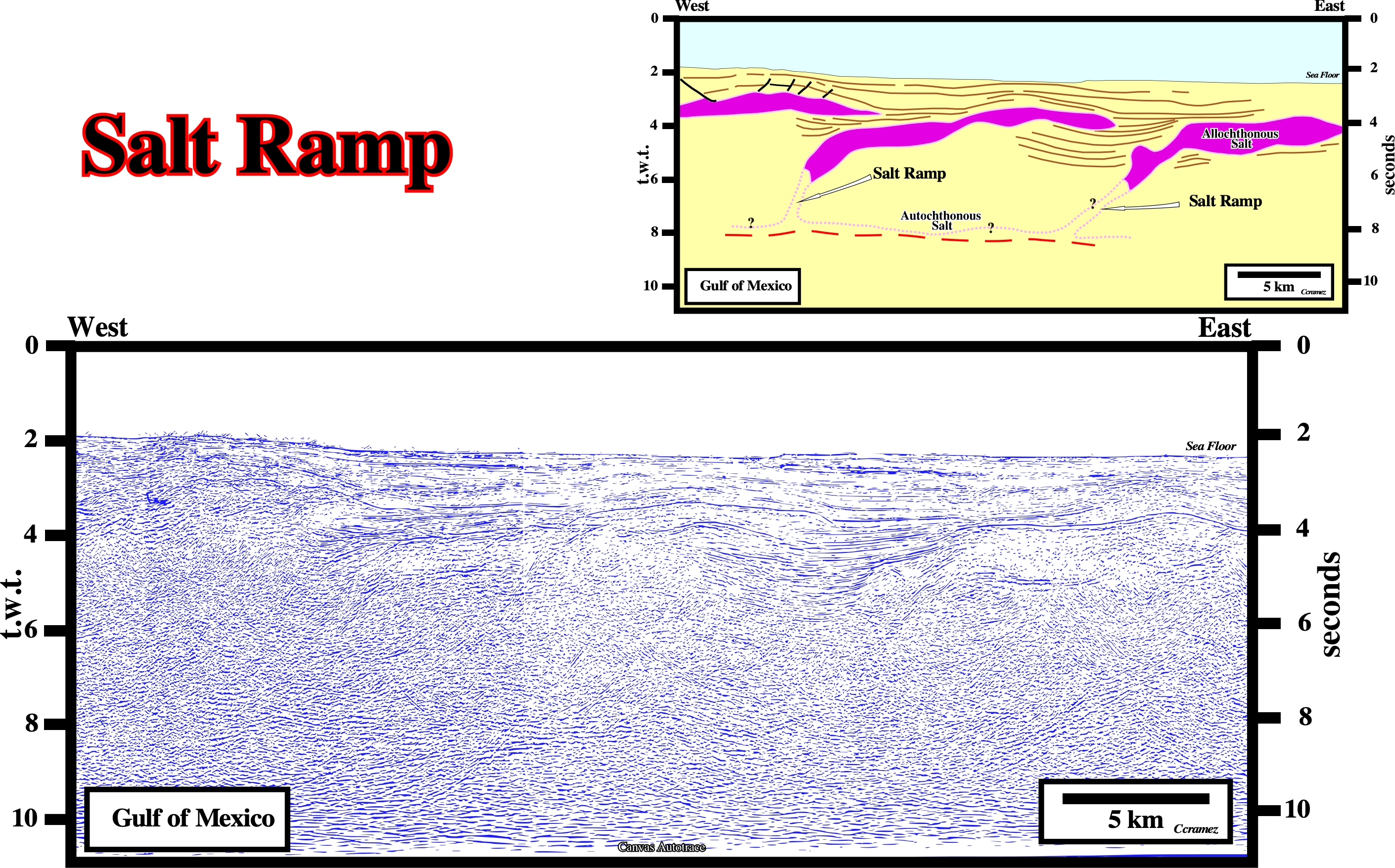
On this Canvas autotrace, as illustrated on the above preliminary tentative interpretation, salt ramps connecting the allochthonous salt nappes with the autochthonous salt are speculative. Such an interpretation is what a geoscientists trained in salt tectonics expects. Said in another way, a geoscientist looking at a seismic line or at an autotrace (manual or made with a drawing software) just see what we knowns or what he expect to see ("Theory precedes Observation, K. Popper, 1934).
Salt Reduction
Mass transfer of salt over time, resulting in an obvious change in area of salt in cross section, by: (1) Volume loss due to dissolution, (2) Isochoric flow out of the plane of section, including smearing along decollement faults, (3) Isochoric flow within the plane of section but beyond the ends of the cross section.
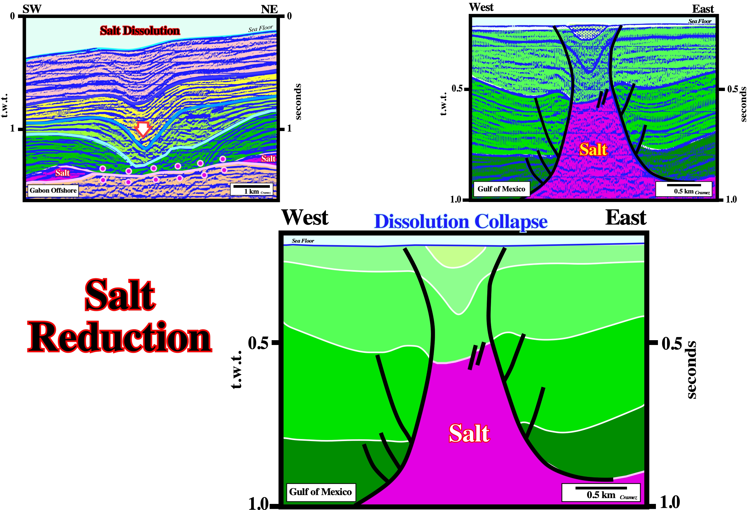
The lateral salt flowage or salt reduction, i.e, the evacuation of the salt created a primary salt weld and a local depocenters in the overburden. The salt reduction, strongly, increased the space available for the sediments (accommodation), which generated three local but obvious depocenters in the synkinematic intervals of the overburden. The light blue interval seems prekinematic.
Salt Ridge
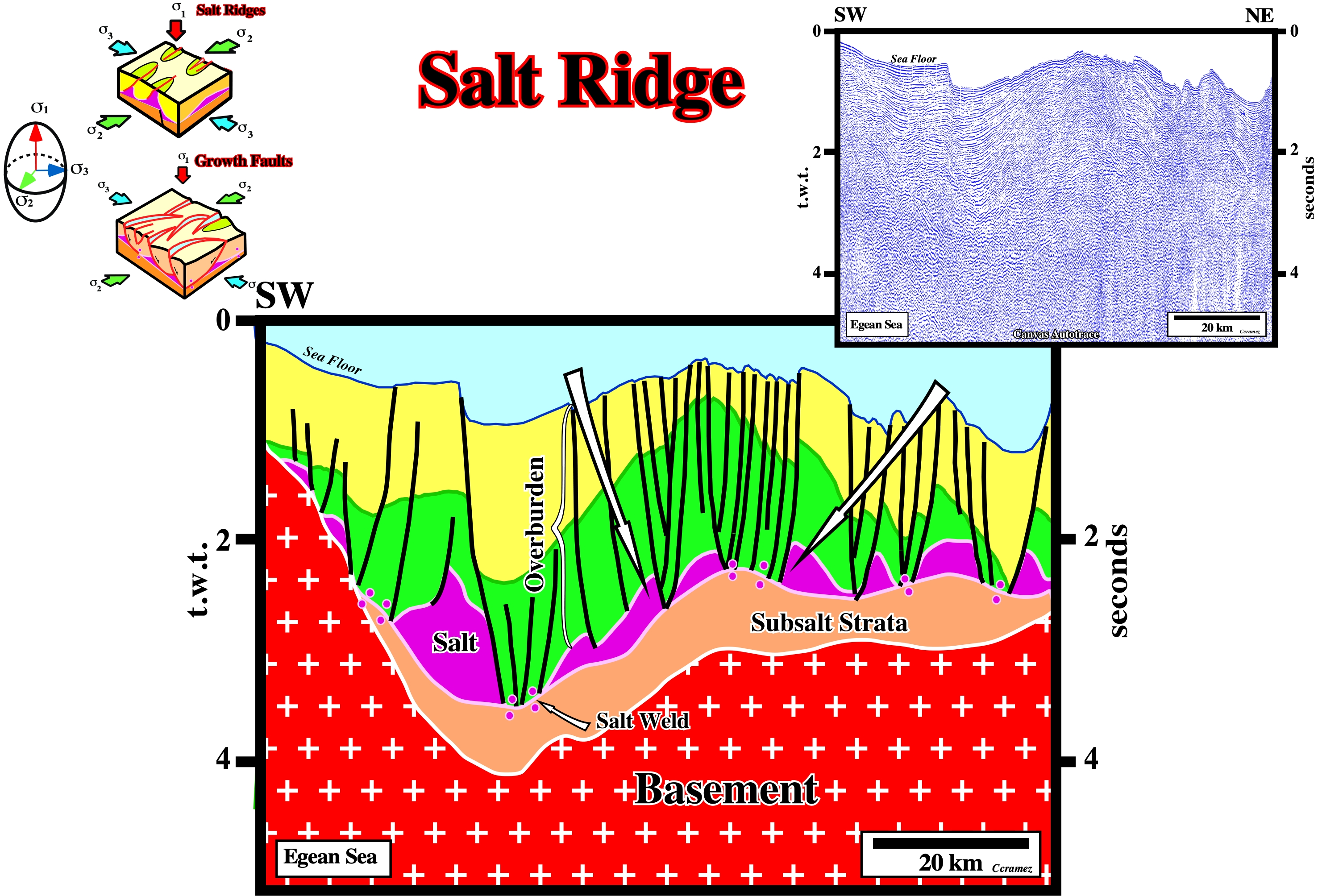
Very often, growth-faults are associated with salt ridges. Generally, it is difficult to differentiate a salt ridge from a growth-fault, when a simple growth-fault developed on a mobile salt substratum. The best criterion, as pictured on the above block diagrams, seems to be the cartographic geometry: (i) Salt ridges have a more or less unbent geometry. The normal-faults associated with them are, more or less, rectilinear. (ii) Growth-faults have a curvilinear geometry. Individually, they create a non-homogeneous extension. The association of an indefinite number of growth-faults is required. At the ground surface and on time contour maps, very often, the cartography of the growth faults is in relay. The maximum extension (maximum throw) of one fault is relayed with the minimum of extension (minimum throw) of the next fault. Such geometry allows homogeneous lengthening (without wrenching). On this subject, it is important to remember that all curvilinear faults (normal or reverse) have a maximum extension (maximum throw) between the ends, where the extension is zero. As illustrated on the above tentative interpretation, the lengthening of the sediments is evident. The tectonic regime is characterized by σ1 vertical. The antiform morphology of the sea bottom is quite significant. The majority of the normal-faults die on the the salt layer (top of the salt) or in the salt induced tectonic disharmony, which often corresponds to a salt weld. The sediments above and below the tectonic disharmony show different deformations. Above it, the cover, i.e., the salt and overburden have been, strongly, extended (the extension still is going on). Below the tectonic disharmony, the subsalt strata are just, slightly, deformed. The cartography of the salt structures, which are bordered by normal-faults, indicates they have a more or less rectilinear geometry. Thereby, they can be classified as salt ridges striking parallel to σ2.
Salt Roller
Low-amplitude, asymmetric salt structure comprising two flanks: a longer, gently dipping flank in conformable stratigraphic contact with the overburden and a shorter, more-steeply dipping flank in normal-faulted contact with the overburden. Salt rollers are an unequivocal sign of regional thin-skinned extension perpendicular to the strike of the salt rollers.
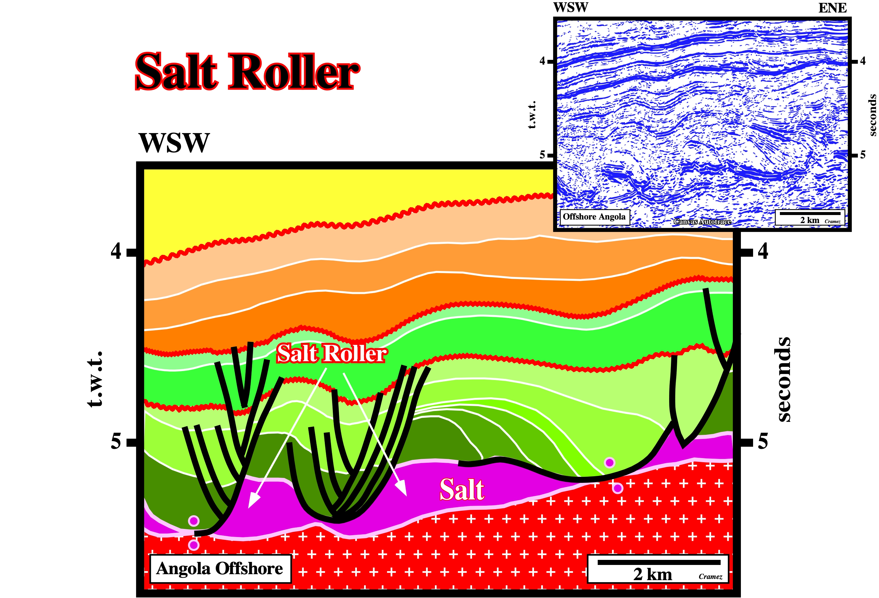
Salt rollers are characteristic of pre-raft domain. Generally, they are assumed to be located in upper continental slope or platform. This Canvas autotrace comes from a seismic line of Angola offshore, where salt rollers are quite obvious. Such an occurrence has important implications for the origin of the high quality calcareous reservoirs.
Salt Sheet
Allochthonous salt whose breadth is at least 5 times its maximum thickness.
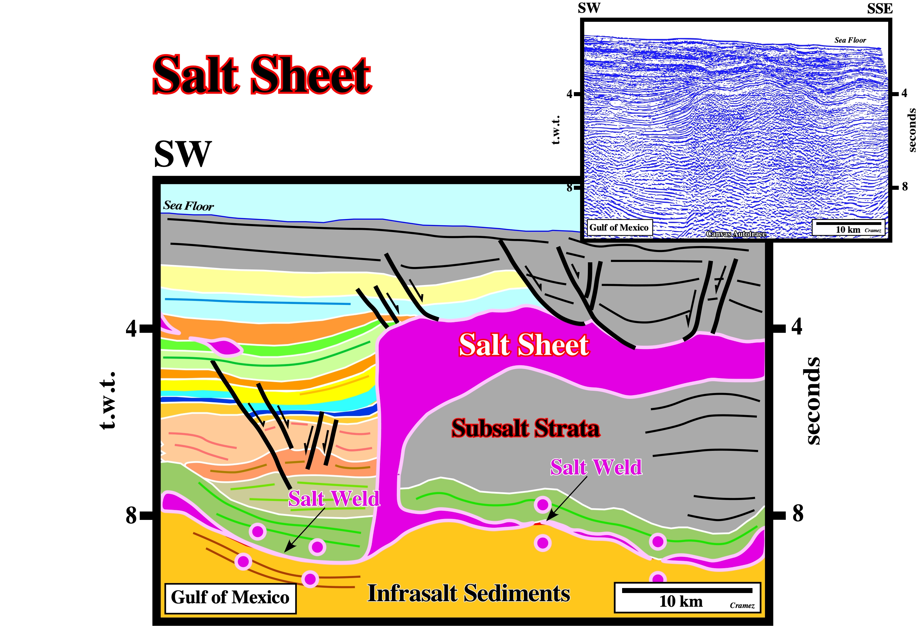
This salt sheet still is connected with the mother source layer, which is, partially, represent by primary salt welds. The feeder or the ramp, which later can become a counter-regional fault, is well recognized. On the top of the salt sheet (breadth > 5 times its maximum thickness) illustrated on this tentative geological interpretation of a Canvas autotrace of a GOM seismic line, several Roho faults dipping seaward are recognized. The two normal faults dipping westward (continentward) are not considered as counter-regional faults, but rather as conjugated faults of the Roho system. Any thickening of the hangingwall of seismic interval is evident.
Salt Sill (Jackson, M.P.A. and Talbot, C.J, 1991)
Intrusive salt sheet whose ratio of maximum width to maximum thickness (arbitrarly and tentativelly) is >20. That means that salt sill is, generally, seismically invisible due to seismic resolution. It is typically intruded at depths of only a few hundred meters or less. Its upper contact is typically concordant, whereas its lower contact is commonly slightly discordant.
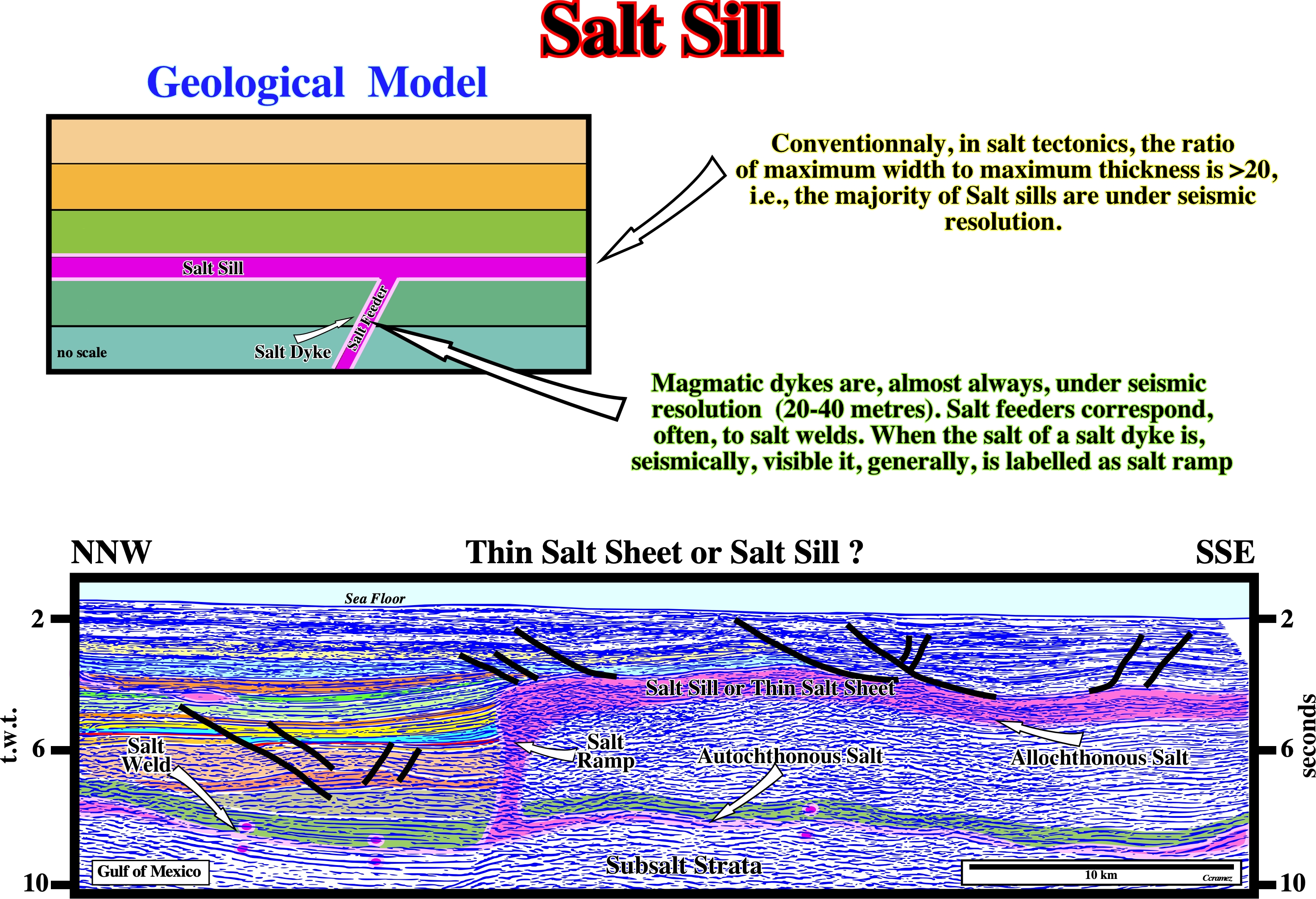
In geology, a sill (or vein layer) is a layer of often horizontal rock that has infiltrated between older layers of sedimentary rock. The infiltrated rock is, generally, magmatic, but can, also be a salt rock. A dyke, or dike, is a vein of rock that has been injected into a fracturing or weak zone of the surrounding rock. As a result, a dyke cuts across the other rocks, it crosses them (unlike a sill). Generally, the injected rock is magmatic, but is can also be a rock salt. The majority of the salt feeders than connected the mother source rocks (autochthonous salt) with the allochthonous can be considered as salt dykes (depending of the salt thickness in relation to the seismic resolution. In field geology, the thickness of a sill, rarely, is higher than 20 meters, ii.e., in conventional seismic data a sill cannot be recognized. A salt sill to be recognized on seismic line must have a minimum of thickness between 20 and 40 meters depending of the seismic data. Said in another way, when a geoscientist recognize on a seismic line a salt sill, the more likely is that he recognized a thin salt sheet, as illustrated on the above tentative interpretation.
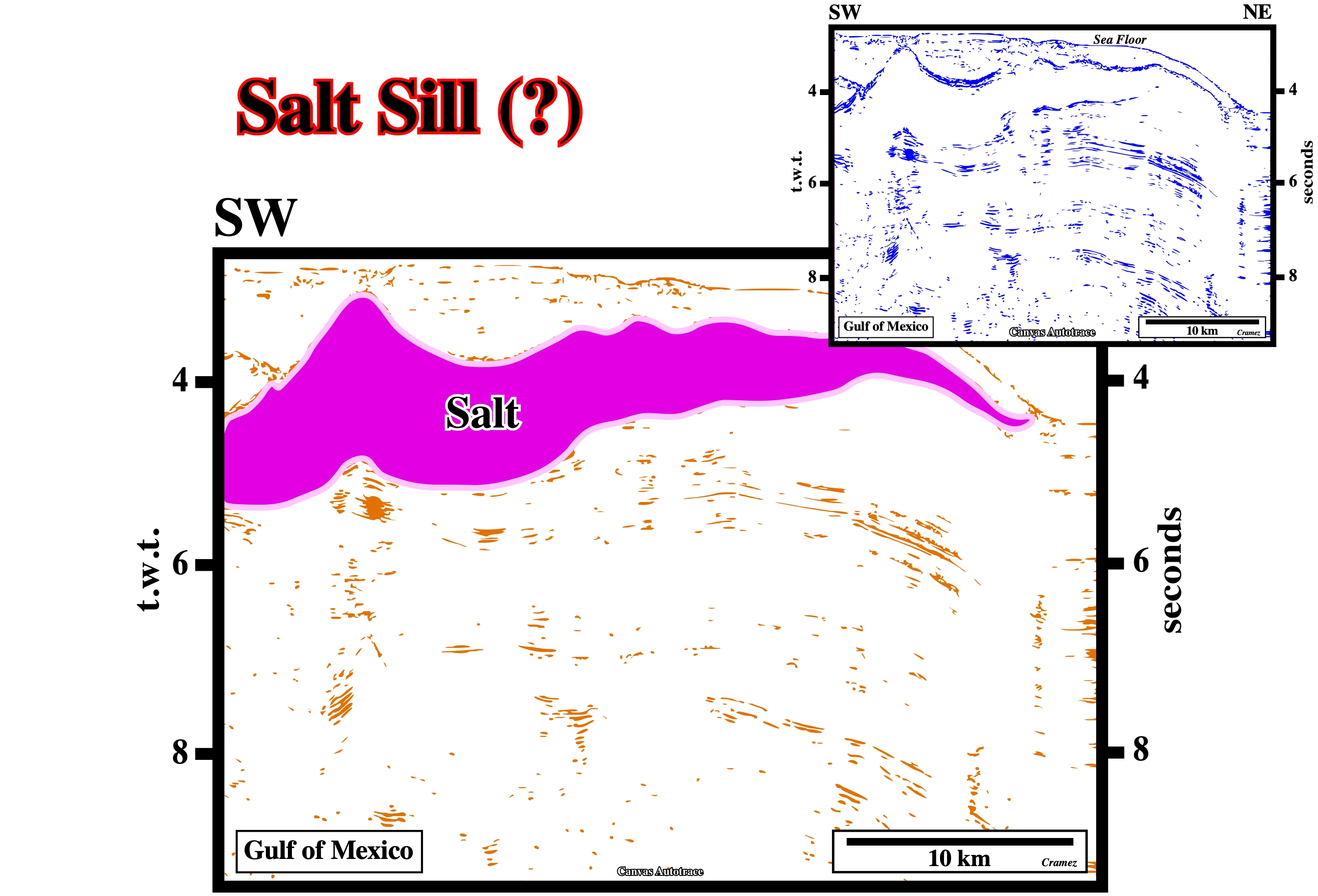
Taking into account this preliminary tentative geological interpretation of a Canvas autotrace of a GOM seismic line is in time and the horizontal scale is 10 kilometers, probably, just the outermost part of this salt body can be considered as a salt sill (ratio of maximum width to maximum thickness is >20). A depth version of the original seismic lines can solve the doubt . At the bottom of this salt sill (i) basal cutoffs, (ii) salt flats are easily recognized. Westward of this allochthonous salt body, ramps or salt feeders must exist, since it must be connected (salt ramps) or disconnected (salt feeder or secondary salt welds) with the mother source layer (autochthonous salt).
Salt Source Layer
Layer supplying salt for the growth of salt structures. Synonym of mother salt.
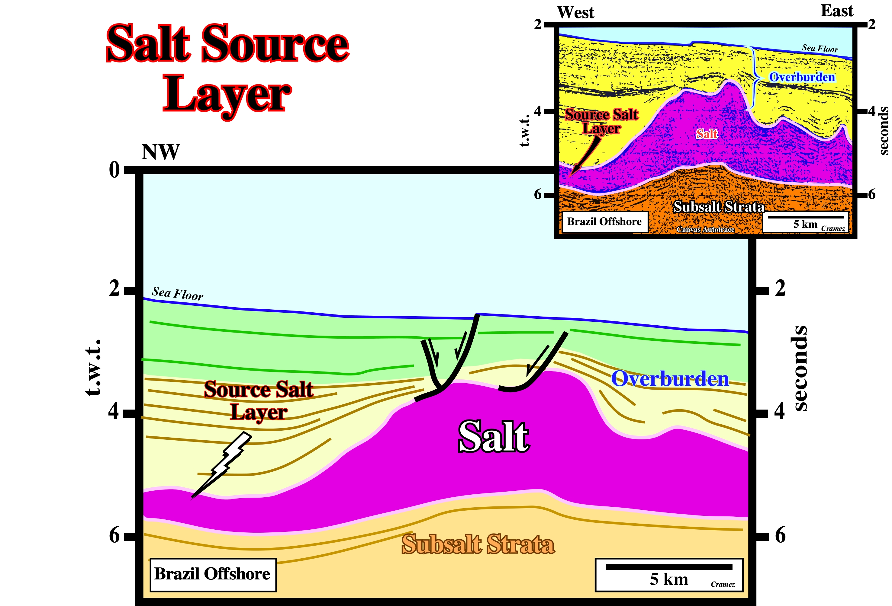
In the Brazil offshore, from where the seismic line of this Canvas autotrace comes, the source salt layer, i.e., autochthonous salt overlies the potential source rocks. Contrariwise to West African salt geographic basins, where the major marine source-rocks are in the overburden. Reason why the organic matter the potential marine source-rocks reached, rarely, the oil window. As illustrated on this tentative interpretation, in this area of the Brazil offshore the overburden is relatively thin. Its maximum thickness is around 3 seconds.
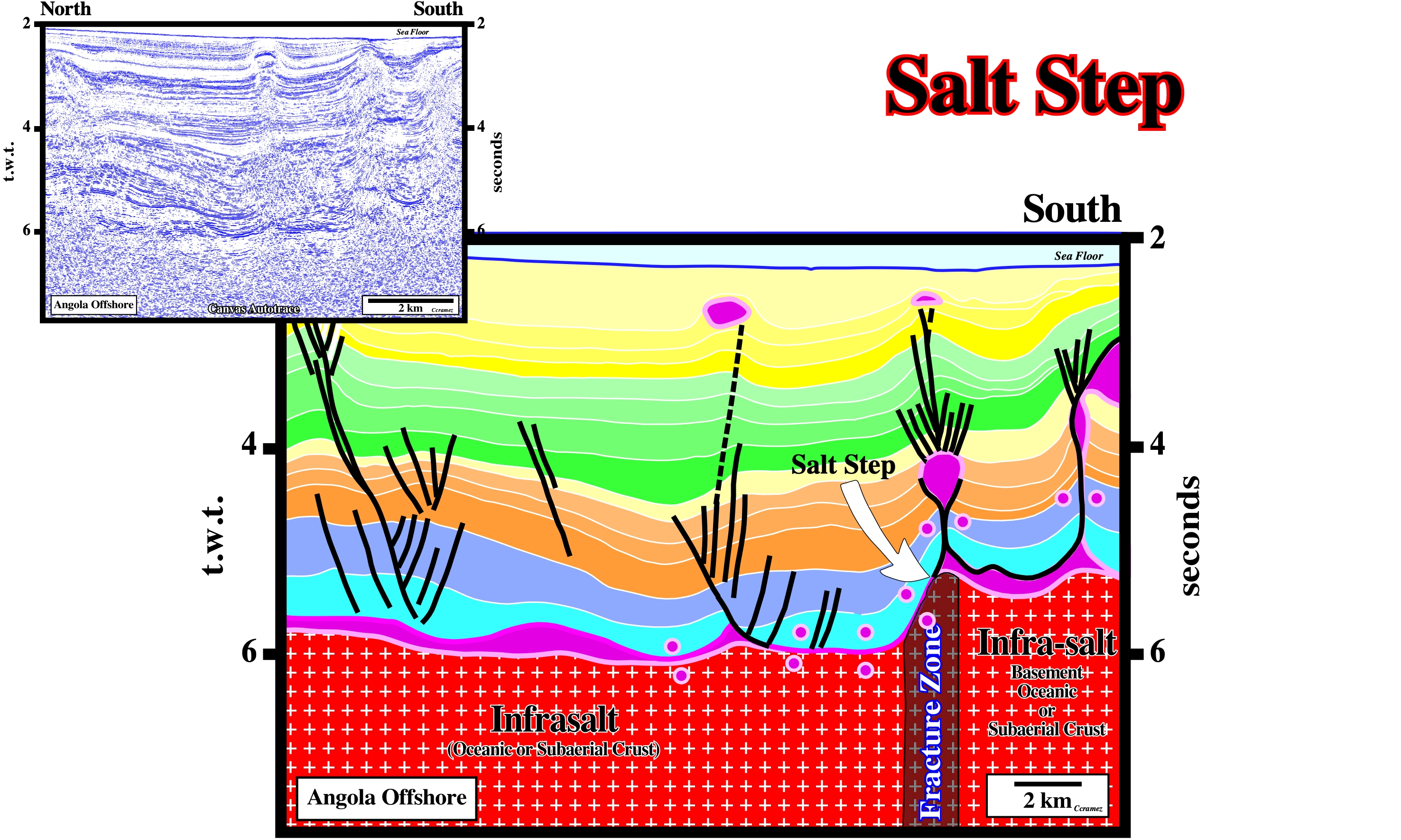
Salt Step
See: Basement Step.
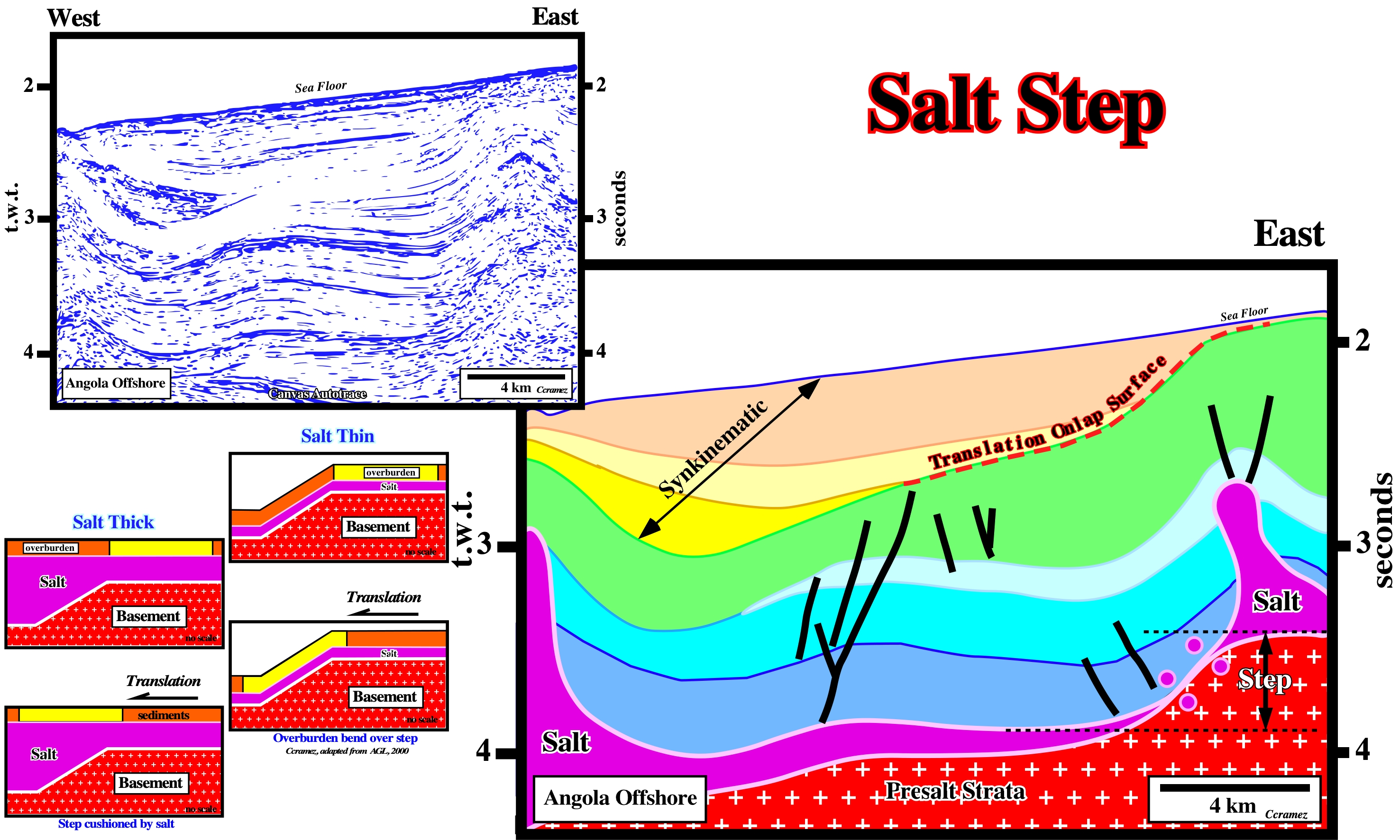
As illustrated on this Canvas autotrace (Angola offshore), when the salt is thick (see geological sketches), a step at the bottom of the salt is, often, cushioned by the salt itself and thereof the overburden is translated basinward without deformation. When the salt is thin, a prekinematic overburden layer may bend over the step, since the salt thickness cannot cushion it. The apparent downlap surface on the translation onlap surface, created by translation of the overburden across a single emergent step, at the bottom of the salt, recognized on this tentative interpretation, is quite characteristic. In spite of the fact that it is, directly, associated with a salt step, its genesis is quite different than that of a salt weld.
Taking into account the orientation of the seismic line of this Canvas autotrace, which is, more or less, perpendicular to a potential basinward translation of the overburden, it is possible that a translation onlap surface is masked. Another possibility is that basinward translation did not occur in this area. However, the salt step associated with the major fracture zone of the basement is clearly recognized. On this subject, it is interesting to note that the salt steps recognized in Angola and Brazil offshore seem to correspond to the fracture zones separating the different geological provinces of the South Atlantic margins (see next figures).
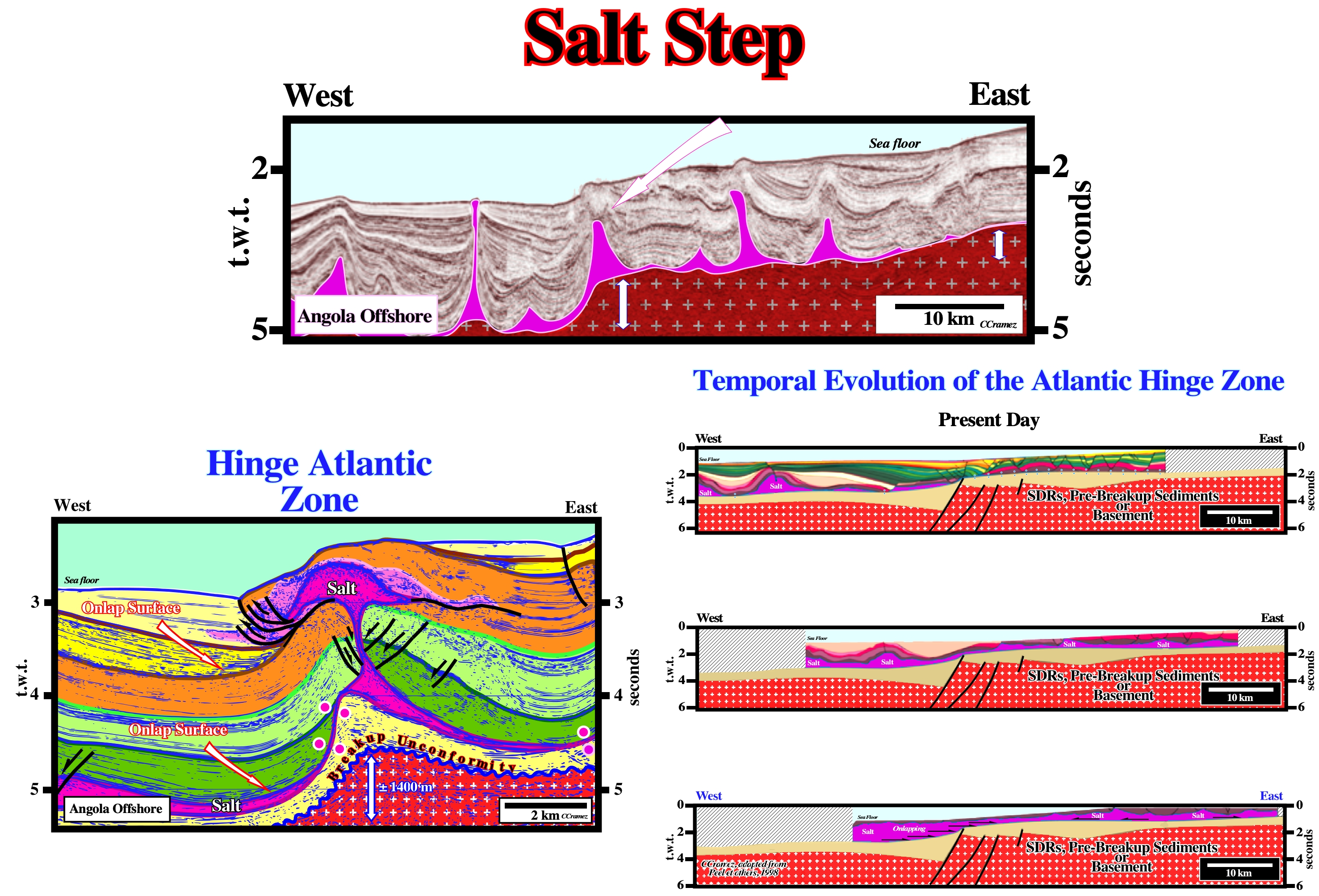
On these geological tentative interpretation of a Canvas autotrace of Angola deep offshores, the major step, on the top of the infrasalt sediments, separates the outer Kwanza geographic basin from the coastal arch and the Atlantic hinge zone. It is characterized by an onlap surface of the evaporites , over the unconformity (erosional surface) developed at the top of : (i) Margin infrasalt sediments (if they exist) ; (ii) Subaerial lava flows postdating the breakup unconformity ; (iii) Rift-type basin sediments or (iv) Basement. As sedimentation takes place above the salt, the salt starts to move seaward. If the sedimentation rate is insufficient to cover the bathymetric escarpment, the sediments onlap above the step and are translated basinward after deposition, producing a landward dipping package of onlapping strata. The distance from a given onlap to the step records the amount of translation. Presently, the seismic lines westward of the Atlantic hinge zone, clearly, illustrate a landward dipping sedimentary intervals onlapping the intervals deposited, immediately, above the salt (upper sketch). The proposed reconstitutions (middle and lower sketch) strongly suggest not only a significant seaward depocenter, but an onlapping of the salt fossilizing the different pre-salt step.
Salt Stock
Pluglike salt diapir with subcircular planform. Synonym of salt plug.
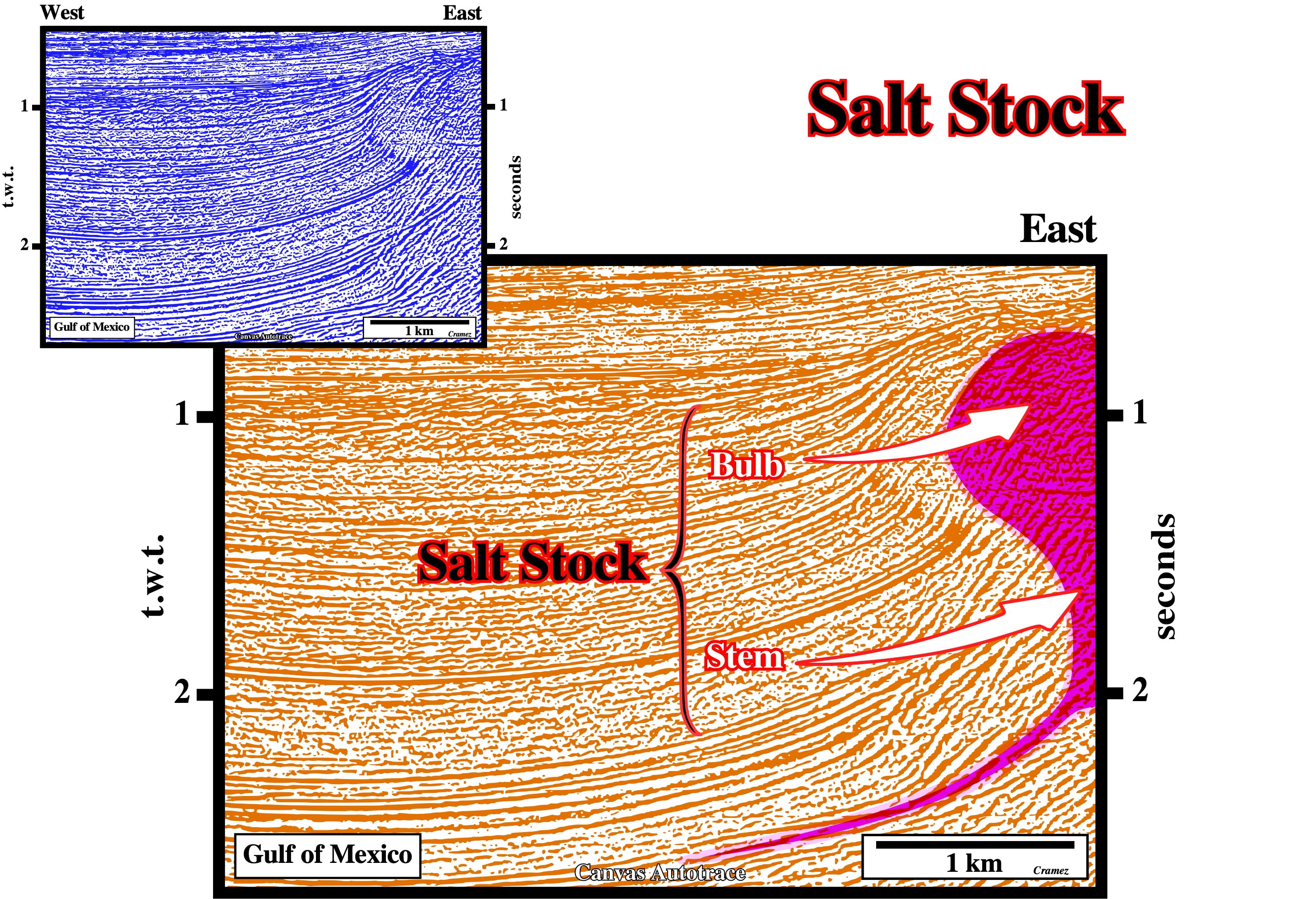
Salt stocks are formed by a stem and a bulb. They can be connected or disconnected of the mother source layer. When disconnected a vertical salt weld is formed (secondary salt weld).
Salt Stock Canopy
Salt Canopy formed by coalescence of Salt stocks.
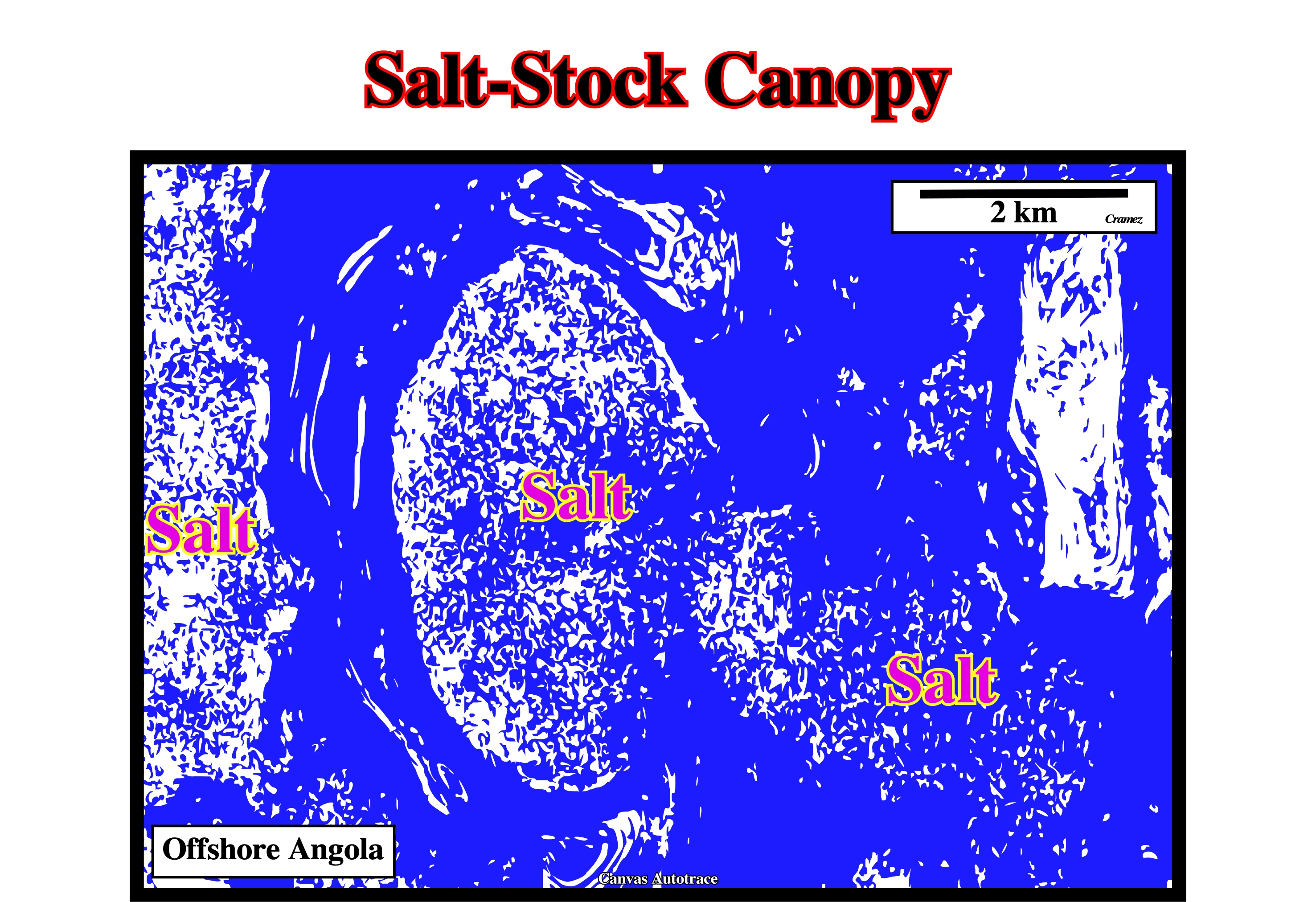
The salt sutures between the different salt stocks to form a salt-stock canopy still are easy recognized on this time slice, which depth is less than 0.5 second below sea floor.
Salt Suture
Junction between individual salt structures that have coalesced lateral to form a canopy.
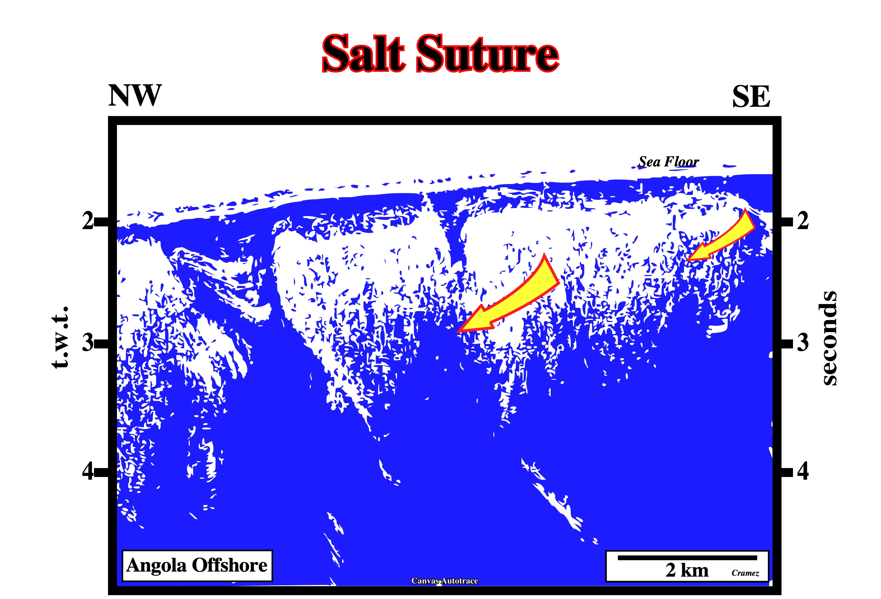
Allochthonous salt sheets or salt stocks can gathered to form large salt napes or salt-stock canopies. Here, it is obvious that salt-stocks are coalescing to form a salt-stock canopy.
Salt Swell
Generally, a synonym of Salt Pillow. However, some geoscientists used this term, parrticularly, when the salt structure is induced by a compressional tectonic regime rather than salt flowage.
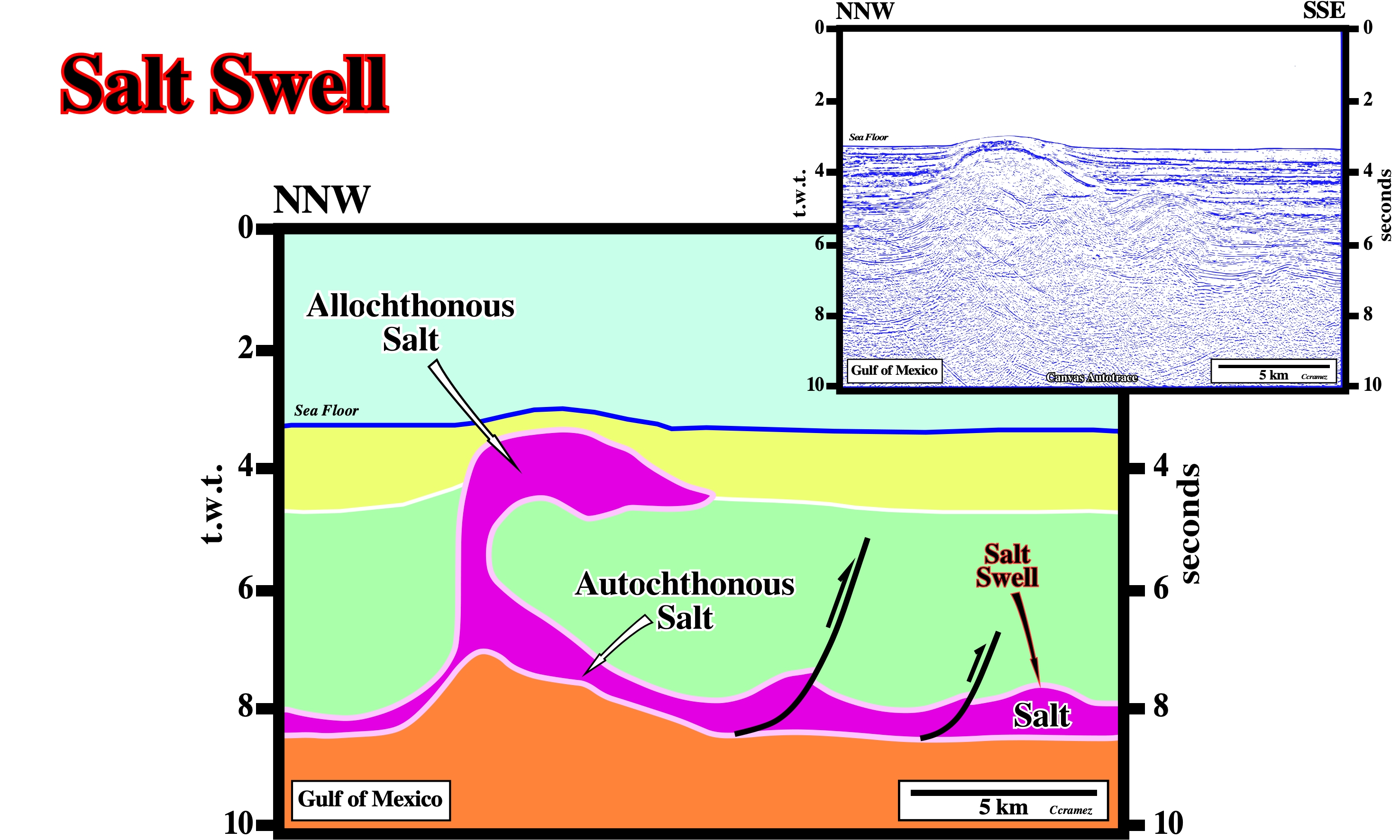
Taking into account the geometrical relationships between the seismic reflectors, as well as, the seismic surface defined by the reflection terminations, on this tentative geological interpretation of a Canvas autotrace of a GOM seismic line, the top of the allochthonous salt can be considered as a salt swell induced by a compressional tectonic regime that shortened and uplifted not only the salt but, also, the overburden, clearly, deforming the sea floor. The different tectonic phases can be recognized since the top of the green interval corresponds to a tectonically enhanced unconformity.
Salt Tectonics
Any tectonic deformation involving salt or other evaporites, as a mobile layer. In this sense, salt tectonics is not a synonym of halokinesis, which labels a sedimentary deformation powered entirely by gravity, i.e., by buoyancy, in absence of significant tectonic stress (σt = 0), i.e., in an equilibrium tectonic regime. Halokinesis is, often, associated with an extensional tectonic regime (lengthening, σ1 vertical), but rarely with a compressional tectonic regime (shortening, σ1. horizontal).
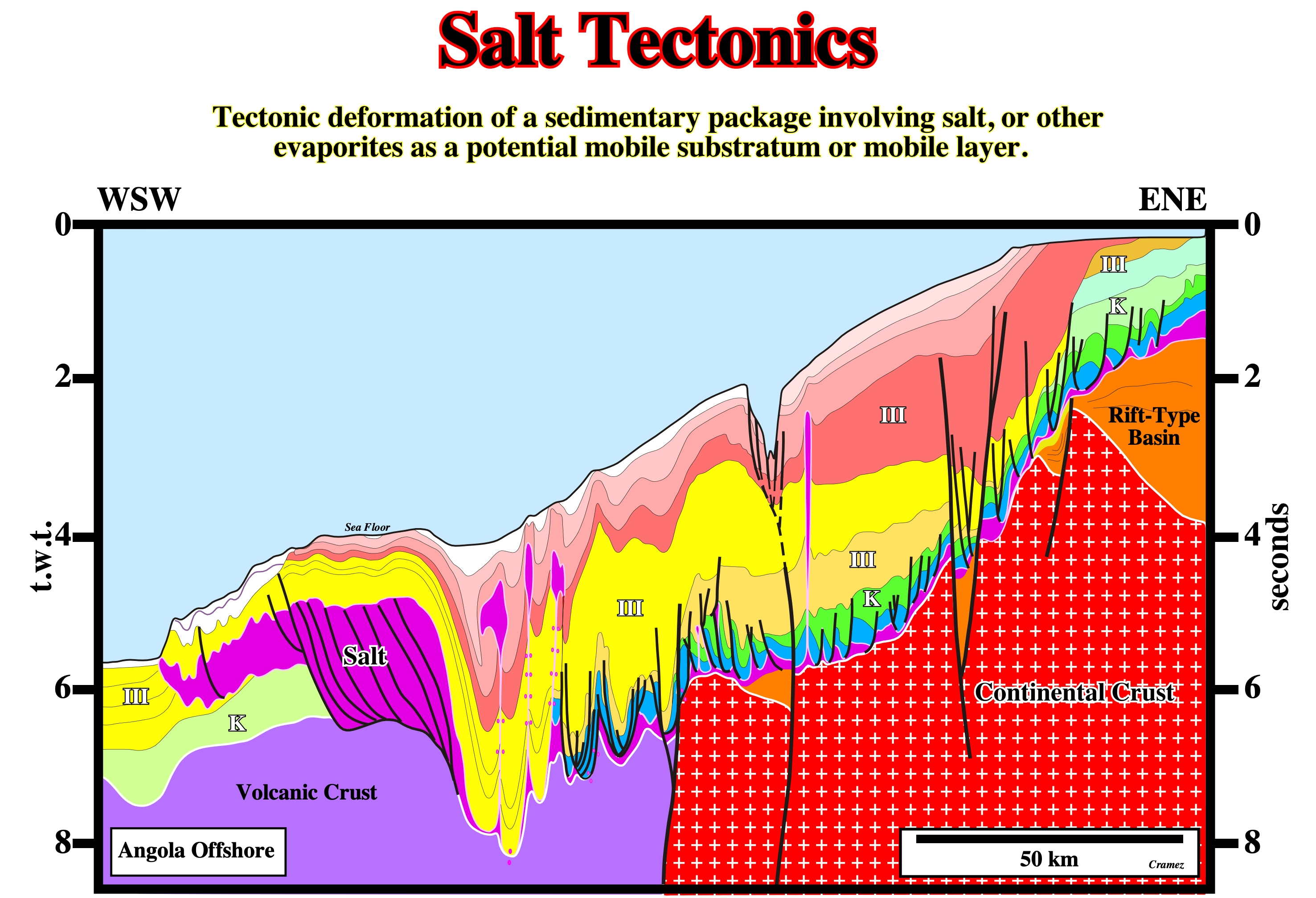
Some geologists used the term salt tectonics when an extensional tectonic regimeis active and halokinesis when salt deformation take place in absence of a significant tectonic stress. In certain basins a significant salt layer, as illustrated on this regional geological cross-section based on tentative geological interpretations of Canvas autotraces of Angola offshore seismic lines, at a regional scale, i.e., at the macroscopic scale (scale of the basin), extensional and compressional tectonic regimesare present. Locally, almost all salt structures can be explain just by halokinesis. However, at the scale of the basin, halokinesis plays a secondary if not a meaningless role.
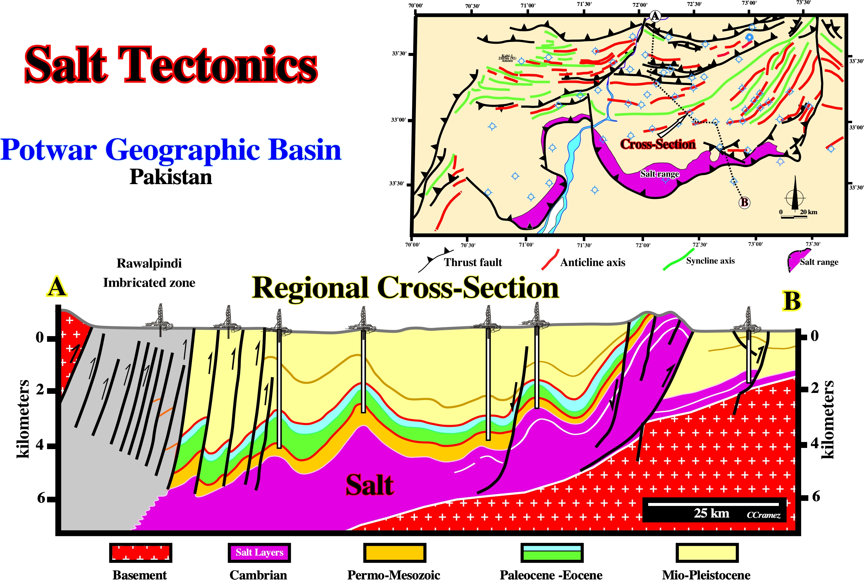
In Potwar (or Punjab) geographic basin (Pakistan), which, in Bally’s classification of sedimentary basin, is considered as a folded belt associated with an A-subduction zone (Ampferer), i.e., a basin located within the Ceno-Mesozoic megasuture, the predominant tectonic regimes are compressional. All sediments and, partially, the basement, were strongly shortened with formation of large anticline structures with reverse and thrust faults. A decollement surface, above the basement, was favored by the presence of salt layers (Precambrian-Cambrian age), immediately, above the basement. The Salt Range Formation (in purple in the cross-section), which has, here, its typical locality, consists, essentially, of a non metamorphosed sequence of salt, marl, gypsum and dolomite with dominant red gypsiferous claystone without any apparent bedding. The Salt Range formation contains the great mines of Mayo, Khewra, Warcha and Kalabagh, which yield vast supplies of salt. Bituminous shales, dolomite, and oil shale layers are common. As depicted above, the salt layers were shortened in the same way as all other sedimentary packages. In this area there is no evidence of halokinesis, i.e., deformation of the salt layers in absence of a significant tectonic stress (σt = 0).
Salt Tongue
Highly asymmetric variety of salt sheet or salt laccolith fed by a single stem. Individual salt tongues are as large as 80 km long and 7 km thick. Typically applied to wedgelike bodies with large taper angles and which do not resemble a salt sill.
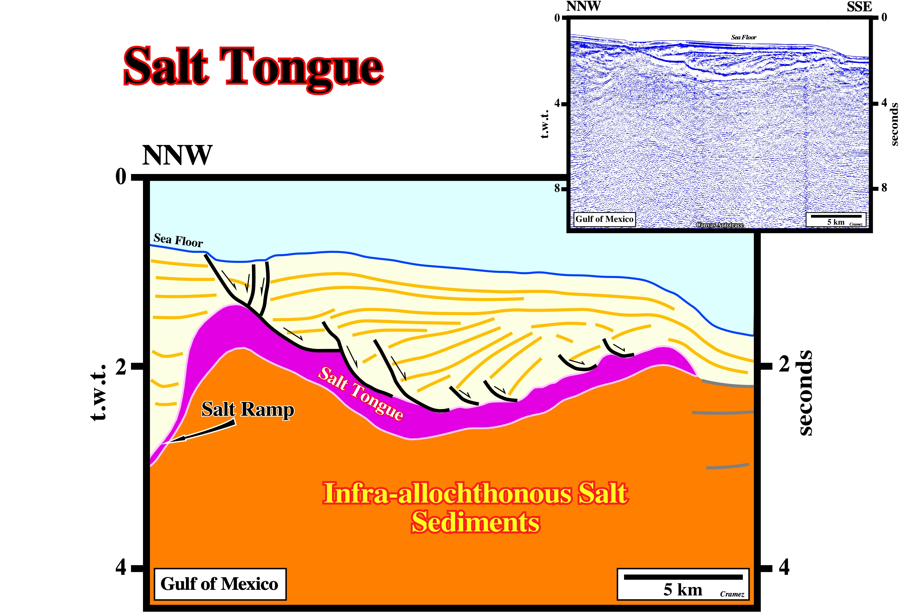
Salt tongues as the one illustrated on this tentative interpretation of a Canvas autotrace of a seismic of Gulf of Mexico are, relatively, difficult to distinguish from salt laccoliths or salt sheets, in addition such a differentiation is nonmeaningful.
Salt Tongue Canopy
Coalescence of salt tongues.
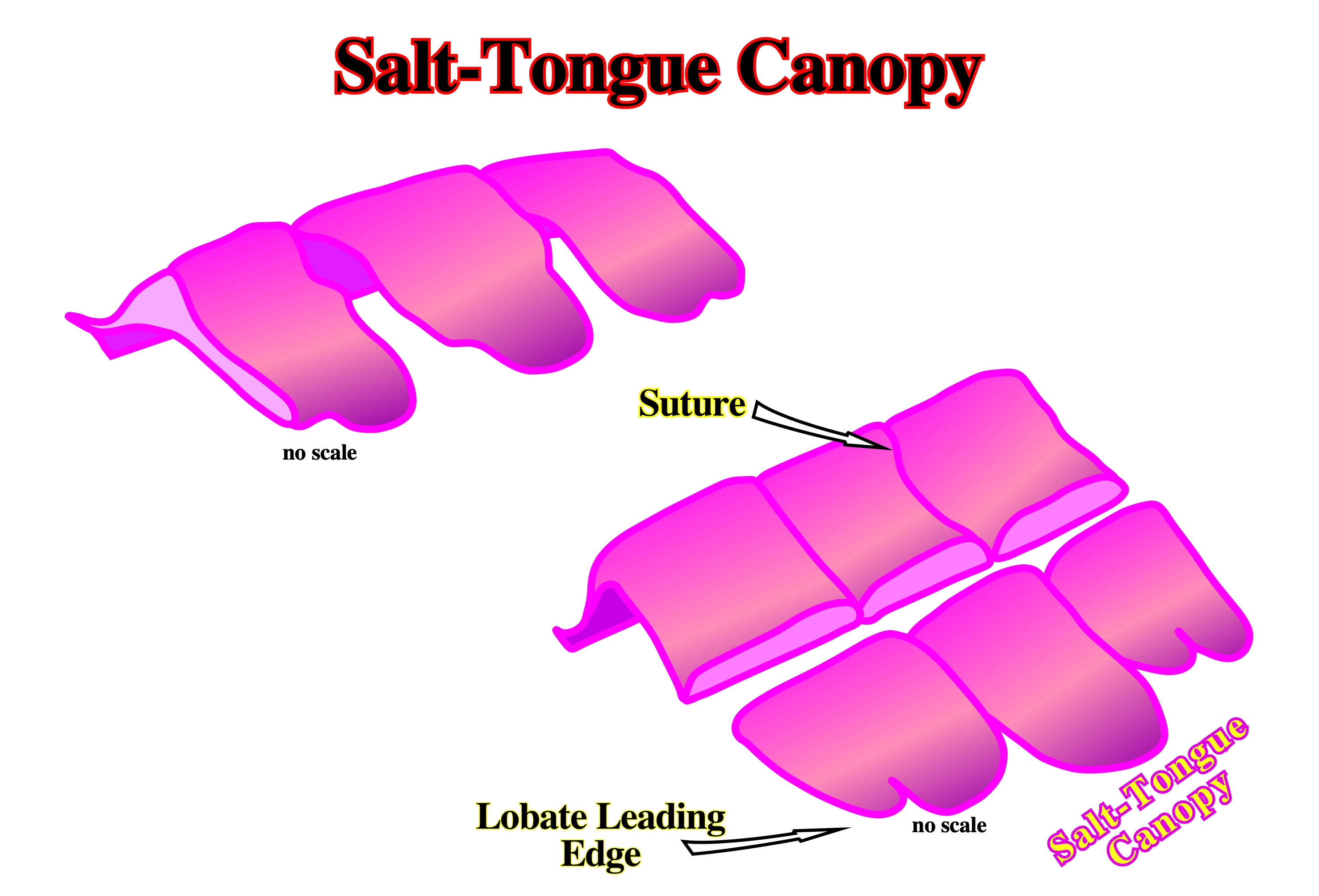
Salt-tongue canopies are quite difficult to recognize on seismic lines. They can, easily, to be recognized on shallow time slices knowing the above geological model. Seismic interpreters can recognize, only, on seismic data what they known, i.e., in seismic interpretation Theory precedes Observation (K. Popper, 1934).
Salt Upwelling
Salt upwelling is, generally, referred to small vertical salt flowage initiated at shallow depths. Salt can flow under quite small overburden thickness as suggested by onlaps, truncations and lateral thickness changes against dome flanks. Reefs are, often, found on dome crests.
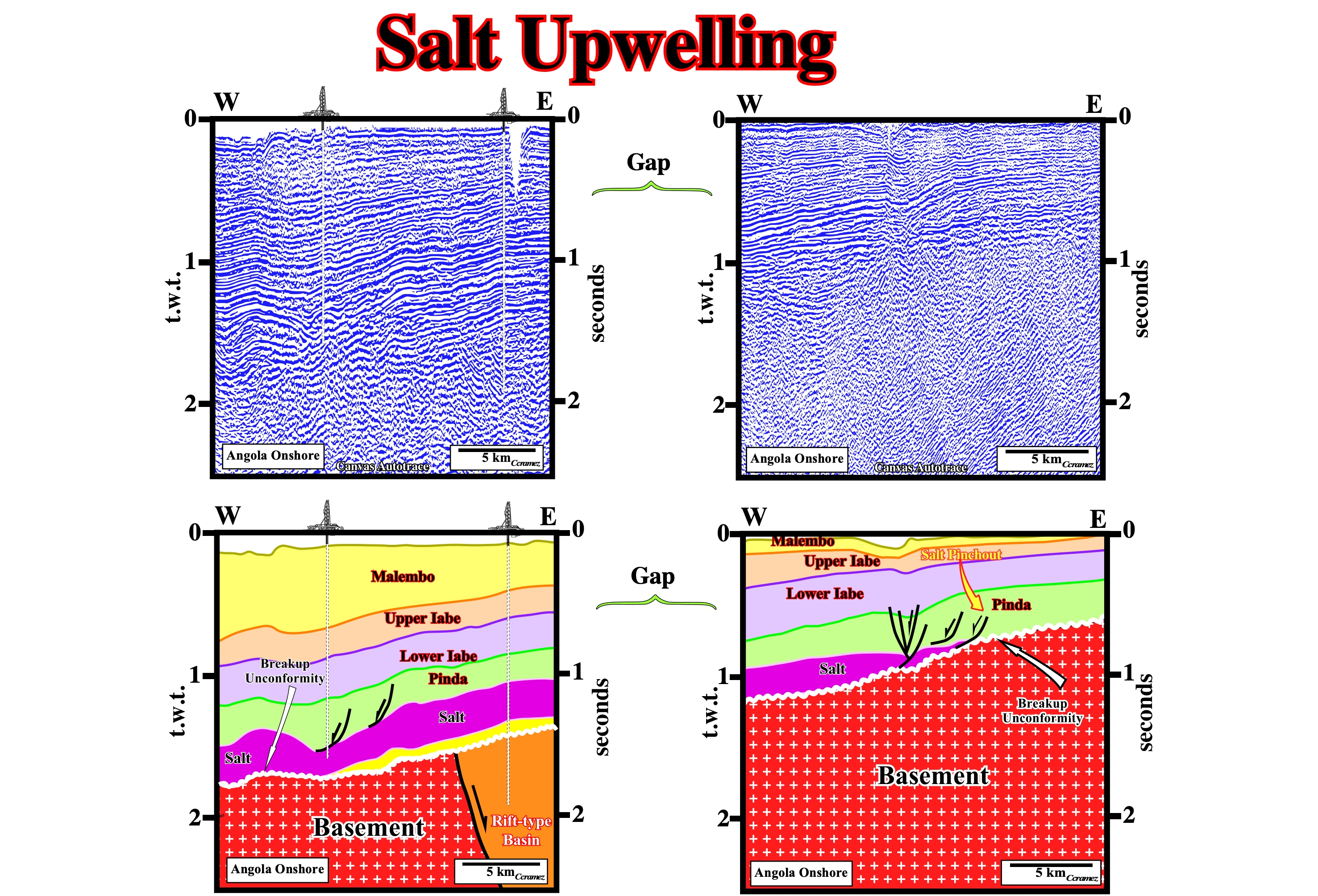
On these Canvas autotraces of Angola onshore seismic lines (South Congo geographic basin), salt upwelling are recognized near the eastern pinchout of the salt, which is here, as in other salt basins, emphasized by a normal fault system. On the eastern autotrace, it is interesting to notice the salt flows under a thin overburden. The subsalt margin sediments are quite well visible above the breakup unconformity in the distal autotrace, which not the case eastward (probably under seismic resolution).
Salt Volume Loss
Synonym of salt reduction.
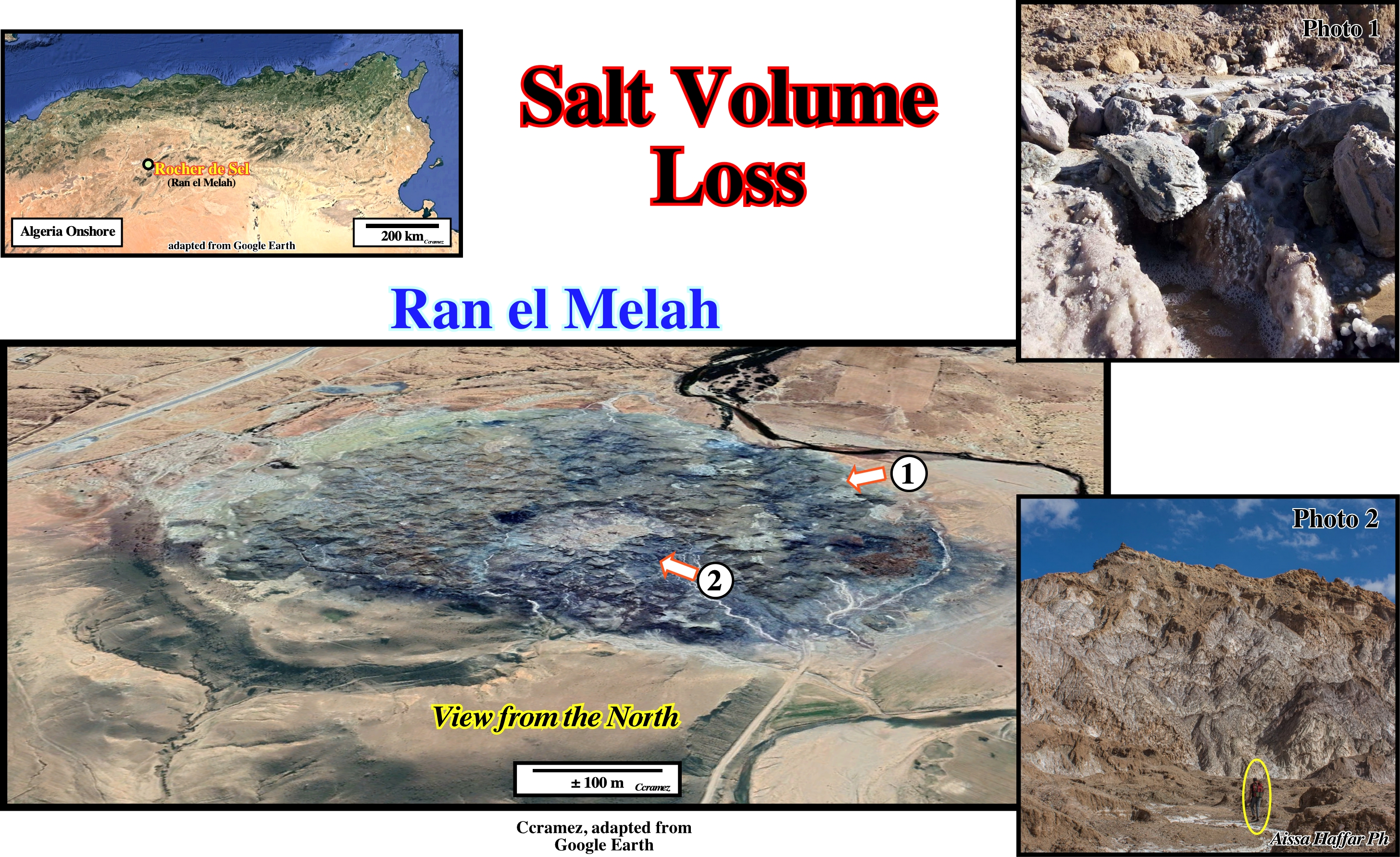
The "Rocher de Sel" , located 25 km north of Djelfa on the National 1, near Ain Maabed and Oued Malah, towards Algiers, is a Triassic diapir, i.e. a rise, generally, of salt or gypsum, which is done thanks to their ductile (deformable) nature and by the pressure of the overlying layers. As said by the old French geologists, to understand what a diapir is , it is very simple: "Walk barefoot in the vase and watch it pass between your toes". in fact the term diapir comes from the Greek "διαπειρα" that means to pierce through. Since a diapir arrives in surface, not only the salt can flow laterally, but it can, also, be severely, dissolved.
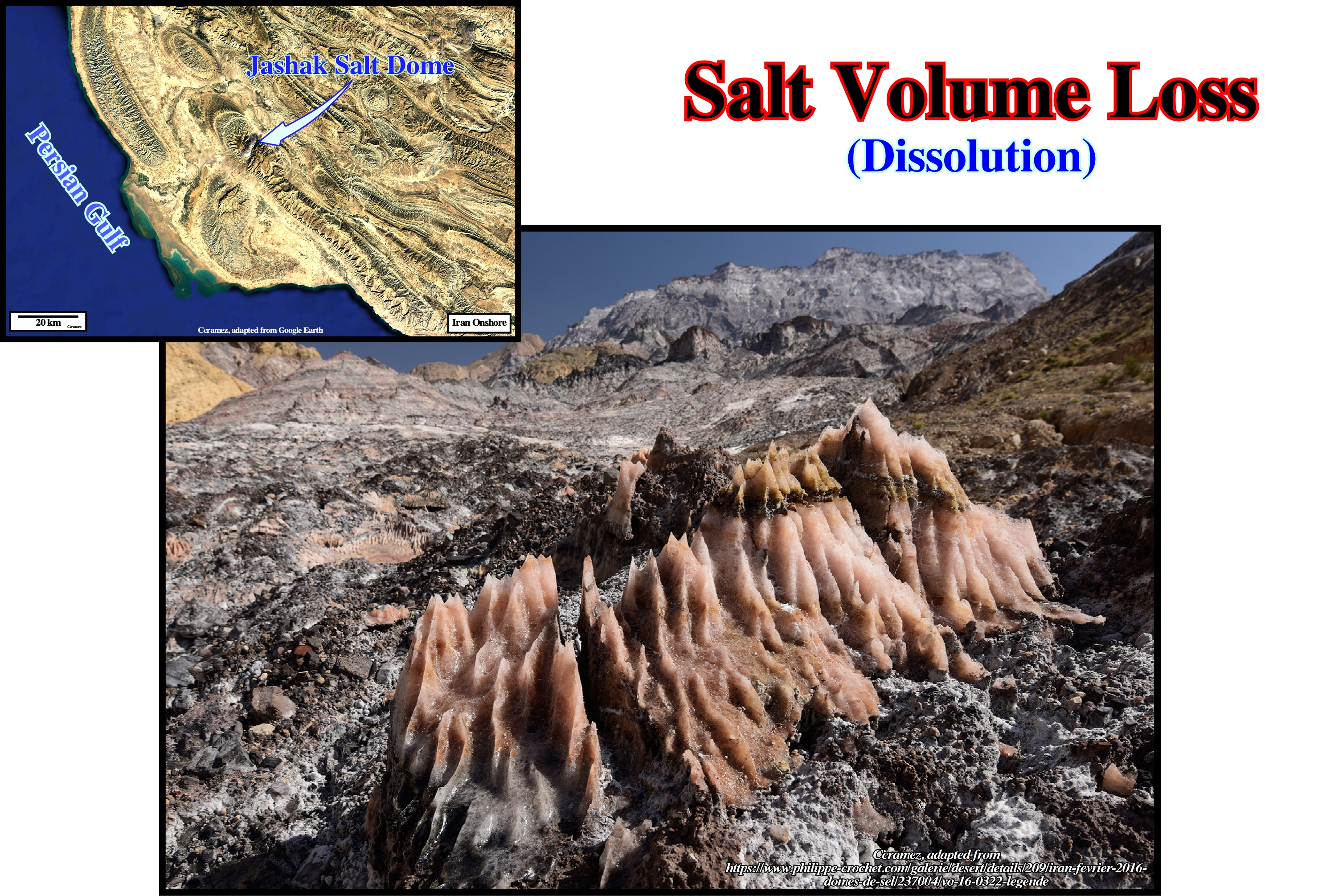
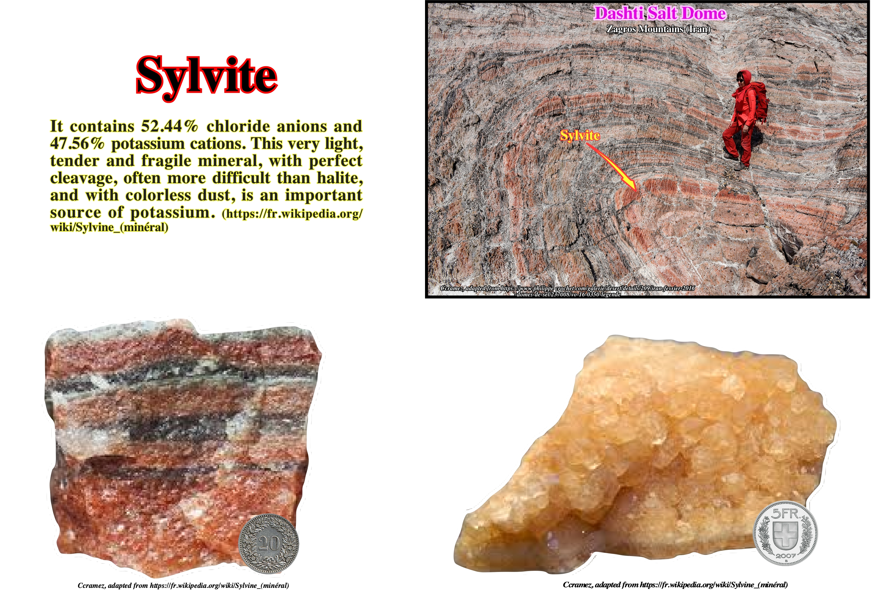
Southern Iran has many salt domes or diapirs, which are among the most beautiful in the world. They are due to the rise to the surface of old salt deposits which are found in depth. This phenomenon, called halokinesis, is made possible due to the low density and ductility (property of deforming without breaking) of the salt compared to the host rocks. The uplift salt can be stopped before reaching the surface (intrusive dome) or pierce it (extrusive dome). In the second case, true mountains of pure salt are formed which are subject to erosion. The of salt being soluble in water, the rain will shape specific and spooky landscapes, with in particular sharp and very hard edges making the progression delicate as illustrated on this photo taken on the Dashti dome in south-eastern Iran, not far from the town of Khormoj (Zagros Mountains). Salt volume losses also creates cavities, as there are more commonly found in limestones. However, these are shorter because the rock is less stable, which results in landslides that can block the underground networks that may have developed.
Salt Wall
Ellongated up-welling of diapiric (discordant) salt, commonly forming sinuous, parallel rows.
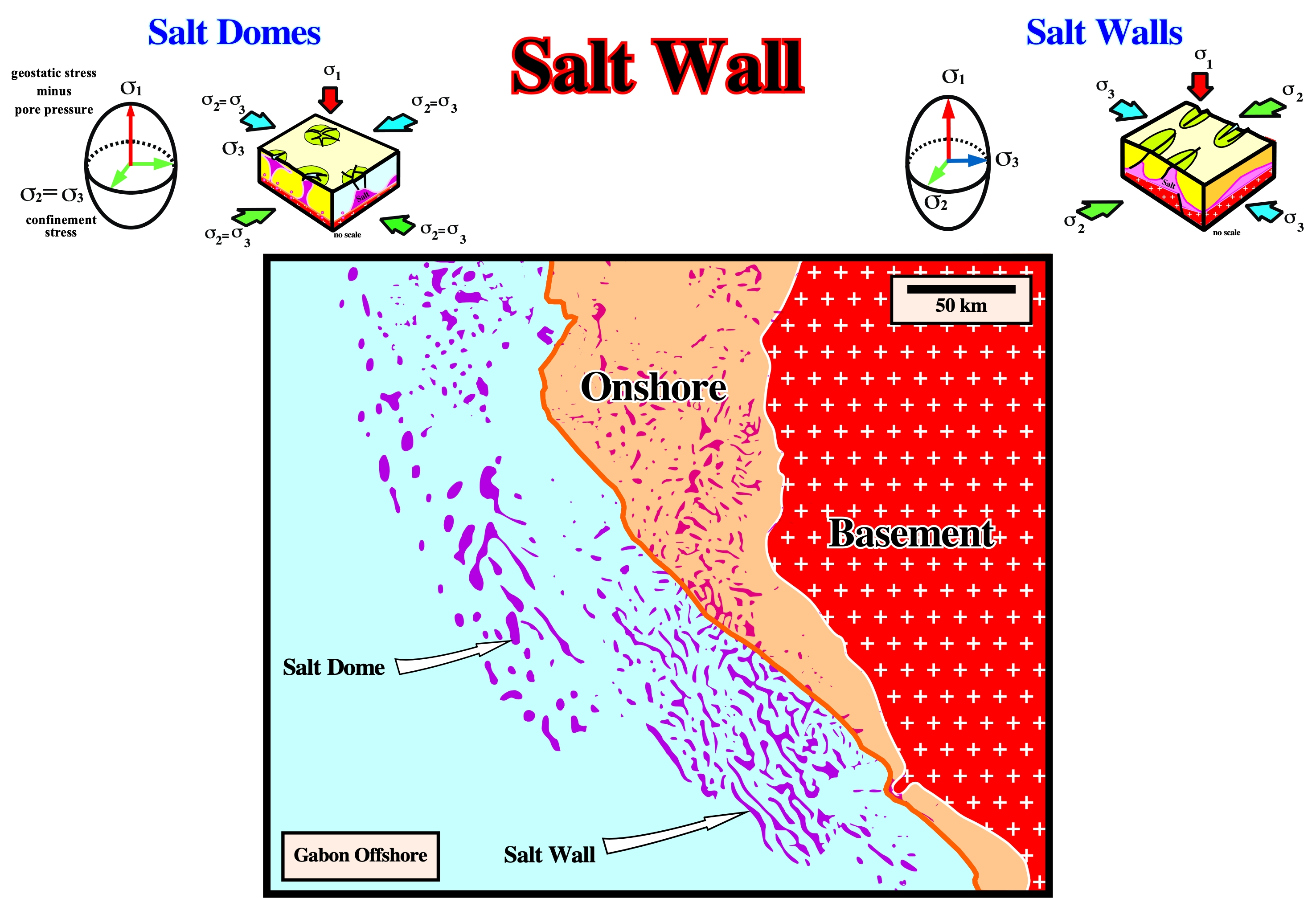
Salt walls are easily recognised on time slices or on geological maps. On this map, the salt structures (in pink) are, mainly, elongated, particularly on the southern part, and they parallel to the shoreline, which corresponds roughly to the σ2 . The minimum effective stress, σ3, is, roughly, perpendicular to the shoreline.
Salt Wall Canopy
Coalescence of salt walls.
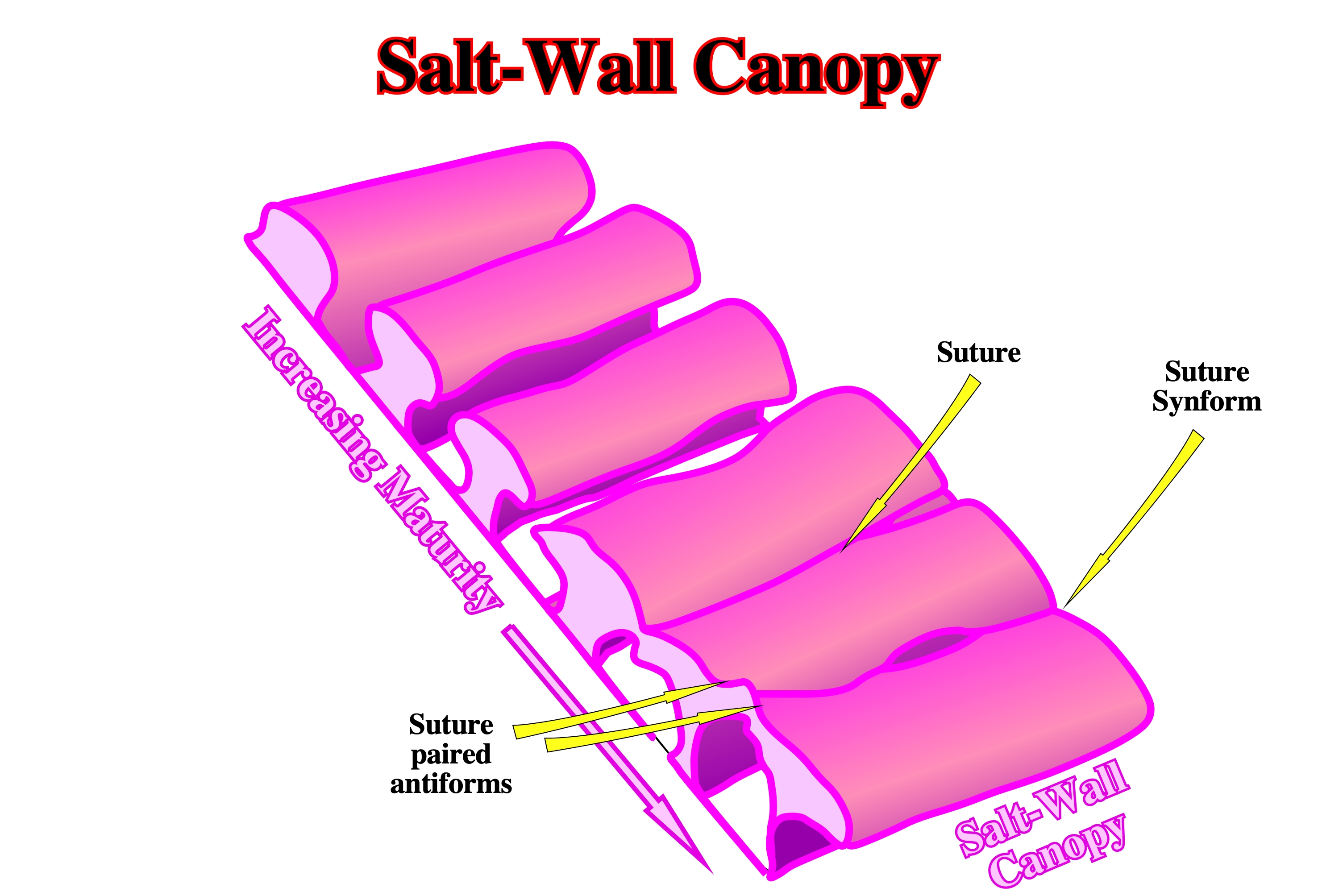
As illustrated above, with time, salt walls can coalesce and form quite large salt wall canopies. Often, time slices allow to recognize the sutures between the different salt walls or the suture synforms, which allow, easily, differentiate salt wall canopies from salt napes.
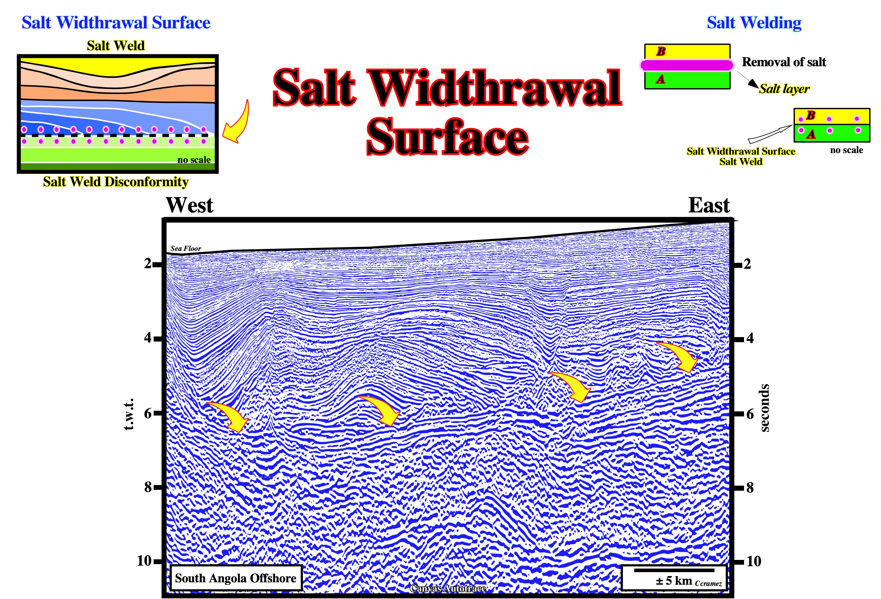
Salt Weld
Surface or zone joining strata or originally separated by autochthonous or allochthonous Salt. The weld is a negative salt structure resulting from the complete or nearly complete removal of intervening salt. The weld can consist of brecciated, insoluble residue containing halite pseudomorphs or of salt too thin to be resolved in reflection-seismic data. The weld is usually but not always marked by a structural discordance. Another distinctive feature of welds is a structural inversion above them.
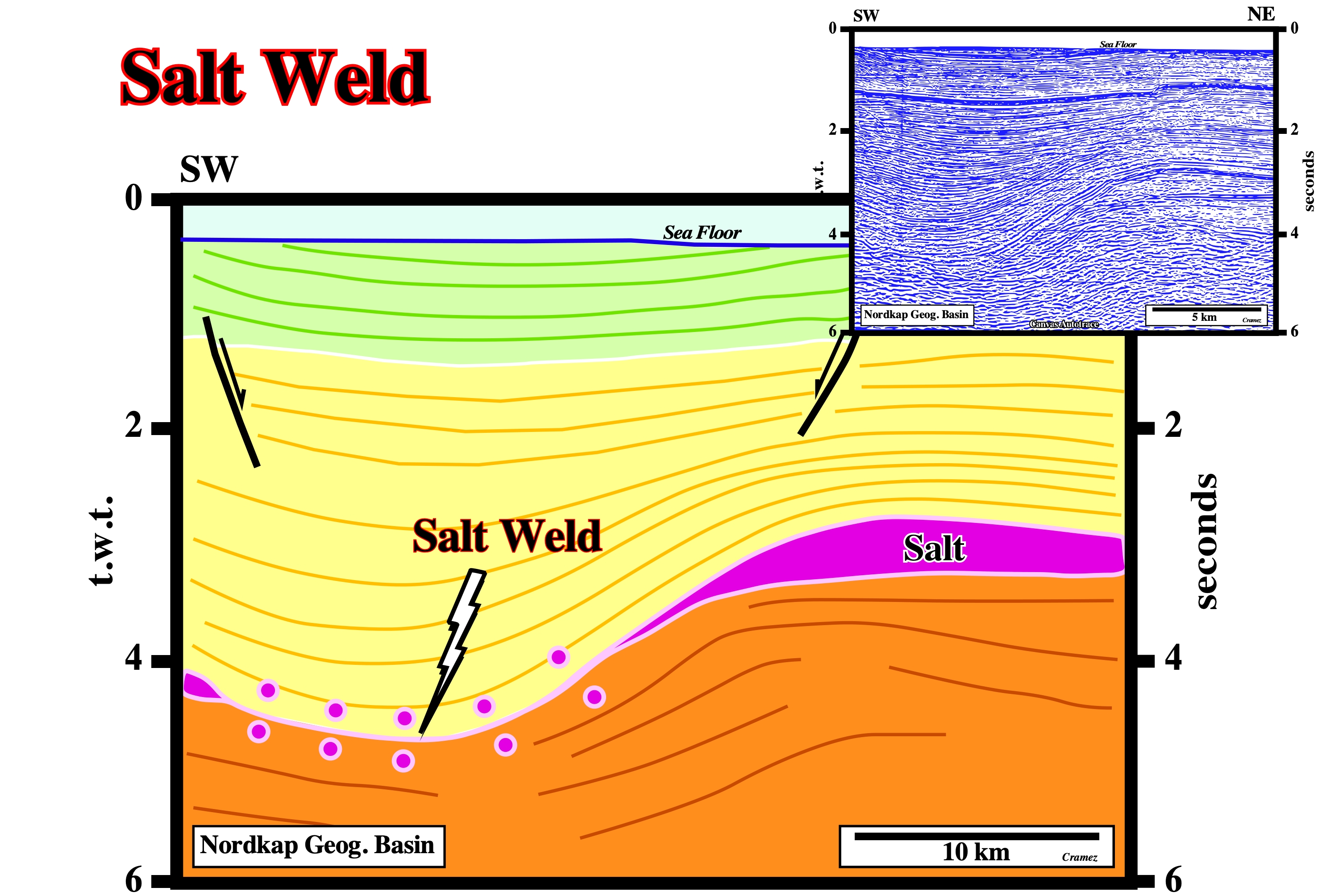
On this tentative interpretation of a Canvas autotrace of a seismic line from the Nordkapp geographic basin, the salt weld is quite obvious. The salt mother layer is recognized in both sides of the salt weld. The depocenter located above the salt weld can only be explained by compensatory subsidence, i.e., by salt withdrawal and lateral salt flowage.
Salt Welt
Synonym of salt antiform.
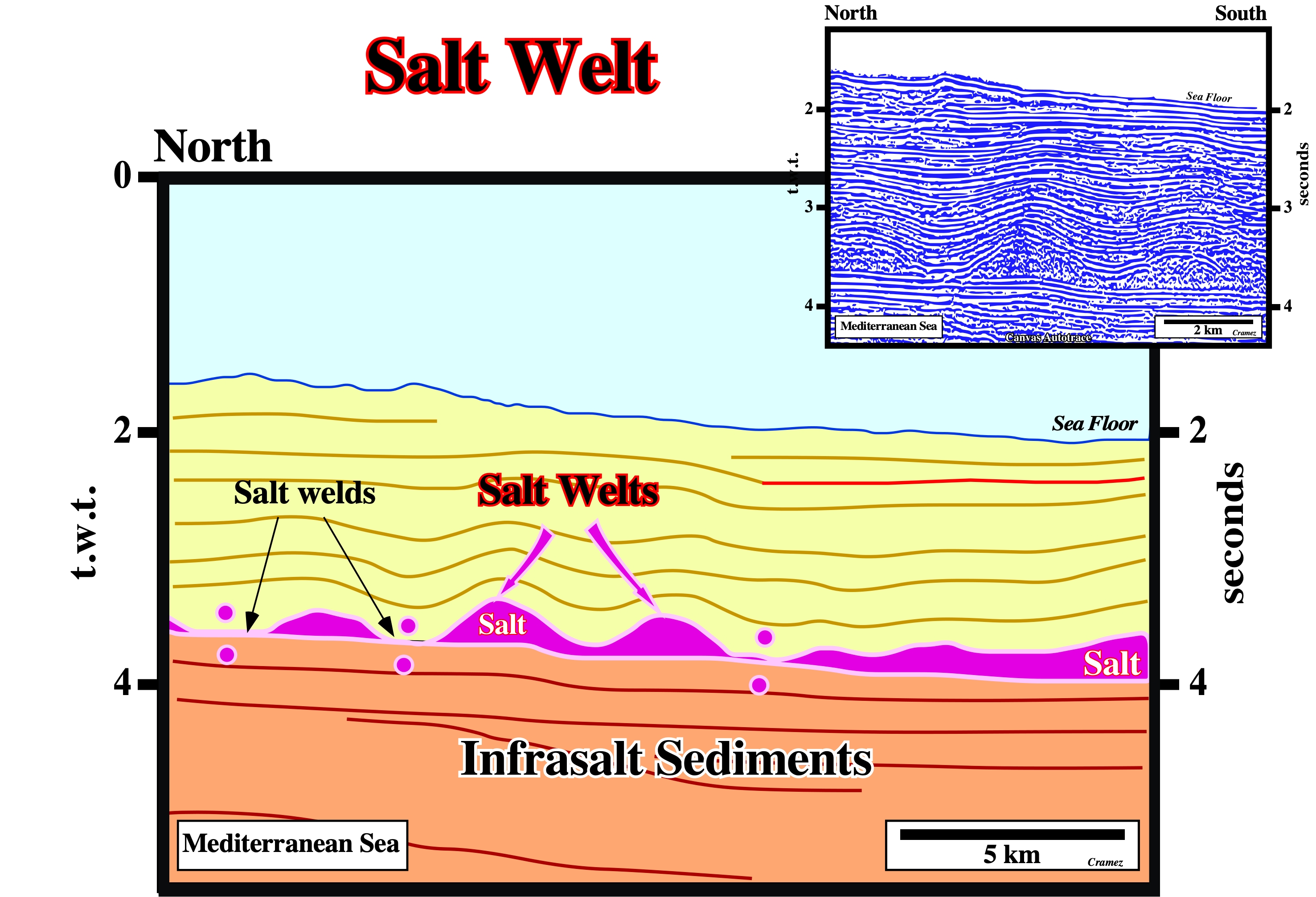
Salt welts are not synonym of salt anticlines. They are extensional salt structures, generally, created by salt flowage. Sometimes, they correspond to salt upwellings, as illustrated on this tentative geological interpretation of a Canvas autotrace of a Mediterranean seismic line. The internal configuration of the lowermost interval of the overburden is divergent toward the synforms, what suggests that it is a synkinematic layer. The salt started to flow at quite shallow depth almost without overburden.
Salt Wing (Diegel, F. A. et al, 1995)
A small salt sheet (allochthonous salt) with a subhorizontal top and base and with a demonstrable base.
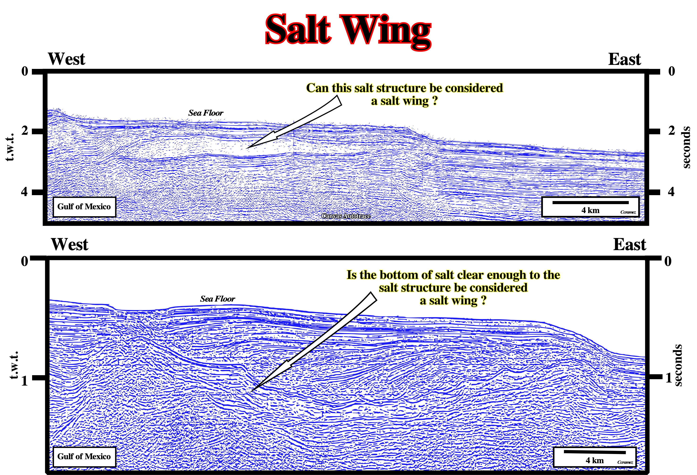
Comparing these Canvas autotraces of two Gulf of Mexico seismic lines, the upper allochthonous salt structure seems to correspond rather to a salt wing, according to the definition proposed above, than the lower one, on which the top and base of the salt are not subhorizontal. Both salt structures control, partially, the morphology of the sea floor.
Salt Withdrawal
Mass transfer of salt over time without obvious change in salt area in cross-section. Examples are the migration of salt from the flanks of a salt pillow into its core as it evolves into diapir or the flow of salt along a salt wall into local culminations that evolve into salt stocks. In a certain sense salt withdrawal can be considered a salt reduction.
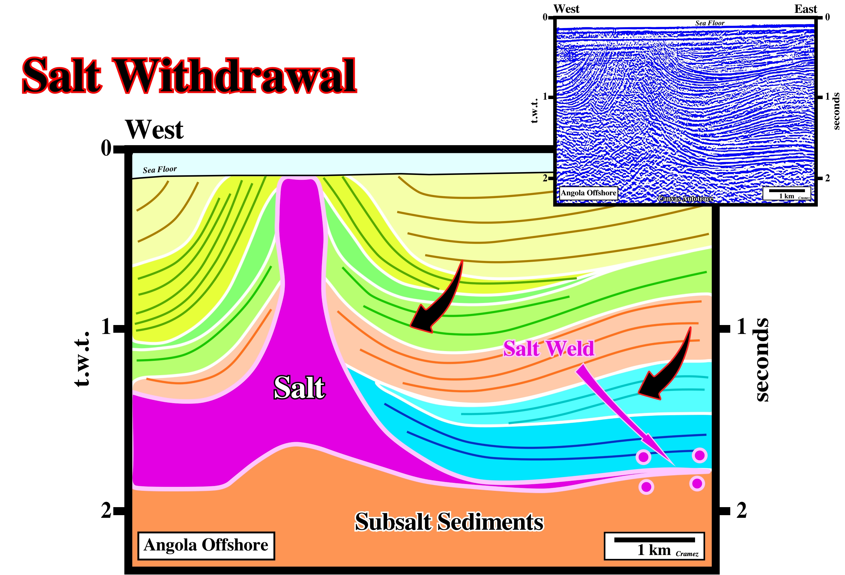
The geometrical relationships between the overburden reflectors and the top of the salt, as well as the thickness changes are, mainly, induced by salt withdrawal that creates a significant differential compensatory subsidence. The geometry, and the internal configuration, of the light green seismic interval (outcropping just above the salt structure) indicates the salt diapir was reactivated not longtime ago.
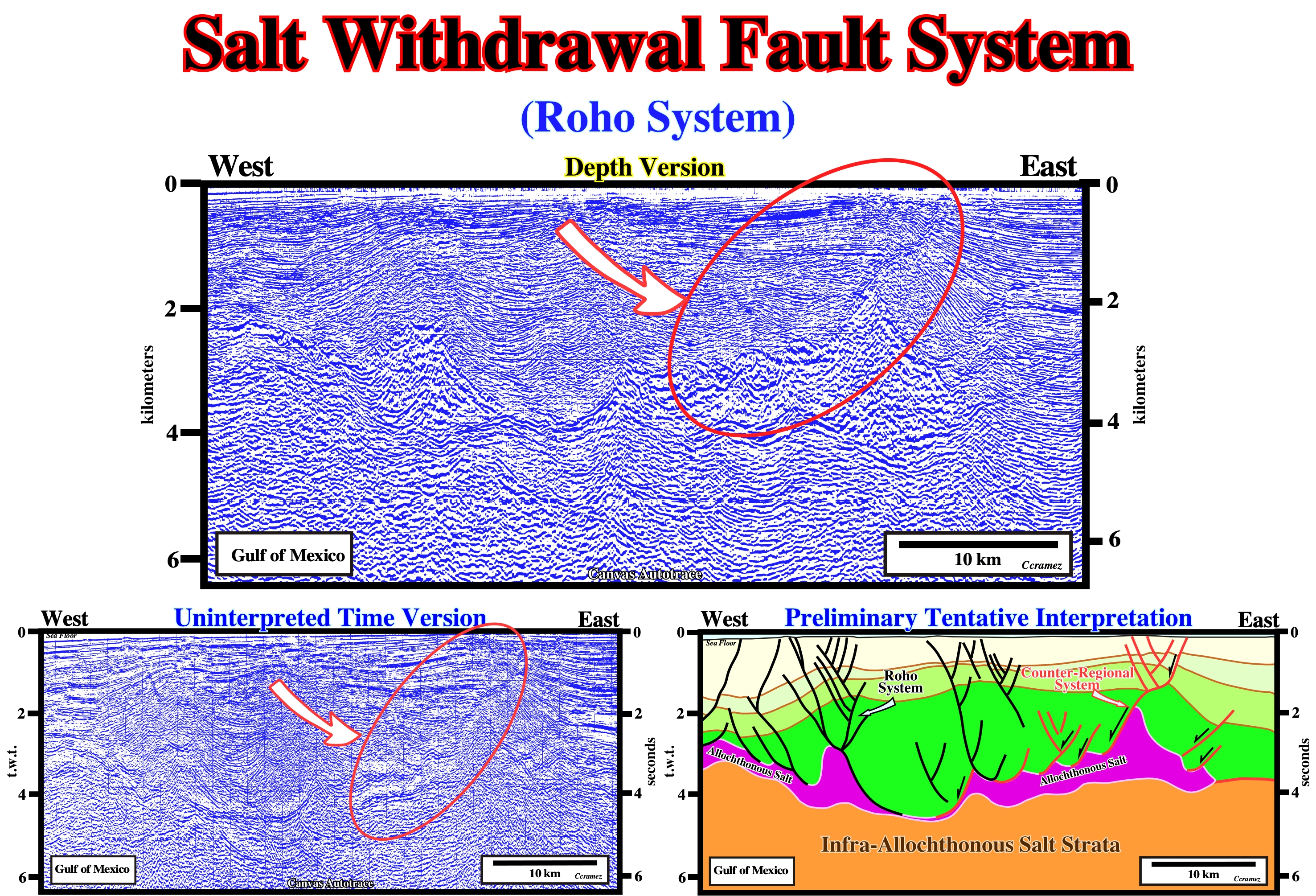
Salt Withdrawal Fault System (Diegel, F. A. et al, 1995)
Synonym of Roho system.
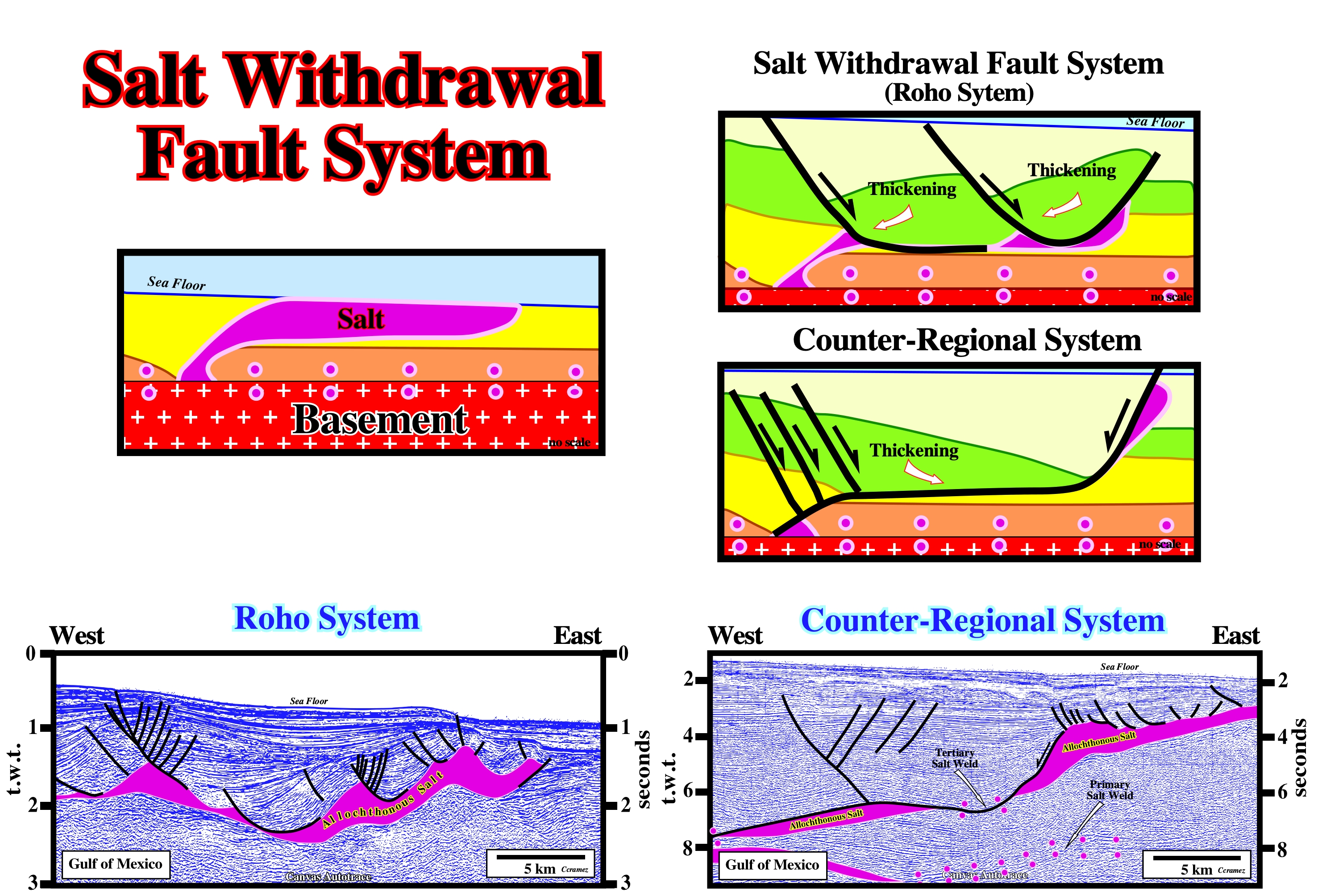
Roho and counter-regional fault systems are associated with allochthonous salt nappes. The faults are, generally, more or less curvilinear growth-faults with the seismic intervals thickening toward the fault plane. The vergence of the Roho faults is seaward, i.e., the fault plane dip seaward and the synkinematic layers thick landward. Contrariwise, the faults of the counter-regional system dip landward and the associated synkinematic layers thick, generally, seaward. In the tentative geological interpretation illustrating the counter-regional system the seaward thickening of the seismic interval of the hangingwall is not evident (is not the direction of the seismic line favourable to show the actual geometrical relationships).
On this preliminary tentative interpretation of a Canvas autotrace of a time version seismic line of the Gulf of Mexico, the thickening of the synkinematic strata of the hangingwall of a counter-regional fault system is evident. That means the compensatory subsidence is induced by a salt withdrawal. The Roho (faults in black) and the counter-regional fault (faults in red) systems are well illustrated on this preliminary tentative interpretation.
Salt Withdrawal Surface (Diegel, F. A. et al, 1995)
Synonym of Salt weld.
A salt withdrawal surface corresponds, often, to a salt weld, i.e., a surface joining rock volumes formerly separated by salt as illustrated on the above Canvas autotrace of a seismic line of South Angola offshore (Benguela geographic basin), which allow recognizing deep, thin and vanished salt. These surfaces when ignored, there is a misinterpretation of the structural history and sequence stratigraphy. When they are combined with extension, they can become complex. A salt welding does not imply relative movement between the overburden and the subsalt strata, but a total salt removal, which could not be the case on seismic data (seismic resolution). Actually, at the seismic standpoint, a salt thickness under seismic resolution is considered a weld and so overestimations of salt reduction are quite frequent.
Sandstone (McNeill, L. et al., 1999)
A medium-grained clastic sedimentary rock composed of abundant rounded or angular fragments of sand size with or without a fine-grained matrix (silt or clay) and more or less firmly united by a cementing material (commonly silica, ironoxide, or calcium carbonate).
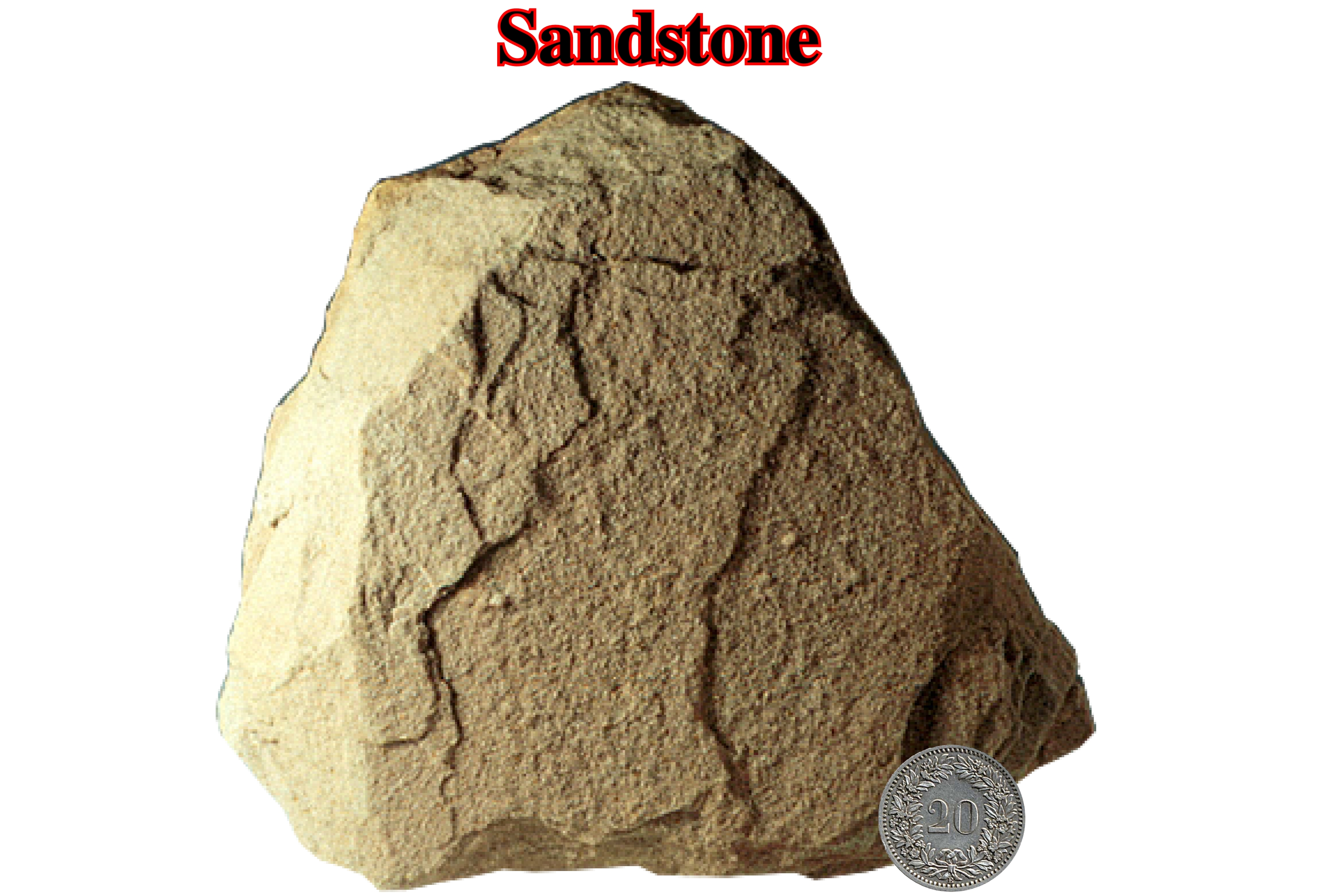
A sandstone is the consolidated equivalent of sand, intermediate in texture between conglomerate and shale. The sand particles are, predominantly, quartz and the term sandstone when used without qualification, indicates a rock containing about 85-90% quartz. The rock varies in color, may be deposited by water or wind and may contain numerous primary features (sedimentary structures and fossils).
SDRs
Term used to express, on seismic lines, the subaerial volcanism emplaced, immediately, after the breakup of the lithosphere of a supercontinent. SDRs are deposit when the spreading centers are subaerial. Synonym of Seaward Dipping Reflectors.
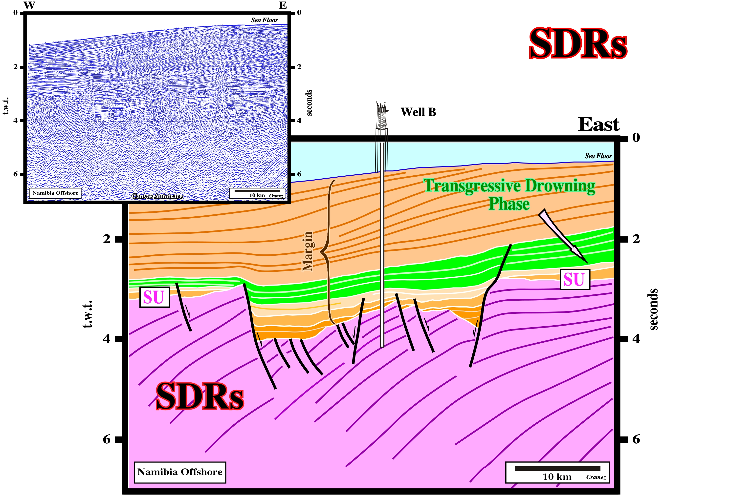
Subaerial volcanism have been found in the South Atlantic margins. The well B found more than 500 meters of lava flows. It is interesting to notice that the dip of the lavas flows increases seaward as new lavas are deposited. This subaerial volcanism was conventional interpreted as hydrocarbon bearing rift-type basin sediments. Unfortunately, the results of the exploration wells refute such an interpretation, and so the hydrocarbon potential of the area, as well.
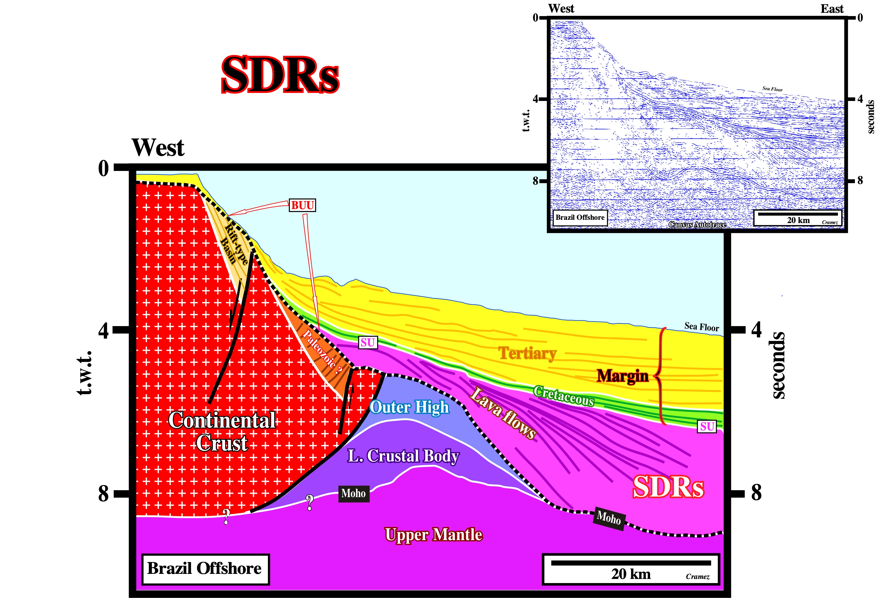
On this tentative interpretation of a Canvas autotrace of a seismic line from Jacuipé geographic basin (Brazil offshore), it is obvious that the subaerial volcanism postdates the breakup of the lithosphere (BUU is the breakup unconformity) and so it cannot be confused with rift-type basin sediments, which, by definition, predate the breakup unconformity. Generally, the rift-type basin sediments dip landward (at time of deposition), while the SDRs dip seaward.
Sea Floor Spreading
A theory that the oceanic crusts is increasing in area by upwelling of magma along the mid-ocean ridges and by a moving-away of the new material at rates of one to ten centimeters per year. This movement provides the source of dynamic thrust in the hypothesis of plate tectonics.
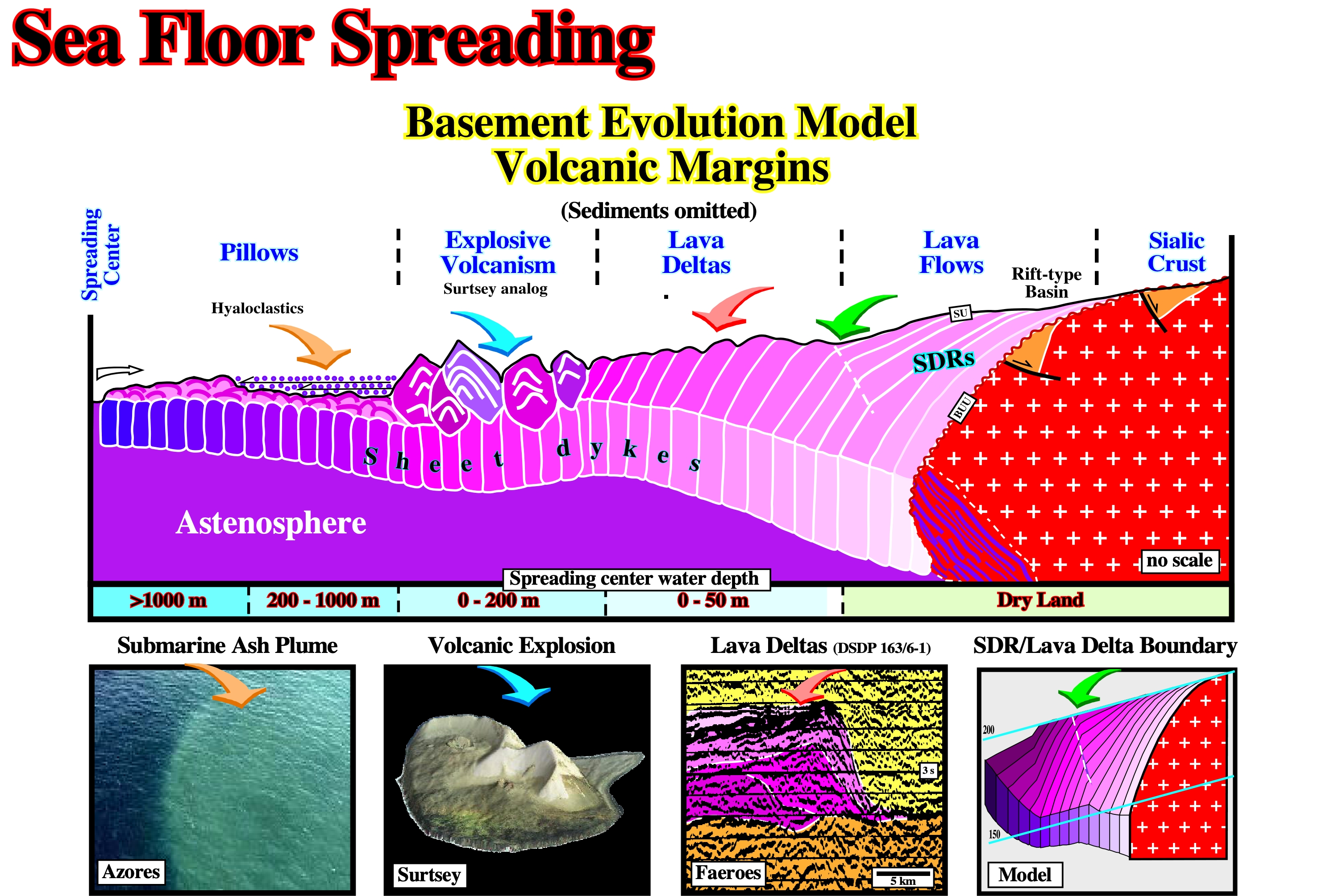
On this geological model proposed by Total SA geoscientists to explain the opening of the Gulf of Mexico, two major phase of oceanic expansion are taken into account: (i) The subaerial expansion with deposition of lava flows and (ii) The oceanic crust, which is, mainly, composed by sheeted dykes. Between the oceanic crust and the lava flows, an area of explosive volcanism and lava deltas can often be recognized.
Second Generation Diapir
Diapirs rising by reactivation of allocthonous Salt.
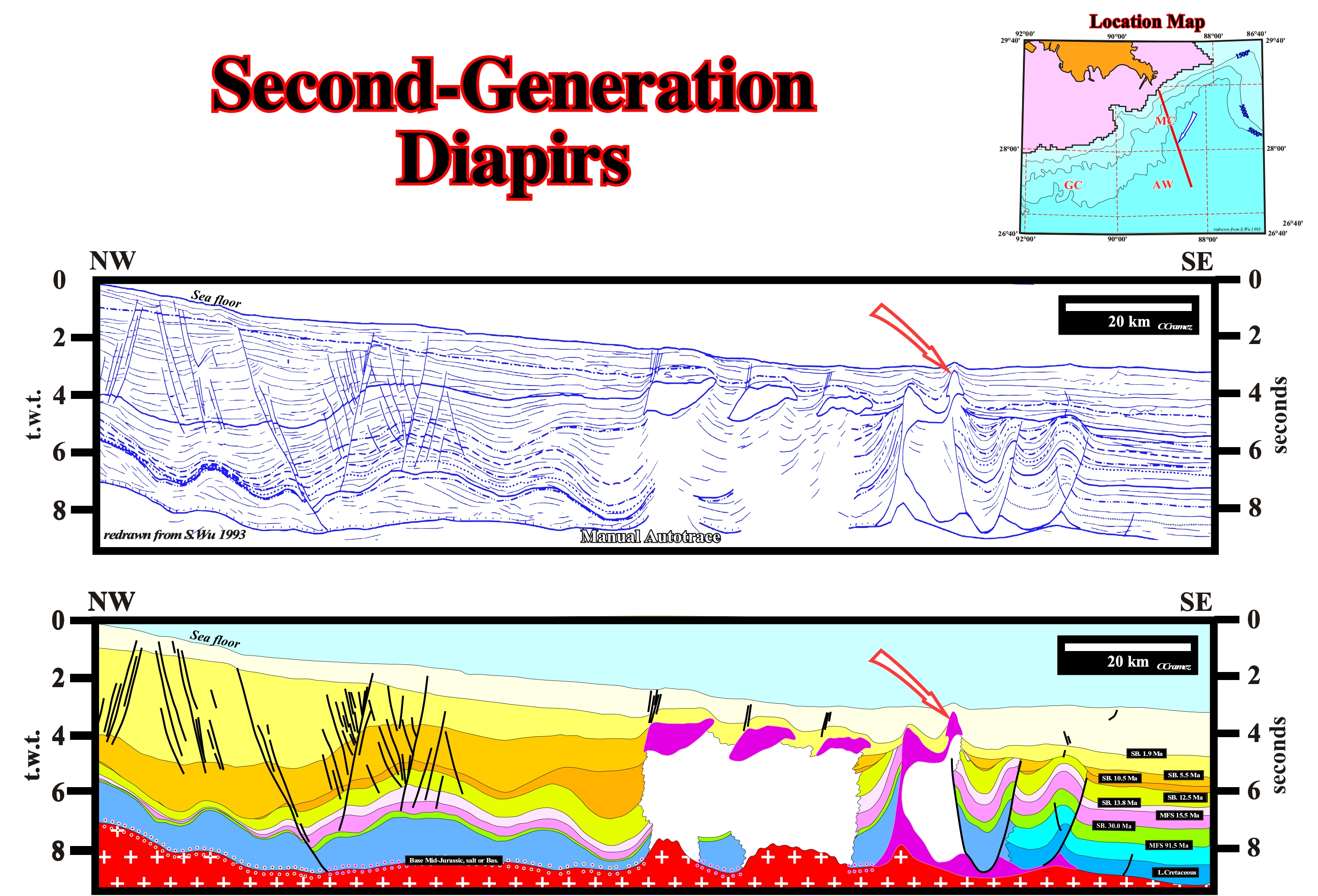
On this manual autotrace of a regional seismic line of the Gulf of Mexico, where the autochthonous and allochthonous salt layers are, easily, recognize, a second order diapir can be recognize in association with an allochthonous salt nappe. It is a typical one. It is located the leading wedge of the salt nappe (see next figure). This tentative interpretation is quite interesting. In the western part of it, not only there is not allochthonous salt, but the autochthonous salt is represented (seismically speaking) just by a long salt weld (more 60 kn). Such a situation allows geoscientists to calculate the regional dip of the bottom of the autochthonous salt, what help quite a lot to determine (roughly) the seismic pitfalls (pull-ups and pull-downs) induced by the lateral thickness variation of the salt layers and/or overburden depocenters.
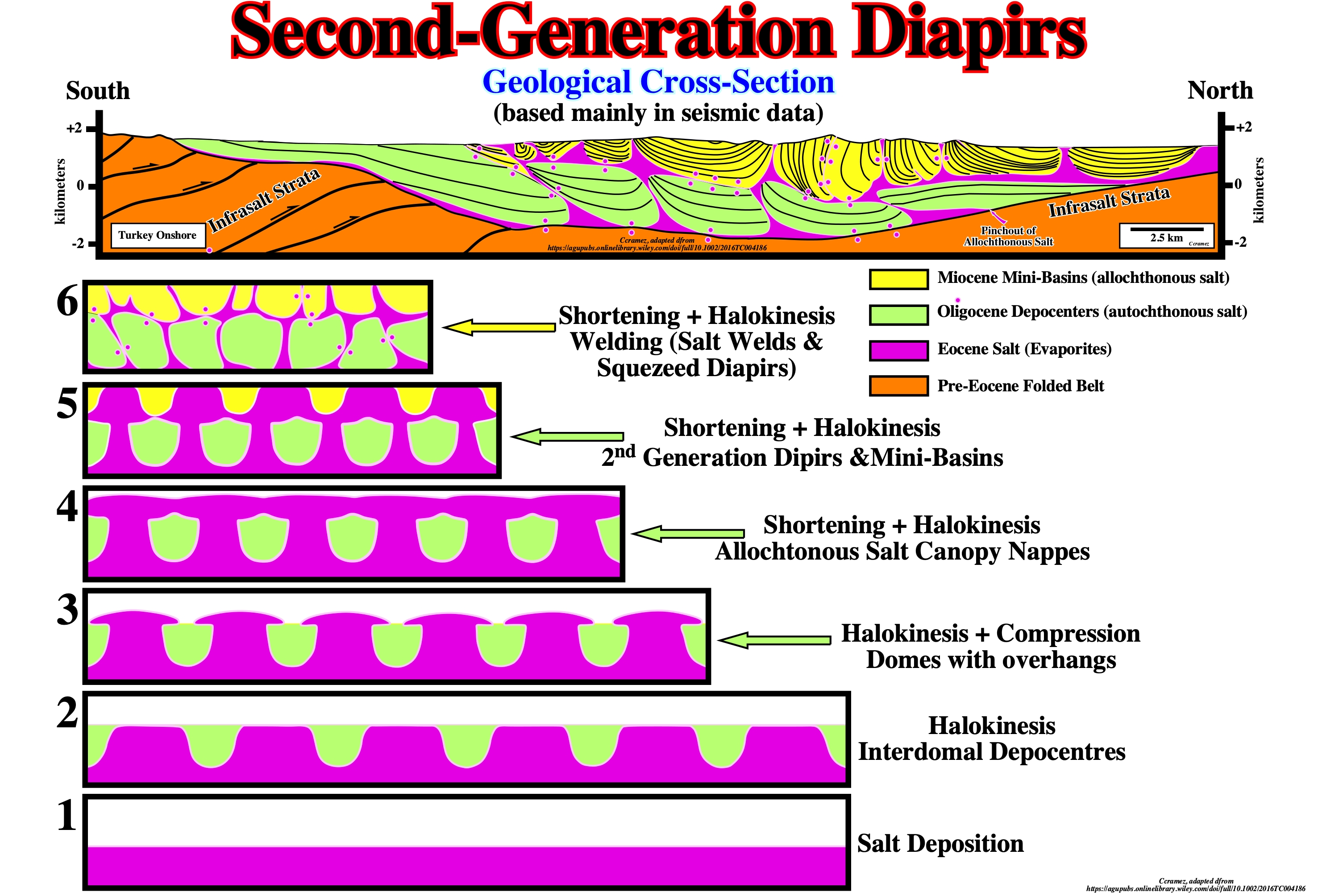
Salt layers (autochthonous or allochthonous) under a compressional tectonic regime can give quite complicated halokinetic structures, as illustrated on the geological cross section of Turkey onshore based on tentative geological interpretations of seismic lines (Kergaravat, C. et al., 2016), illustrated above, in which interdomal depocenters (autochthonous salt), mini-basin (allochthonous salt), second generation diapirs, squeezed diapirs, primary, secondary and tertiary salt welds, etc., are developed. The proposed likely, but not certain salt tectonic evolution (halokinesis plus shortening) helps a lot to recognize certain deformed salt structures. The pinchout of the allochthonous salt is, largely, more proximal than the pinchout of the allochthonous salt, at least in the northern border of the basin (Sivas geographic basin).
Second-Generation Salt Sheet
Salt sheet rising from allochthonous salt.
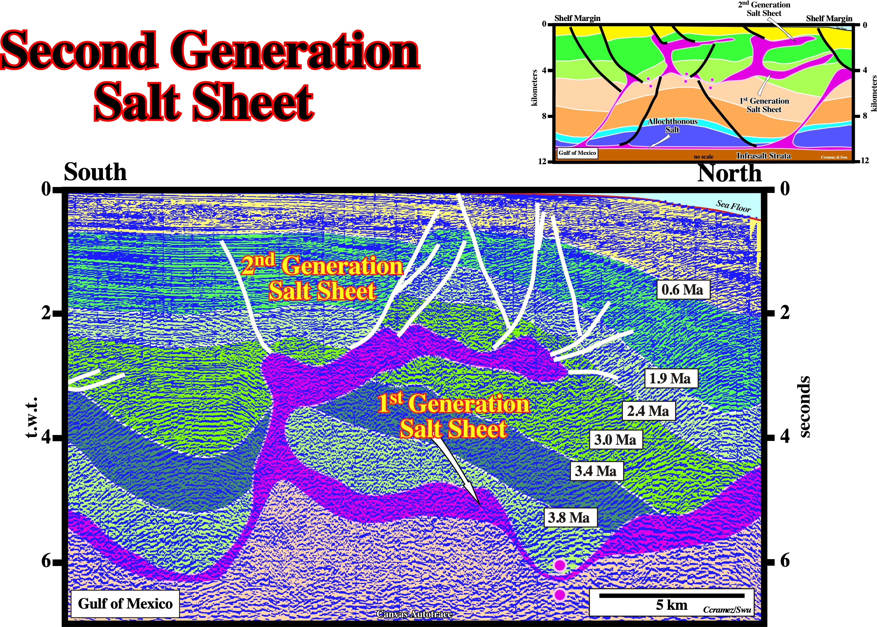
On this detail of a Canvas autotrace of Gulf of Mexico seismic line, two generation of salt sheets are quite evidence. On the first generation salt sheet a tertiary salt weld is quite likely. The tentative interpretation illustrated on the upper right corner of this figure gives an idea of the regional context of the are from which the detail was taken.
Second-Order Cell
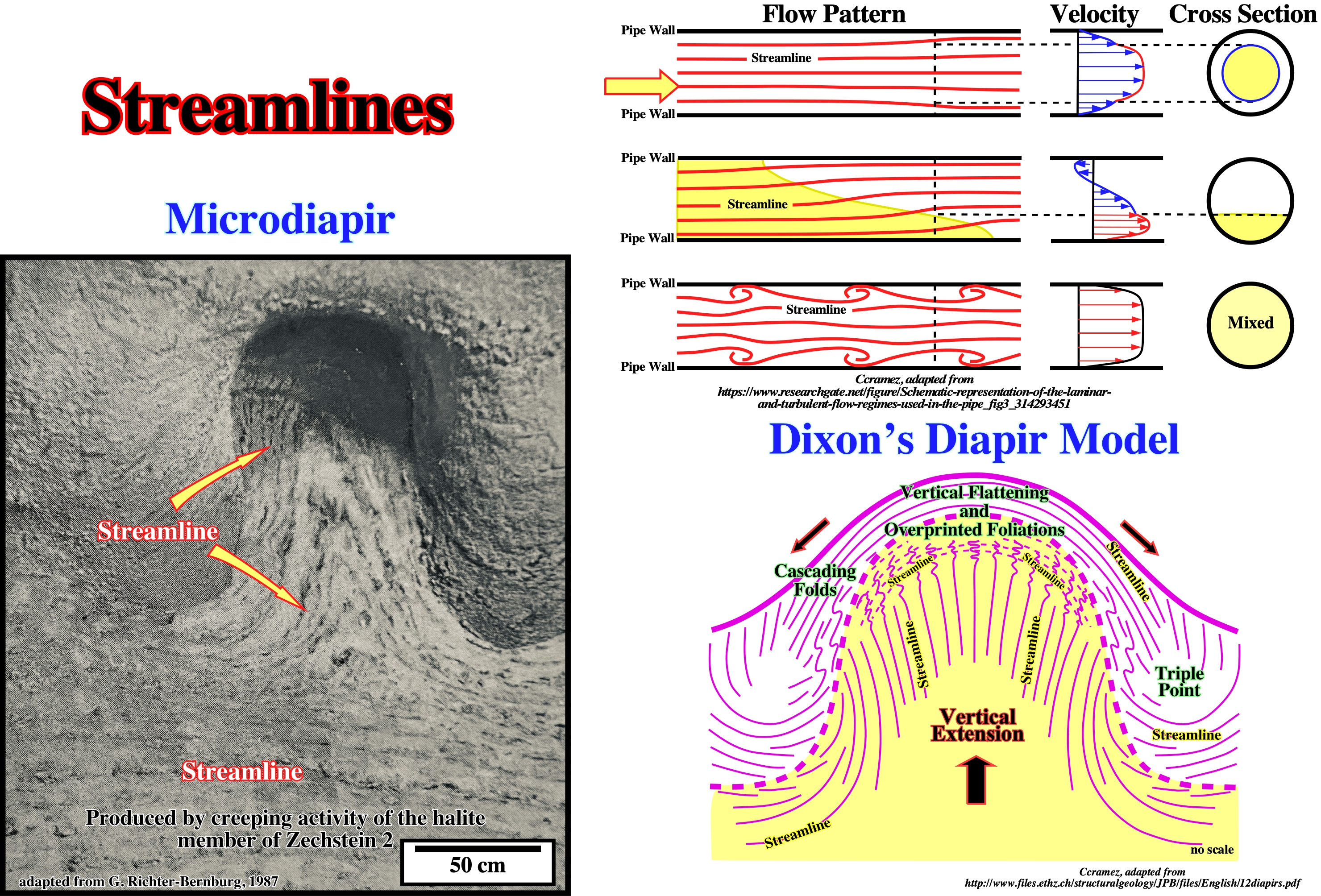
Cell on the scale of a single diapir. The center of the cell is the diapir in which the streamlines rise, whereas its lateral margins are defined by the outer limits of the sinking streamlines.
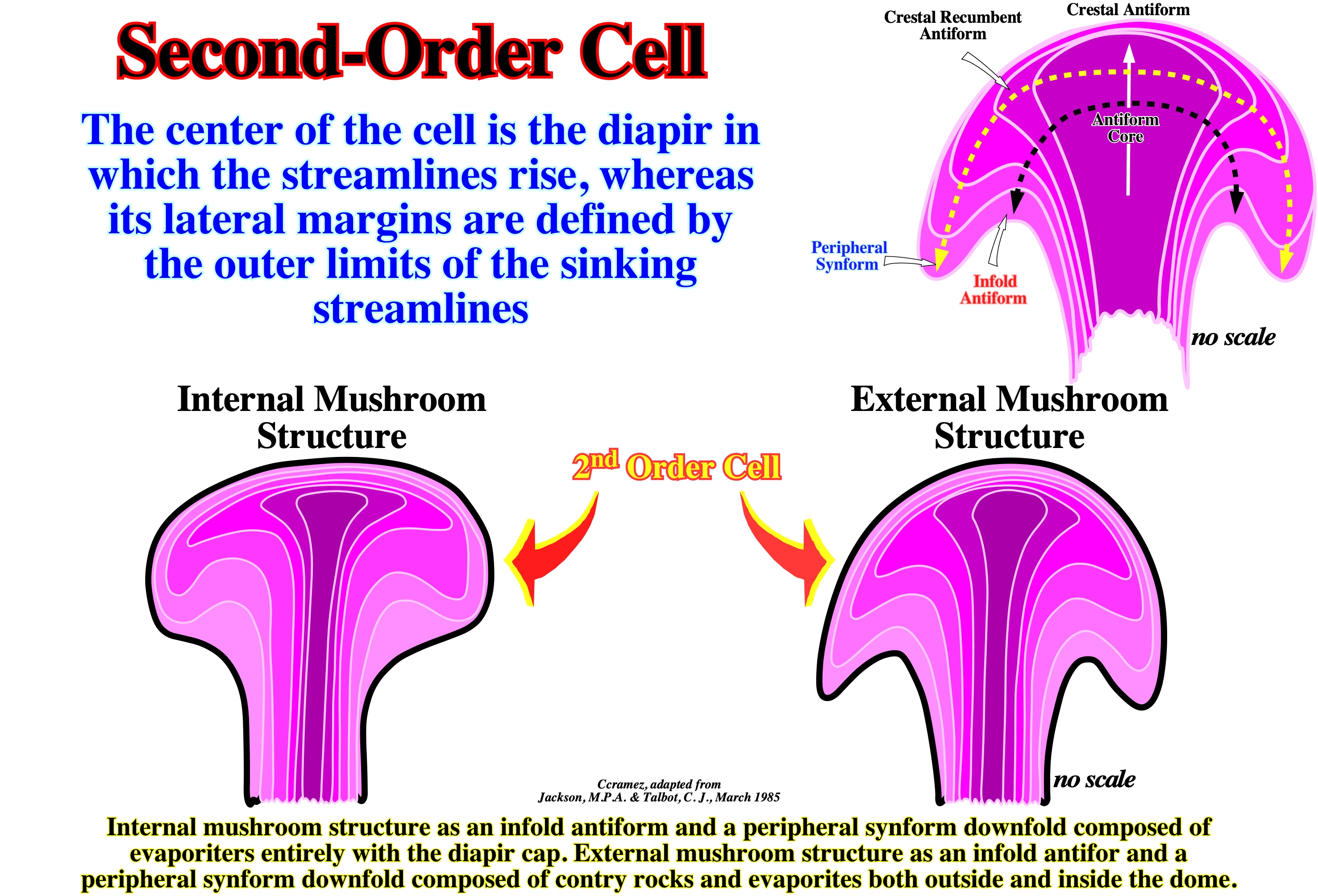
On this figure are summarized the main aspects of a second order salt cell in a single diapir. The center of the cell is the diapir and its lateral margins correspond to the outer limits of the sinking stream lines.
Secondary Peripheral Sink
Peripheral sink, which accumulates around a diapir withdrawing salt from its precursor pillow and contains strata that thicken toward the salt diapir.
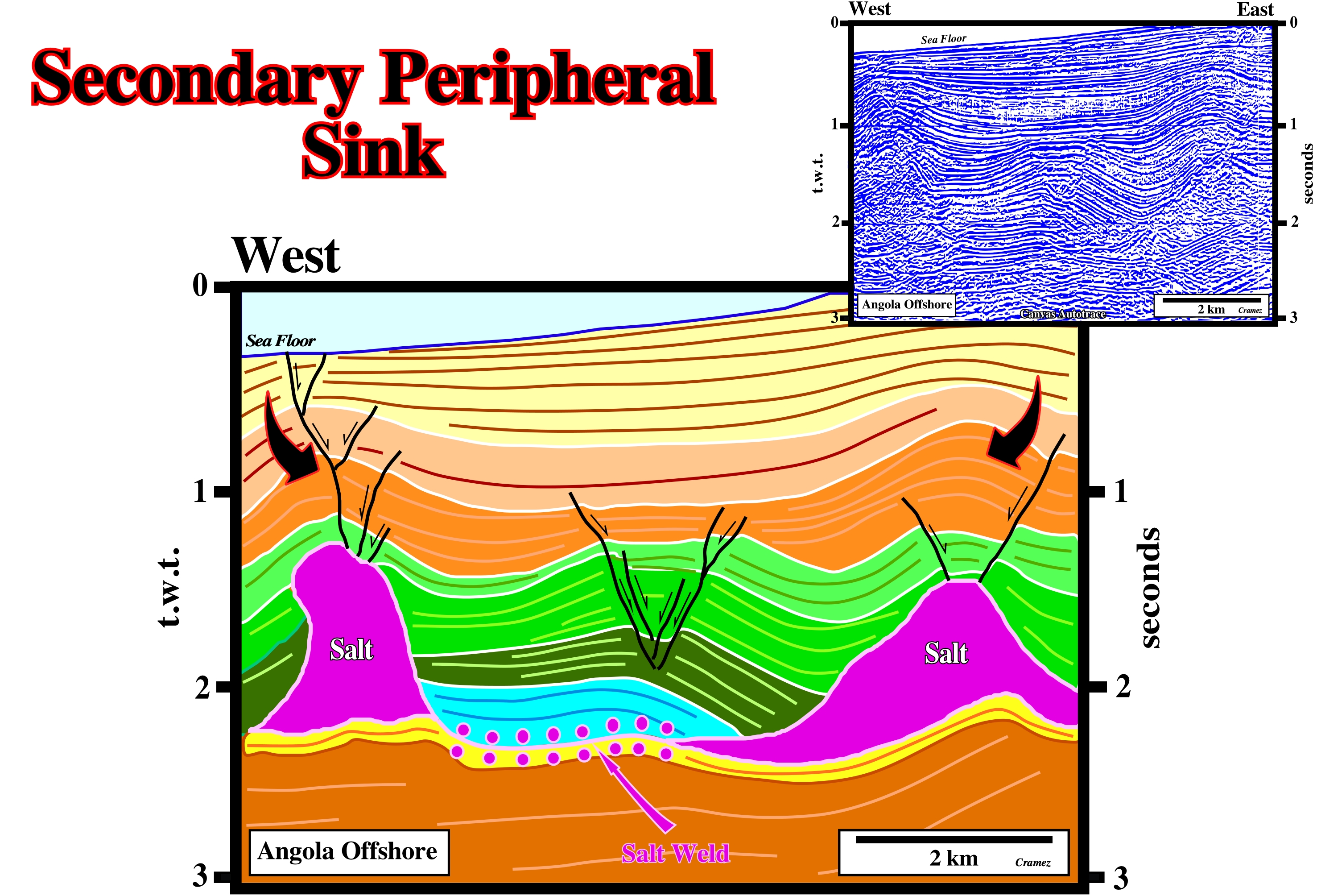
Secondary peripheral sinks are often associated with tectonic inversions whether due to a reactivation of the diapir or late regional compression.
Secondary Salt Weld
Salt weld joining strata originally separated by steep-sided salt diapirs (salt walls or salt stocks).
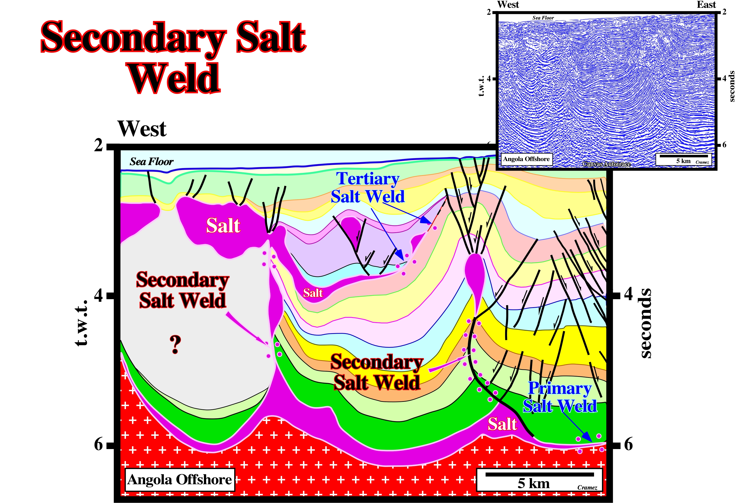
Secondary salt welds have often a vertical geometry, or undated when late regional compressions take place. A primary and a tertiary salt welds are also easily recognized.
Sedimentary Rocks
Rocks resulting from the consolidation of loose sediment that has accumulated in layers.
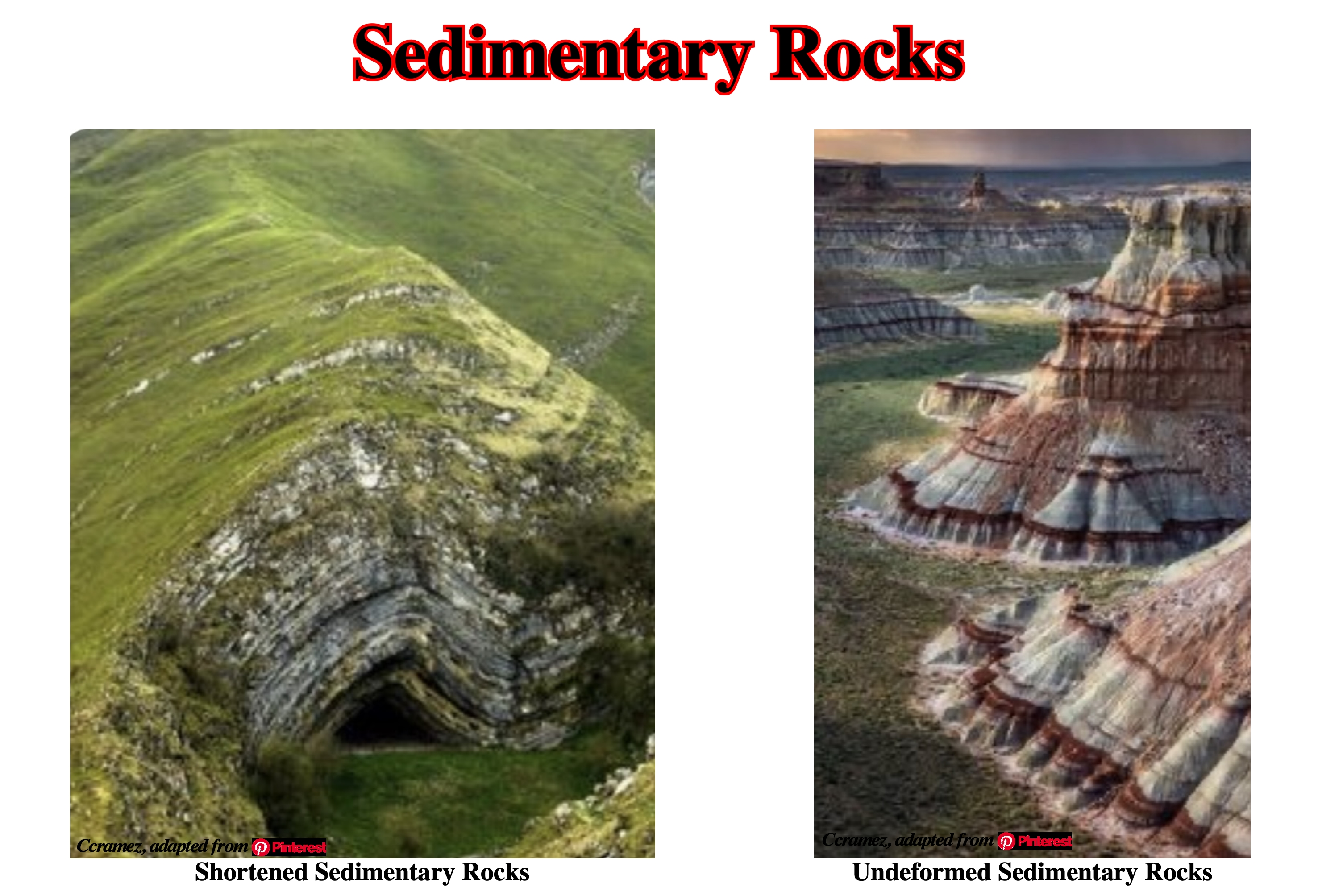
Sedimentary rocks are clastic rocks (such as conglomerates or tillites) consisting of mechanically formed fragments of older rock transported from its source and deposited in water or from air or ice. They can also be formed by precipitation from solution (rock salt). Sedimentary rocks can also consist of remains or secretions of plants and animals.
Sedimentation (McNeill, L. et al., 1999)
The act or process of forming or accumulating sediment in layers, including such processes as the separation of rock particles from the material from which sediment is derived, the transportation of these particles to the site of deposition, the actual deposition or setting of the particles, the chemical and other (diagenetic) changes occurring in the sediment and the ultimate consolidation of the sediments into solid rock. In marine environments deposition takes place when the space available for sediments increases. However, turbidite deposition takes place during relative sea level falls, i.e, when accommodation decreases. Indeed, seaward of the shelf break, the water depth is so big than there is always space available for sedimentation, even during important relative sea level falls.
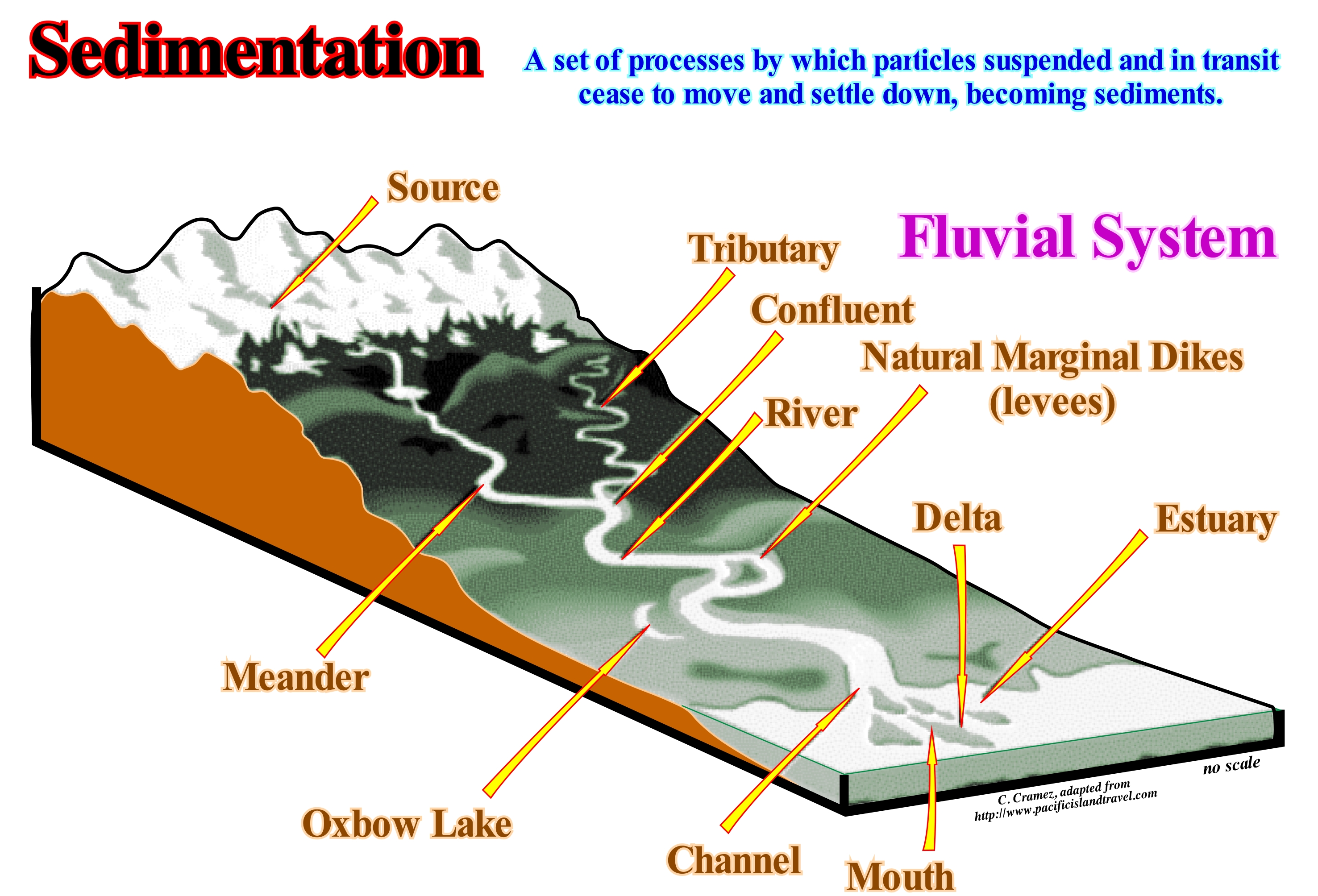
A sedimentary particle is a particle of matter that can be carried by a fluid flow and which is, eventually, deposited in the base of a body of water or other fluid, becoming a sediments. Sedimentation is the deposition by gravity of a suspended material. Sedimentary particles are carried by wind, water and ice. Sand dunes in a desert and loess are examples of wind transport and deposition. The moraines and till are deposits resulting of the deposition of sedimentary particles transported by ice. Point bars and deltas are examples of deposits of sedimentary particles transported by water, as suggested in the scheme shown in this figure. Gravity collapses can create slope and slumping deposits, just as karst collapses create carbonate mounds. Each type of sedimentary particle has different depositional velocities depending on size, volume, density and shape. Over time, the sedimentary particles accumulate in the seas, oceans or lakes, which means that the sedimentary deposits can be terrestrial (deposited in onshore) or marine (deposited in offshore). All siliciclastic sedimentary particles are terrestrial (originating onshore), but can be deposited in terrestrial, marine or lake environments. The deposited sedimentary particles are the main source of the sedimentary rocks, which may contain fossils of the populations inhabiting the water-body, which, after death, fall into the sea bottom and are then covered by more recent sediments. Lake bottom sediments, which have not yet turned into solid rocks, by compaction and diagenesis, can be used to determine the climatic conditions at the time of deposition. For a fluid to begin to transport sedimentary particles, it is necessary that the energy of the flow is superior to energy absorbed by friction. The way sedimentary particles are transported depends on the particles and fluid characteristics. If a fluid, such as water, flows, it can carry suspended particles. The sedimentation velocity (ω) is the minimum velocity that a flow must have to transport and not to deposit the sediments, which is given by Stokes' law: ω =2(ρs-ρf)gr2/9μ, where "ρ" is the density, "g" acceleration, "r" is the radius of the particles, "μ" the dynamic viscosity of the fluid, "s" for particle and "f" for fluid.
Sedimentation Rate
The amount of sediments accumulated in an aquatic environment over a given period of time, usually expressed as thickness of accumulation per unit time. Attention must be done to the completeness and preservation of the stratigraphic intervals.
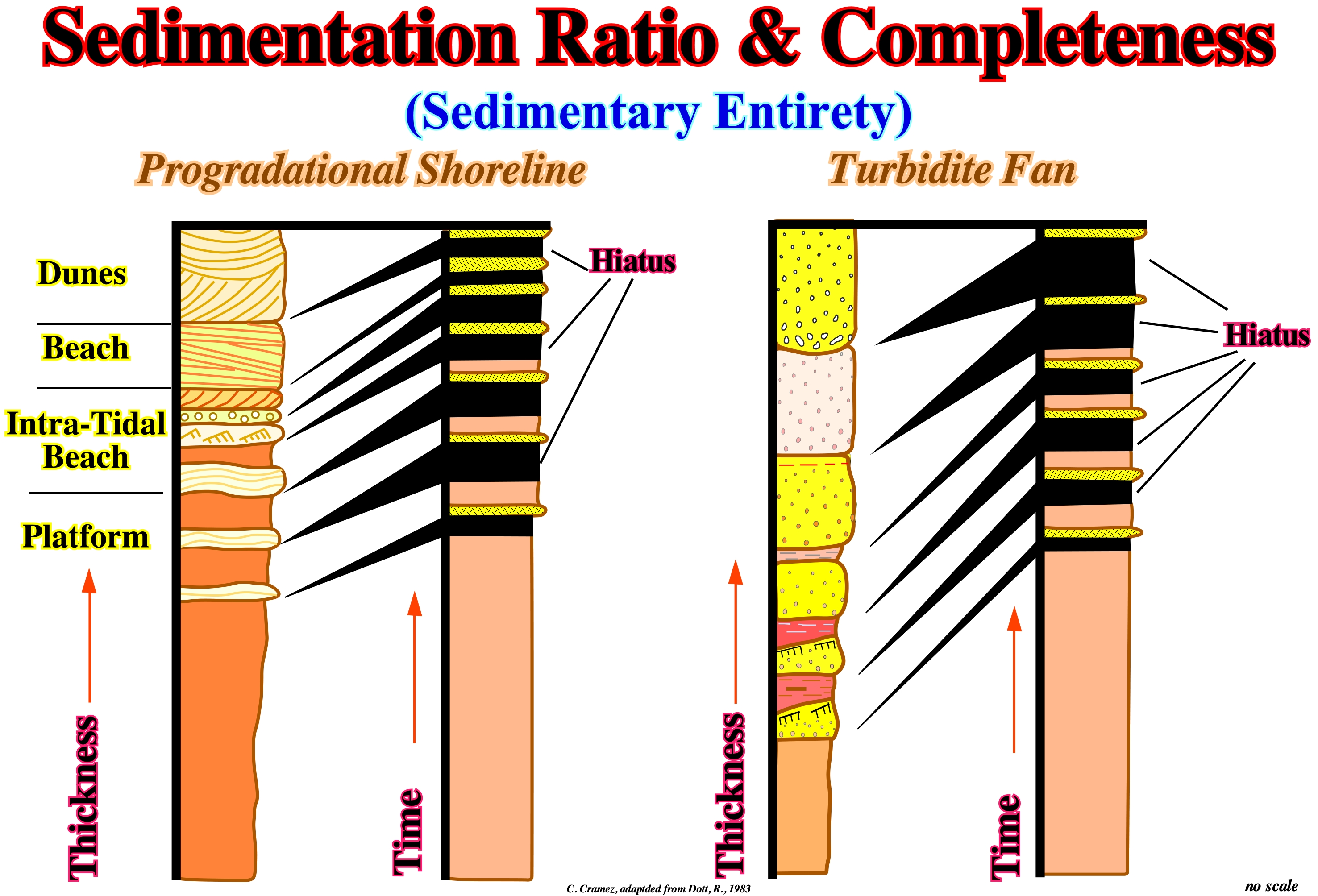
The completeness is the elation between the effective time of deposition and total geological time. If the time between two consecutive unconformities is, for instance, 3.0 My and the effective deposition time is 1.0 My, the sedimentary completeness is 0.3. In turbidite systems, the completeness is small, but the preservation is great. The deposition time of a deep turbiditic lobe (basin floor fan or slope fan) is practically instantaneous (in geological terms), while the time span between two consecutive lobes, during which, practically, nothing happen (from the point of view of deposition), can be thousands of years or more. The knowledge of completeness is essential to determine the sedimentation rate of a given sedimentary interval. Three questions come, always, to the spirit of geoscientists: (1) How long is a sedimentary layer deposited? ; (2) How long does a given stratigraphic section deposit? and (3) In comparison to the total deposit duration of a stratigraphic section, how long is there, actually, deposition? The answers to the first two questions are relatively easy: a) A beach deposit lamination is deposited in about one second ; b) A layer of HCS ("cross-stratification"), characteristic of storm deposits, is deposited in a few minutes ; c) A turbidite layer is deposited in a few hours ; d) Flood deposits, such as the Scablands (deposits and erosions associated with flooding caused by the behind retention rupture of lakes associated with the Pliocene/Pleistocene glaciers of Canada, are deposited in a few weeks ; e) The glacial varves deposit in 1 year ; f) One centimeter of pelagic sediments deposits in about 103 years ; g) A continental encroachment subcycle deposits in 10/20 x 106 years ; h) A continental encroachment cycle deposits in 100-200 x 106 years. In 1982, on this subject, P. M. Sadler showed that the duration of a deposit is inversely proportional to the sedimentation rate, i.e., higher is the sedimentation rate, shorter the deposition period. From this, it can be deduced that most periods of no deposit escapes us, which led Ager to consider that sedimentary records correspond to short periods of terror separated by long periods of calm, where nothing happens. As all geoscientists know, in all stratigraphic systems, whether they are Silurian or Cretaceous, deposits are episodic, incomplete, and with numerous erosion and non-depositional hiatus. The deposits do not translate in any way the equivalent duration of geological time. In the stratigraphic sections, whether they are deep-water or not. The time of no deposition and erosion is almost always greater than the actual deposition time of the preserved sediments. As illustrated in this figure, this is particularly true in turbidite deposits and coastal deposits. In the upper part of this figure, in the stratigraphic models (progradational shoreline, i.e., during sedimentary regressions and turbidite depositional systems) it is important to note in the upper part of each section the duration of the periods of non-deposit is largely higher to the periods of deposition. Most of the geological events that occurred during these periods were not preserved. The completeness of a deposit is given by the ratio of the deposition time to the total time (depositional time plus hiatus). Turbidite deposits and, in particular, submarine basin floor fans have a very small completeness. The deposition time of each turbidite layer is, geologically, instantaneous, but the time between two consecutive turbidite currents, during which the pelagic shales are deposited, is very large, sometimes more than 1 My. If in a submarine basin floor fan, composed of 100 turbidite layers and pelagic shales in which each turbidite layer has a thickness of 20 cm and each pelagic layer has a thickness of 5 cm, the total thickness is of 2,500 cm. As the average deposition rate of pelagic shale is, say, 5 cm / 1,000 years and the turbiditic currents are instantaneous stratigraphic events, it can be deduced: a) Total deposition time was 100,000 years and b) The frequency of turbiditic currents is 1,000 years, which means that two-thirds of the sedimentary interval has been deposited by instantaneous events, the frequency of which is one event every 1,000 years. On the other hand, it is important not to forget most of the sediments associated with the different geological events occurring during the deposition periods are not preserved. In fact, the preservation of the stratigraphic sections is related to: (i) Amplitude; (ii) Frequency of stratigraphic events and (iii) Depositional environment. The stratigraphic events most represented in the stratigraphic records are those that have normal or low frequency,i.e., those that occur sporadically. In terms of frequency. As said above within a sequence cycle, the basin and submarine slope fans are very significant since the turbidite levels contrast sharply with pelagic intervals between them. Pelagic stratigraphic intervals are events of normal frequency, whereas turbidite intervals are associated with events, geologically, instantaneous.
Sedimentation Surface
Synonym of Bedding plane.
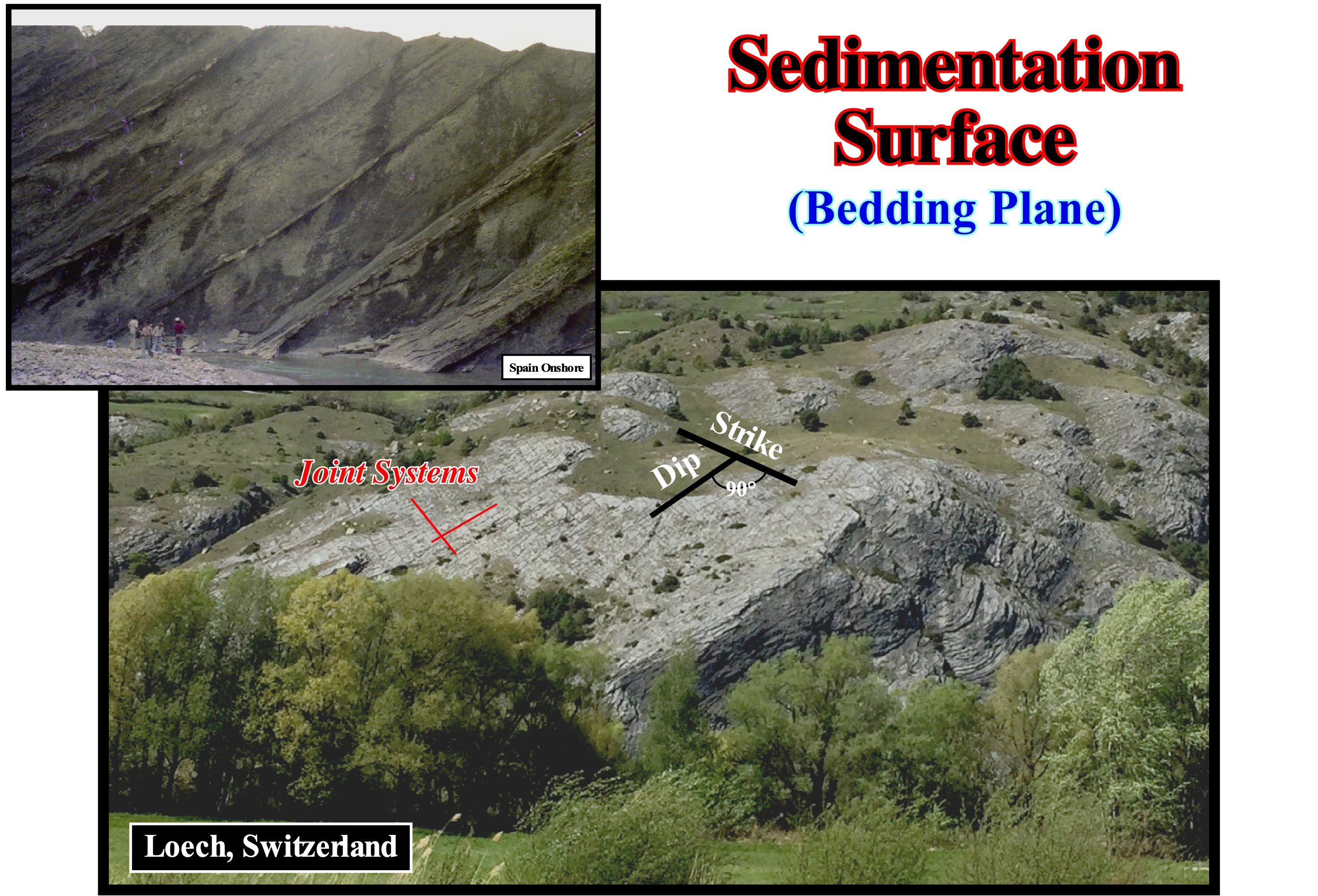
As shown in this photograph, sedimentary beds are bounded above and below by surface or bedding planes, which are, generally, the easiest elements to identify in an outcrop. They are used to subdivide the rocks into beds and to determine the order and relative time of accumulation of the sediments that form them. The characteristics of the bedding surfaces or planes, whether they are, more or less, eroded, cemented, perforated, or bioturbated, are used in the interpretation of sedimentary rocks. Some geoscientists, based, mainly, on observations made in fluvial sediments, consider that four major types of bedding surfaces can be considered: (i) Concordant, that is, without significant erosion (normal stratification) ; (ii) Nonconcordant but without significant erosion ; (iii) Concordant with Erosion and (iv) Nonconcordant with Erosion. Recall a discontinuity can designate a transition or contact between: a) Different sedimentary facies (lithologies) ; b) Intervals separated by a hiatus (absence of significant deposition) ; c) Intervals with different densities, etc., and they consider: 1-Stratigraphic Discontinuities ; 2-Sedimentary Discontinuities; 3 -Lithological Discontinuities ; 4-Tectonic Discontinuities, etc. A bedding surface is a stratigraphic discontinuity. Within this family of discontinuities, which is the most important in sequential stratigraphy, several types can be recognized: (i) Concordants, when there is continuity between the successive intervals ; (ii) Paraconform or Paraconformities, when there is no difference in attitude between overlapping intervals, but there is a hiatus due to the absence of significant deposition between them ; (iii) Nonconformities (heterolytic discontinuities of certain geoscientists), when there is a contact between a sedimentary interval and an older igneous body ; (iv) Disconform or Disconformity, when the layers of the intervals are parallel on one side and the other side of the contact surface which does not conform to regional stratification ; (v) Discordant Discontinuity or Unconformities when the two interval are separated by an erosional surface induced by a relative sea level fall ; (vi) Tectonically Enhanced Unconformities, when the sediments of the interval overlapping an unconformity were deformed by tectonics (shortened or lengthened) ; (vii) Intrusive Discontinuities, when an igneous body traverses a sedimentary series ; (viii) Mechanics, when they are induced by faults, etc. (https: // estpal13. wordpress.com / 2013/06/04 / discontinuities-sedimentary-and-stratigraphic /). The origin of the bedding planes remains puzzling. Certain geoscientists think that many bedding planes are, probably, formed by the erosion of sediment not, or little, consolidated on the surface of the deposit. The weight of the sediments, immediately below the surface, causes the sediments to lose water and compact a little, which makes them more cohesive. If the surface of the sediments is subject to an erosive agent (storm waves, tidal currents, river currents, turbidite flow, etc.), the bedding surface erodes a part of the sediments, truncating the less cohesive ones and exhuming the more firm lower sediments. When deposition resumes, it is on the firmer surface that the new sediments will deposit. It can be said that the difference in density between uncompacted sediments (with lots of water) and slightly compacted sediments (with less water) can create a bedding plane. If the deposition takes a while to resume the bedding plane is, in general, perforated by Glossifungites (ichnofacies representing a set of holes). Obviously, the bedding planes are chronostratigraphic surfaces. On the seismic lines, it is evident that bedding plans can not be evident (the seismic resolution is seldom less than 30/40 m), which means that the seismic reflectors do not correspond to bedding surfaces. However, groups of layers with similar lithological and physical characteristics can form, more or less, homogeneous sedimentary intervals or packages that can define sedimentary interfaces that are, perfectly, visible in the seismic data. The great majority of seismic reflectors are induced by these interfaces that allow a seismostratigraphy, which the scale of the cycles follow, translates and gives, in a, more or less, way the stratigraphy and the geological history of the basin.
Seismic Surfaces
Subtle surfaces defined by reflection terminations. Onlap surfaces and downlap surfaces are examples of seismic surfaces.
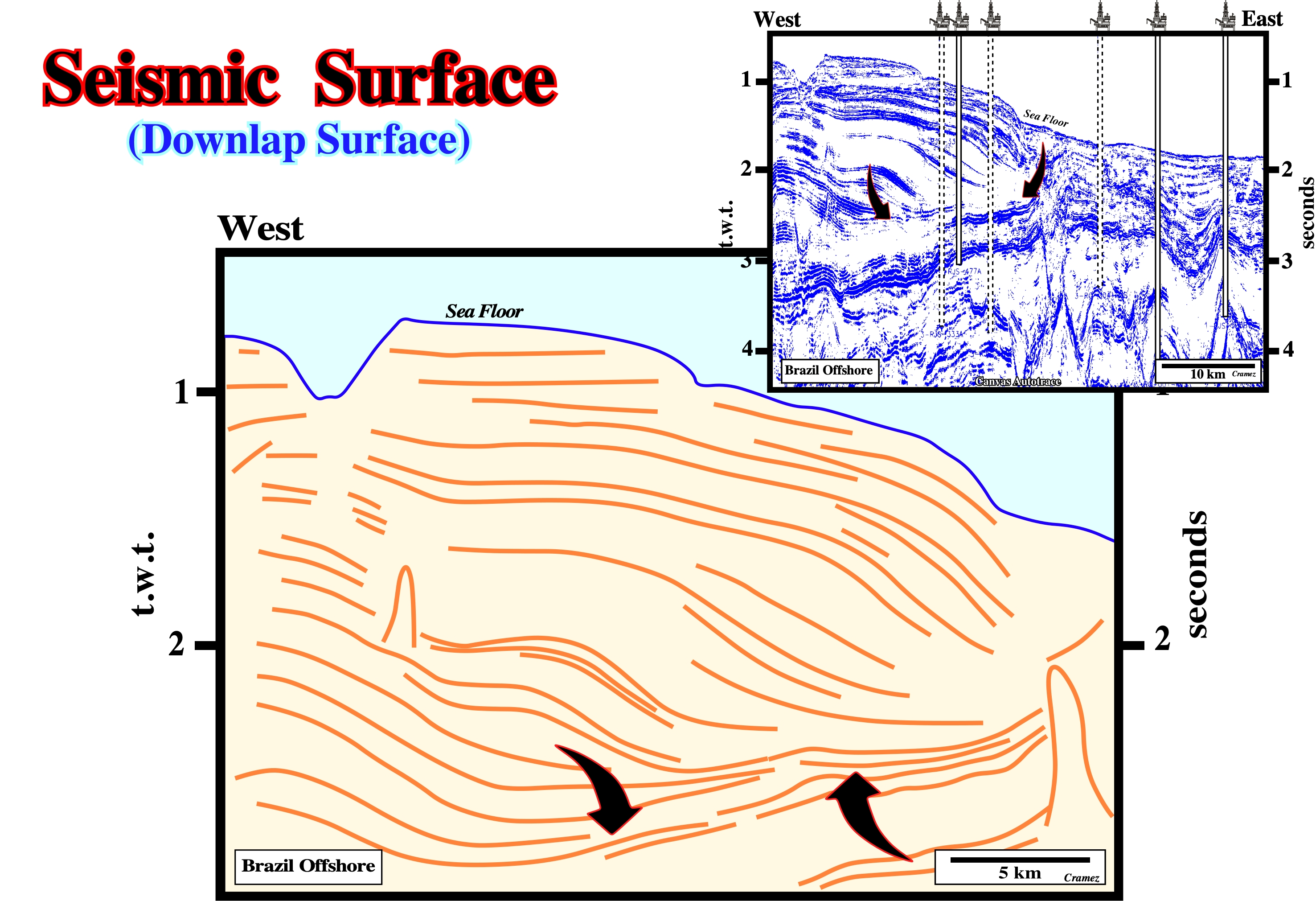
On this tentative interpretation of a Canvas autotrace of a Brazil offshore seismic line, a major seismic downlap surface is obvious at the bottom of the progradations of the uppermost sedimentary package. This surface emphasizes the limit between a transgressive and regressive episode, i.e., between the Middle and Upper Cretaceous sediments.
Shale Tectonics
Term expressing deformation taking place under a combination of shalokineisis with a tectonic regime, whether compressional or extensional.
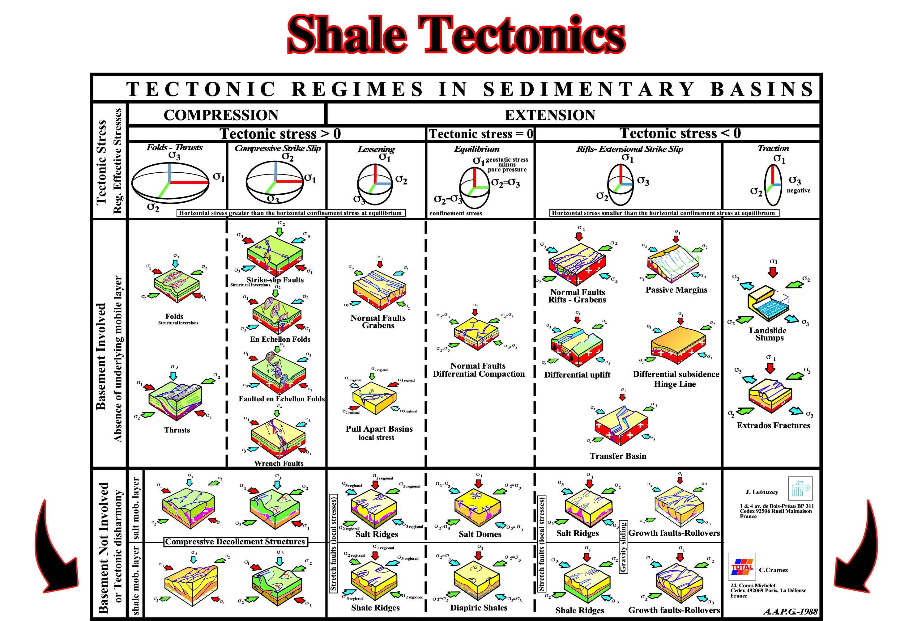
On this plate, which summarizes the main tectonic regimes found in the sedimentary basins, the lower row correspond to what the majority of the geoscientists call shale tectonics, characterized a basement not involved, a shale mobile layer, in which the tectonic stress (σt) can be higher than zero (σt > 0), equal to zero (σt = 0) or lower than zero (σt< 0).
Shalokinesis
Synonym of Argilokinesis.
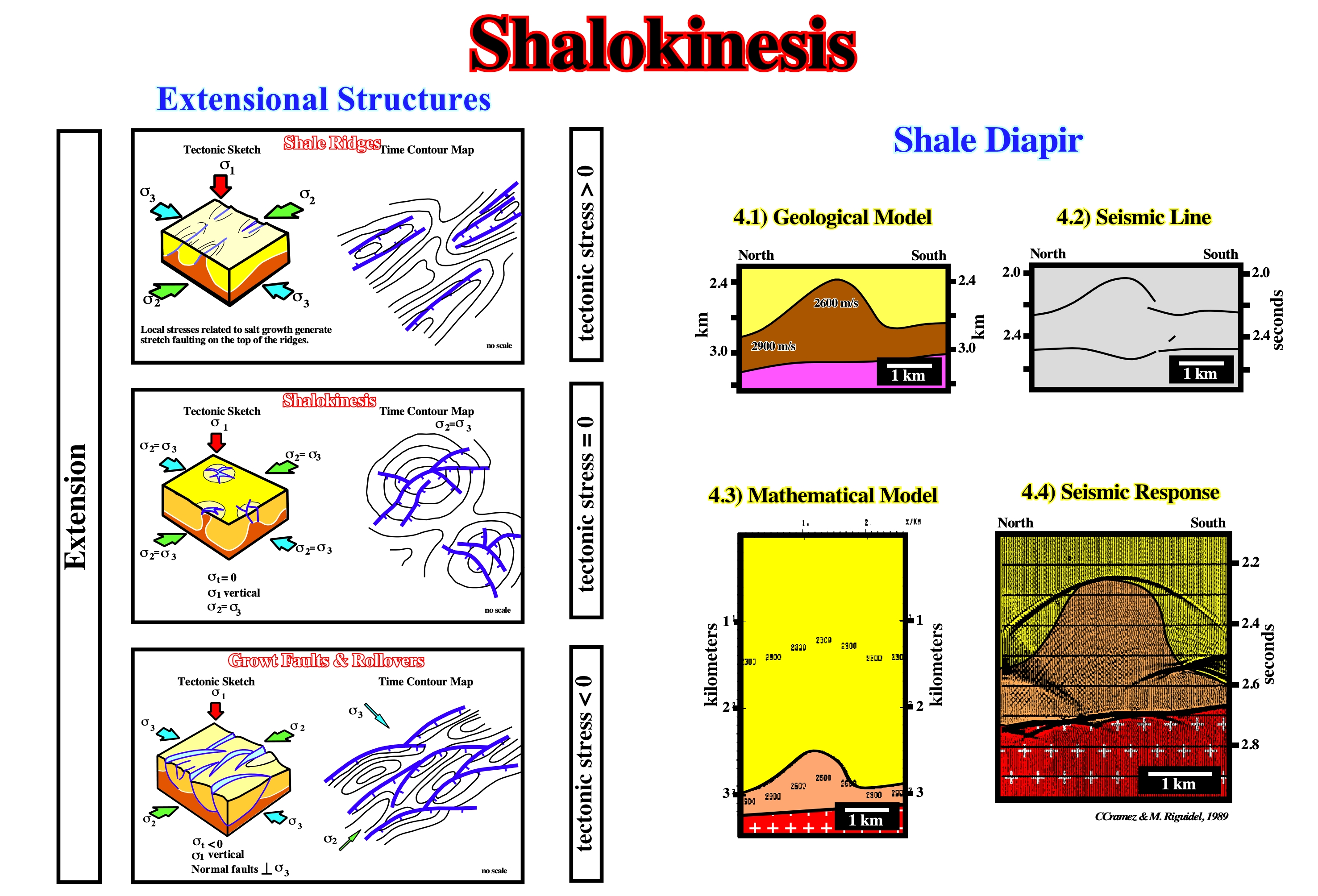
Generally, the bottom of a shaly mobile substratum is difficult to recognize. However, when it can be seen, contrariwise to the bottom of a evaporitic layer, a negative velocity anomaly (pull-down) is present in association with the tectonic disharmony, i.e. the detachment or decollement surface. Lengthening can be associated with a tectonic stress positive (σt >0) with shale ridges developed, partially, parallel to the regional σ3 and local stresses in the apex of the ridges create stretching faults parallel to the ridges. With a negative tectonic stress (σt< 0), the shale movements can produce: (i) shale ridges parallel to regional σ2 , (ii) growth faults, (iii) rollovers, (iv) gravity slidings, etc. With a tectonic stress nil, i.e. in absence of a major tectonic stage, shalokinese can be very important. It usually it is synchronous of sedimentation and it can control, as the halokinesis, the facies and the thickness of the sedimentary sequences. As shalokinesis (σt= 0) is almost always associated with shale ridges, growth faults, rollovers, etc., that is to say when the tectonic stress (σt) is < 0, we prefer, by commodity, to study all the shale movements together. Shale tectonics is the deformation of shale involving no major tectonic stage. Shale tectonics is similar to salt tectonics. In addition, these two types of tectonics are very often together (Gulf Coast ), and it is not always easy to differentiate salt domes from shale domes. On seismic lines, particularly at the bottom of mobile substratum, pull-ups and pull-downs can be difficult to recognize. The chiefly principles of shale tectonics can be summarized as follows: B.1- Plasticity, which is mainly due to undercompaction resulting from: (i) Rate of deposition ; (ii) Burial ; (iii) Thickness ; (iv) Absence of evacuation drainage, etc. ; B.2- Undercompaction, which produces a lowering of the density: a 30-40 % decrease compared with the density of normally compacted shale and a geostatic disequilibrium which results in a vertical and lateral movement of the undercompacted shale.
Shear Zone
Band of highly deformed rock separating two rock masses that have sheared past each other. A brittle shear zone is marked by faults, whereas a ductile shear zone contains a continuous zone of high ductile strain. Three types of shear zone associated with salt diapirs have been recognized: (i) external ; (ii) boundary and (iii) internal.
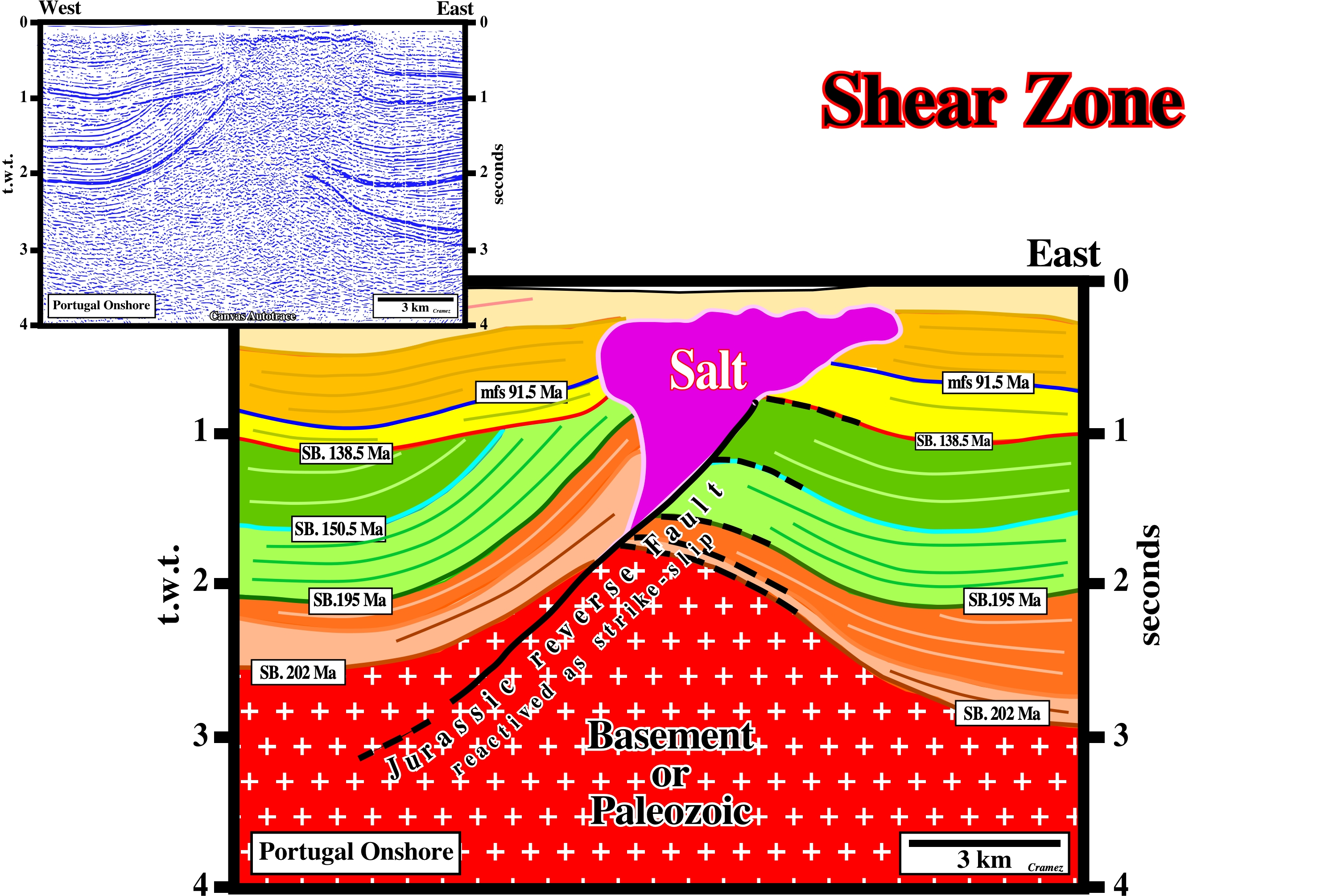
Shear zones and particularly fault zones are often feeders of salt extrusion as illustrated on this tentative interpretation of a Canvas autotrace of a Portugal onshore seismic line (Lusitanian geographic basin). Actually, on this area, some of these faults, more or less, injected by salt, are seismically actives and have been the source of major earthquakes.
Sheath Folds
See: Glacial structures.
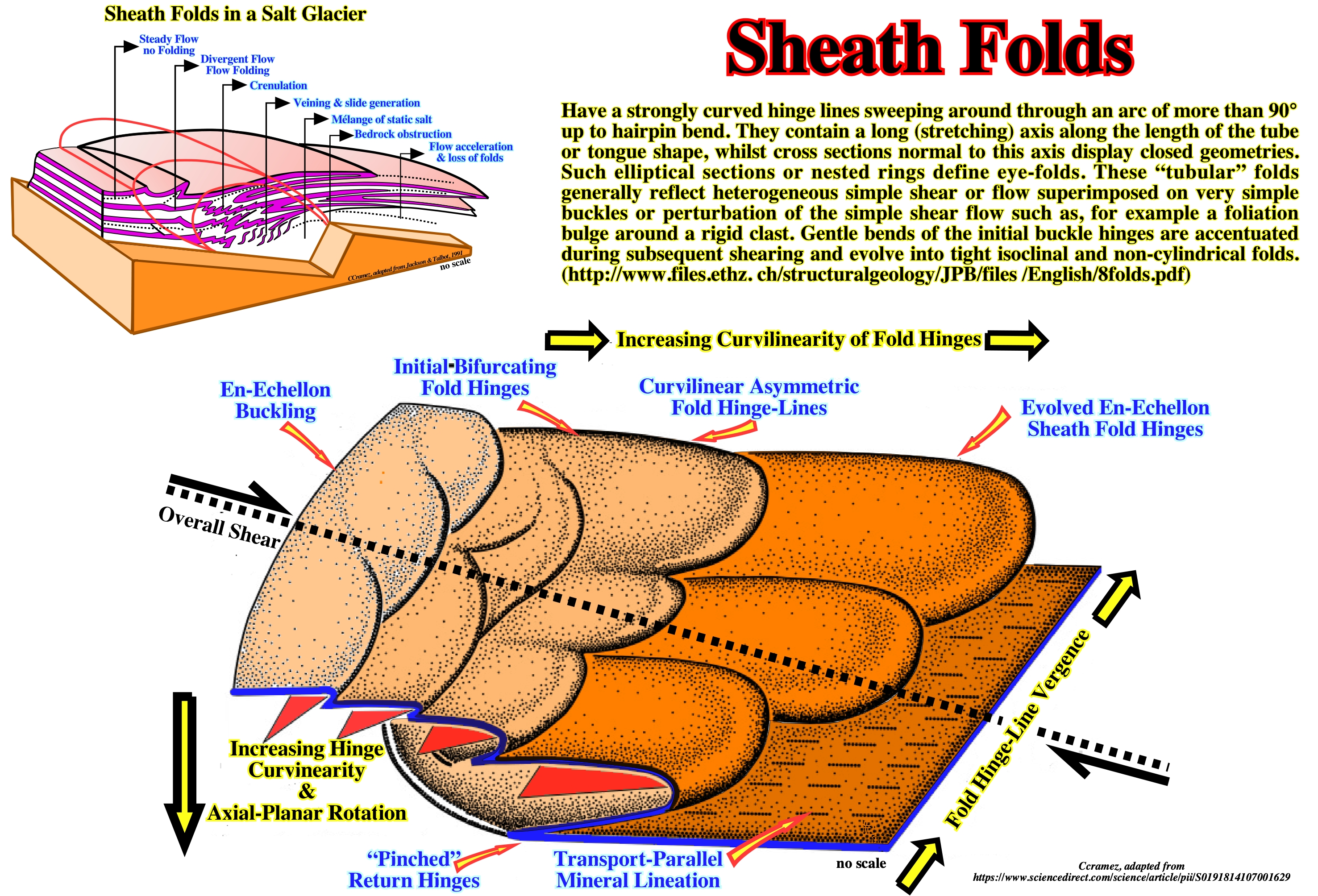
Two parameters are used in the classification of highly non-cylindrical folds: the hinge line angle and the ratio of the length of the cone axis to that of the long axis of the cross-section of the structure at the position where the hinge angle was measured. (https://www.sciencedirect.com/ science/article/pii/0191814189900059). If in a non-cylindrical fold a cross-section can be selected so that the hinge angle measured where the cross-section cuts the cone is less than 90°, and the length of the cone axis x is more than a quarter of the length of the long axis y of the cross-section, the fold is a sheath fold. A tight sheath fold, with w < 20° and x:y > 1, can be termed a tubular fold. A tubular fold is thus an extreme type of sheath fold. While sheath folds with w > 20° but < 90° and x:y > 0.25 but < 1 can be developed by superimposition of layer-parallel simple shear on almost any initial non-cylindrical irregularity, recognizable tubular folds can only be developed from initial non-cylindrical progenitors whose long axes are parallel or almost parallel to the later shearing direction. Such progenitors of tubular folds can be formed by local shortening subperpendicular to the later shearing direction, or they can form in ductile strike-slip zones subparallel to the shearing direction of the later layer-parallel simple shear.
Sheet Inflation
Vertical thickening of a laterally injected salt laccolith or sill.
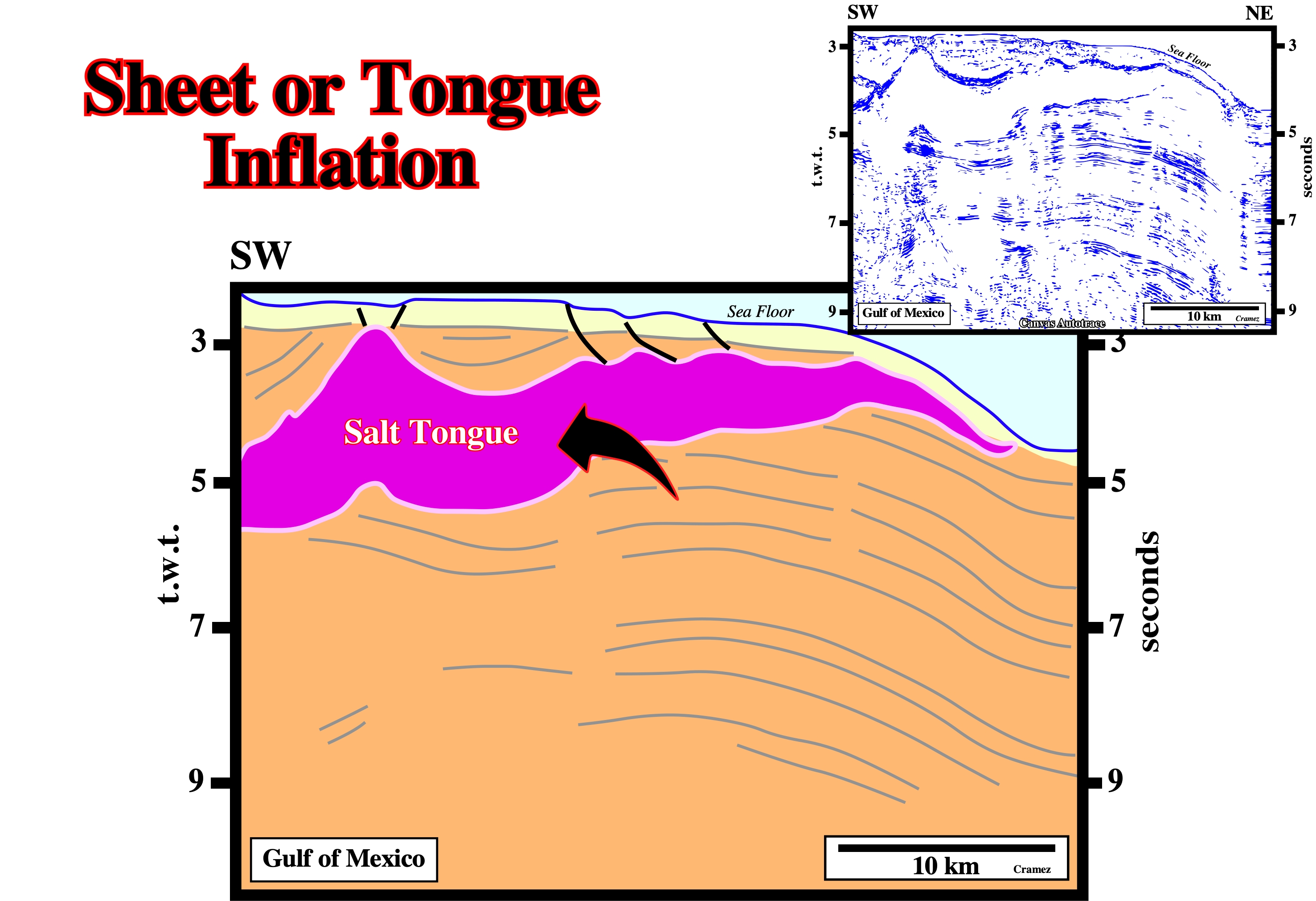
In the Gulf Coast, as illustrated above, the majority of the allochthonous salt structure have been inflated mainly due to differential loading.
Sheet Injection
Process in which salt laccoliths and salt sills are emplaced as thin sheets between overburden strata a few hundred meters or less below the sediments. Injection is driven by gravity spreading through weak, unconsolidated, mud-rich, less dense overburden under low confining pressures. Synonym of sheet spreading.
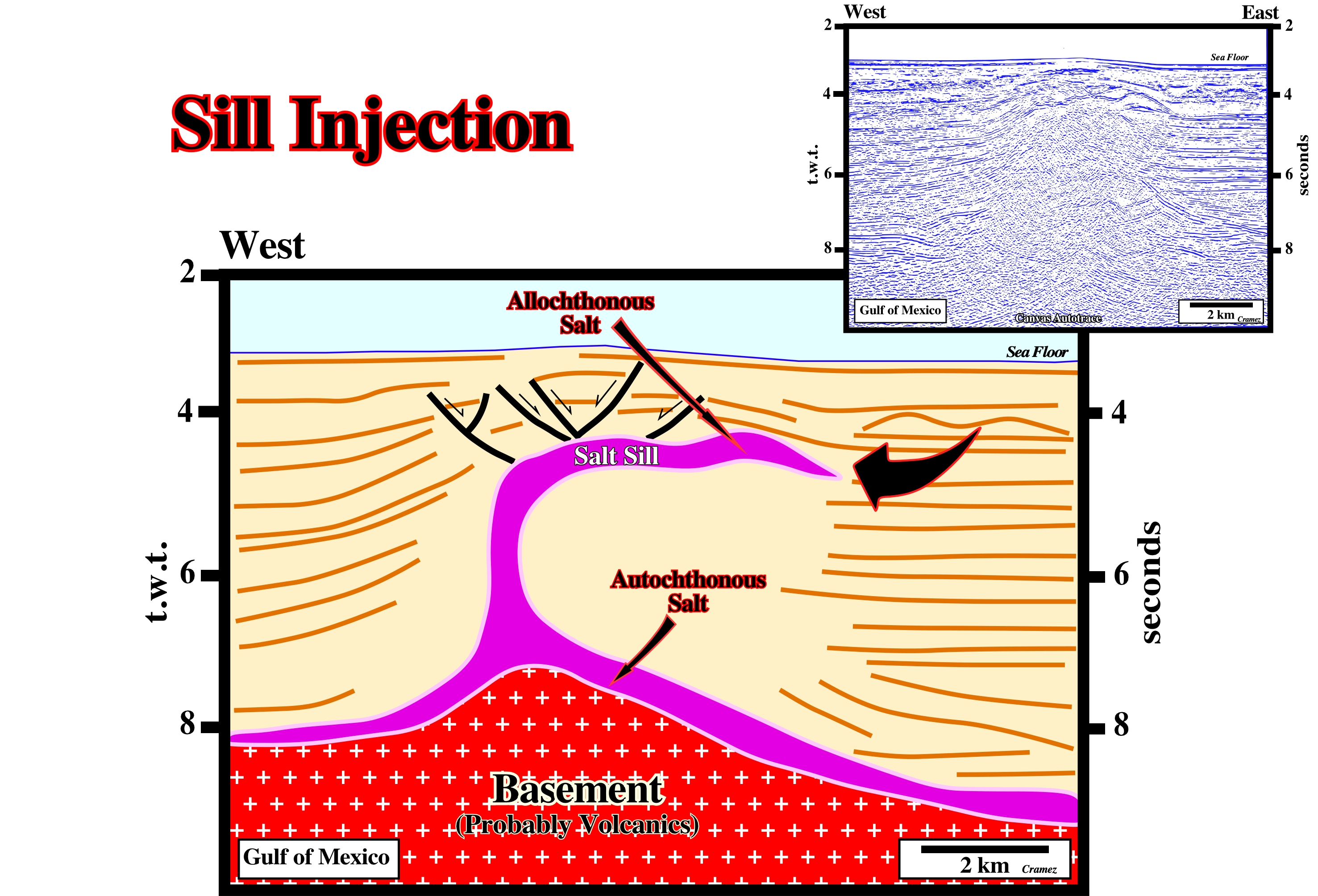
On this preliminary tentative interpretation of a Canvas autotrace of a GOM line, it is quite evident the allochthonous salt structure was created by salt injection under relative thin sedimentary cover (thinner than presently).
Sheet Segmentation
Partitioning of a salt sheet into separated salt structures during reactivation by subsidence of intrasalt basins or by growth faulting.
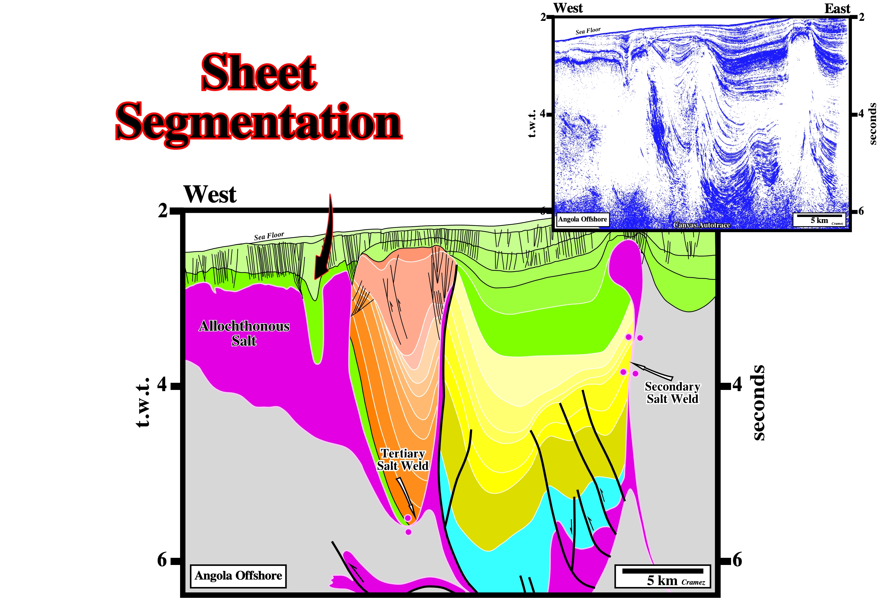
As illustrated on this preliminary tentative interpretation of a Canvas autotrace of an Angola offshore seismic line, the original salt sheet is splitting up by a progressive westward development of salt expulsion basins. The counter-regional faults, in the central part of the line, is the ramp or the feeder of the salt sheet.
Sheet Spreading
Synonym of Sheet injection.
This regional cross-sections through the Gulf of Mexico indicates the sheet spreading was done at different level since at least two generation of salt nappes can be recognized. The sheet spreading is done by salt injection driven by gravity spreading through weak, unconsolidated , mud-rich, less dense overburden under low confining pressure. As indicating, in the southern part of the cross section, the original seismic data is quite poor and any tentative interpretation between the autochthonous salt and the 1st generation salt nappe (allochthonous salt) is possible, what is not the case, in the northern par of the section.
Shelf
Part of the offshore that is between the shoreline and the continental slope. Synonym of platform or continental shelf.
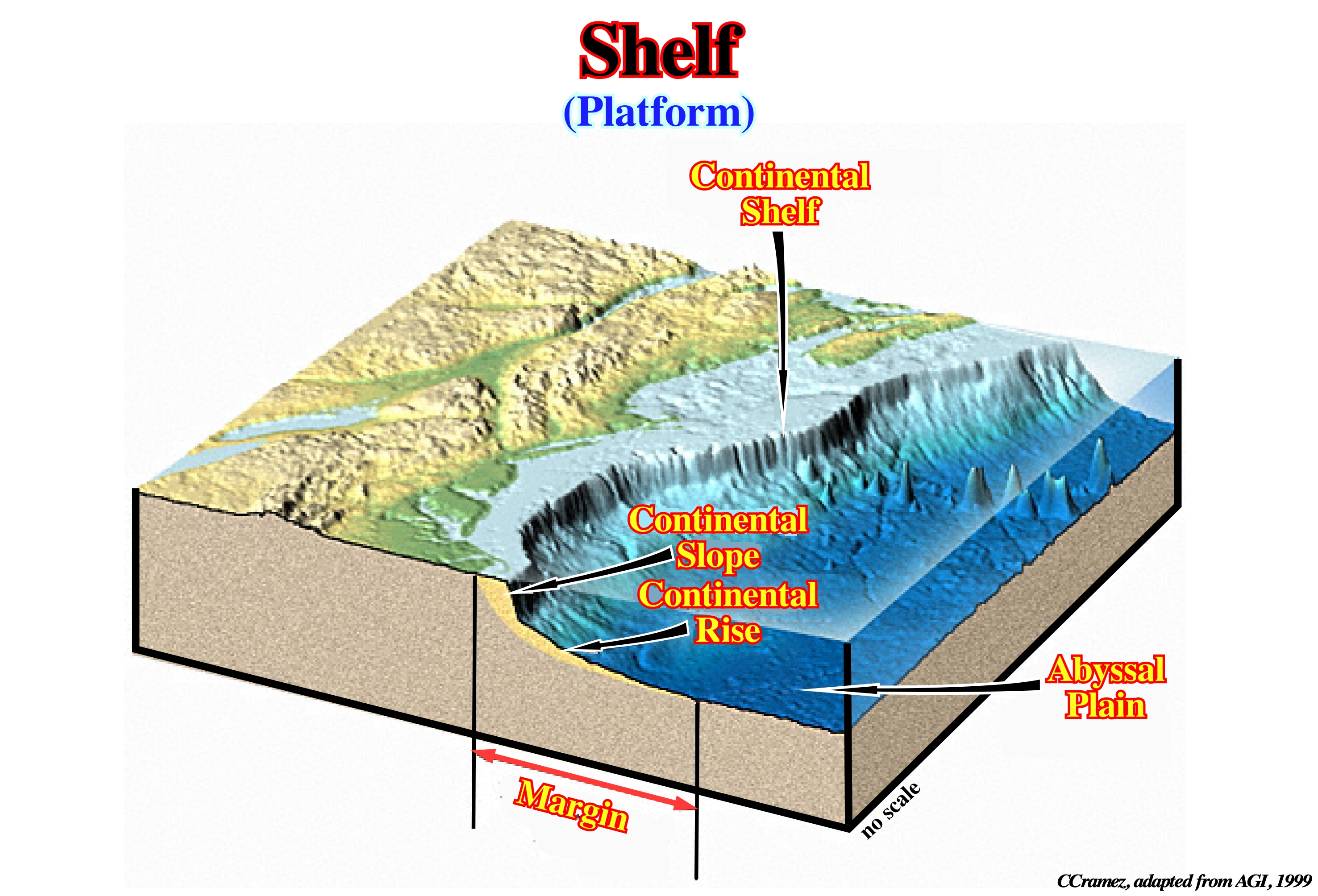
During certain geological periods of the evolution of a basin, the shelf, in which the water depth ranges between 0 and 200 m, can disappear. In fact, in a sequence-cycle, in lowstand geological conditions (sea level below the basin edge), the basin as no shelf. On the contrary, in highstand geological condition, i.e., when the sea level is above the basin edge, the basin as a shelf (platform). The shelf extension is maximum at the peak of a transgression (set of increasingly important marine ingressions and increasingly smaller sedimentary regressions), but it becomes almost nil during the last phase of regressive episode (see "Shelf Break").
Shelf Break
The limit between the shelf and the continental slope (in a transgressive setting). In a mature regressive setting (when the basin has no shelf), the shelf break becomes the depositional coastal break and so the shelf break becomes, roughly, coincident with the shoreline.
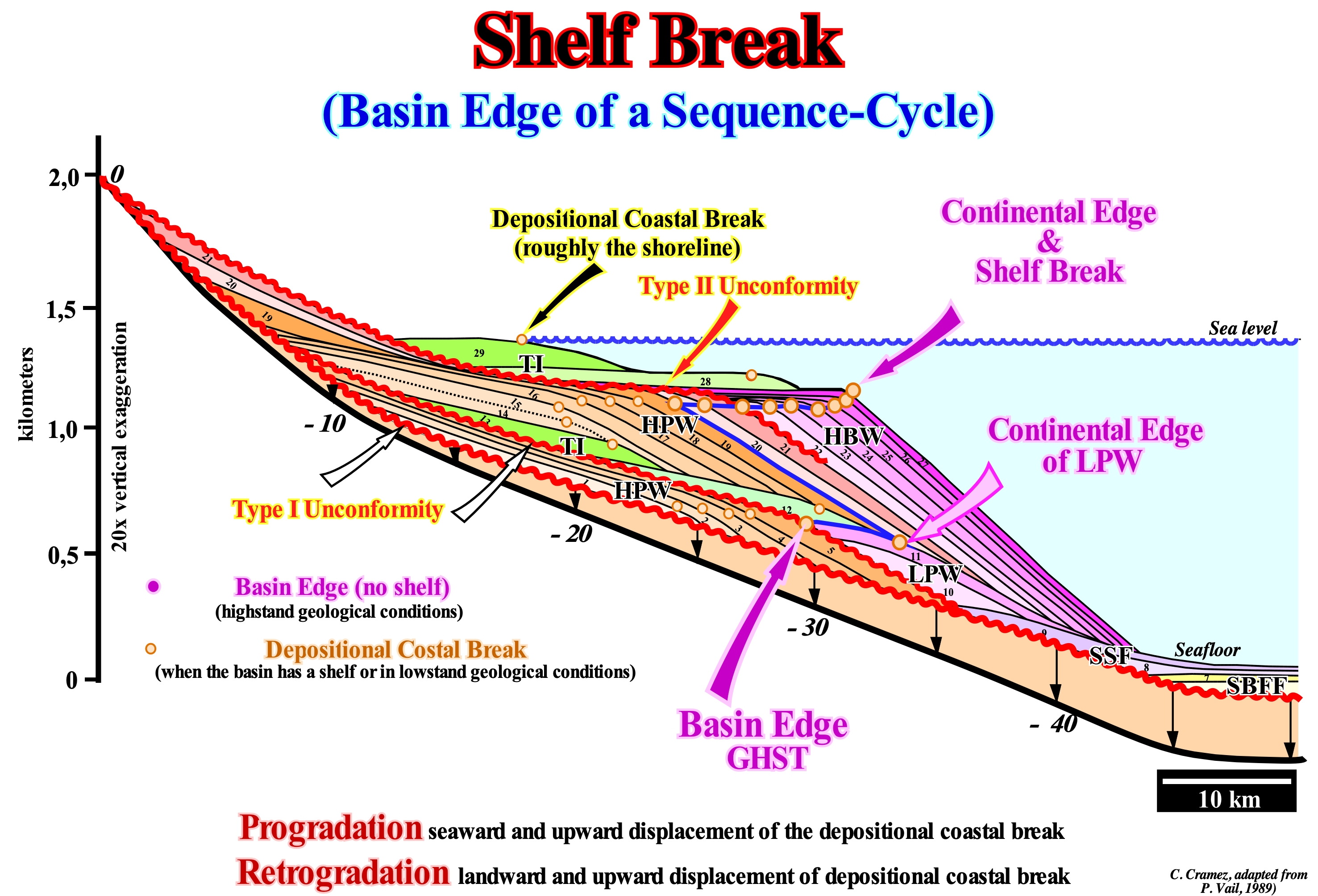
In the lowstand systems tracts of a sequence-cycle, in a ramp geological basin context, to speak of the continental edge does not make sense, since there is a gradual passage between the shoreline and the deep environments. On the contrary, in a growth faults geological basin context, the continental edge corresponds, more or less, to the position of the fault plane (intersection with the surface), whereas in an abrupt morphological geological basin context, such as during lowstand prograding wedge (LPW) or during the bordering prograding wedge (BPW), shown in this figure, the location of the continental edge is, relatively, easy. As can be seen in this sketch, during a sequence-cycle, the location of the basin edge is variable. The basin may or may not have a shelf (continental platform). When the basin has a shelf, the continental edge is the basin edge. When the basin does not have a shelf , the basin edge is the last continental edge of the preceding sequence-cycle. The continental edge is not the basin edge during the deposition of the lowstand systems tracts subgroups, i.e., during the deposit of the submarine basin floor fans (SBFF), submarine slope fans (SSF) and the lowstand prograding wedge (LPW). During the deposition of these subgroups of sedimentary systems tracts, the basin edge is the last basin edge of the preceding sequence-cycle. However, during the 2nd stage of development of the highstand prograding wedge (HPW), when the basin ceases to have a shelf, as long as the progradations of the the highstand prograding wedge, completely, fossilize the platform and the shoreline became, practically, coincident with the new continental edge, which continues to be the basin edge. In the sketch illustrated in this figure, during the highstand prograding wedge (1, 2, 3, 4 and 5) of the lower sequence-cycle, the basin edge is marked by successive continental breaks, which coincide, roughly, with the shoreline, once the basin has no shelf (this scheme is exaggerated, vertically, about 20 times). Since the relative sea level fall, the shoreline moved seaward and downward, raising (relatively) the old coastal wedge (coastal prism) exhuming the upper part of the former continental slope creating an unconformity (in red). The sea level was thus lower than the old basin edge (5), which continues to be the basin edge during the deposit of the lowstand systems tracts group (LSTG) of the new sequence-cycle: a) Submarine basin floor fans (SBFF), 6 and 7 ; Submarine slope fans (SSF), 8 and 9) and lowstand prograding wedge (LPW), 10 and 11. From the first flooding surface, the basin edge becomes the last continental edge of the lowstand prograding wedge (11), since the basin, due to flooding of the coastal plain of the lowstand prograding wedge, the basin get a shelf (continental platform). During the transgressive interval (TI), whose geometry is retrogradational, the basin edge continues to be (11), since the depositional coastal break of the depositional surface (more or less the shoreline on seismic lines) moves continentward creating a shelf with increasing extent and water-depth (12, 13, 14 and 15). Since the relative sea level* begins to rise, in deceleration, the highstand prograding wedge (HPW) begins to settle down, decreasing, progressively, the platform size (16, 17, 18 and 19), at the same time as the depositional coastal breaks of the depositional surface (shoreline) approaches the continental edge. As soon as the basin has no more platform (19), the old basin edge is fossilized by the slope deposits (2nd stage of development of the highstand prograding wedge). The shoreline is, more or less, coincident with the continental edge, i.e., and the basin edge changes from (11) to (19). During the development of the highstand prograding wedge (HPW) and bordering prograding wedge (BPW), the basin edge passes, successively, from 20 to 27 until a relative fall creates a new erosional surface (unconformity),which is, later, fossilized by the deposition of transgressive interval (28, 29).
(*) Local sea level referenced to any fixed point on the Earth's surface, whether it is the base of the sediment (top of the continental crust) or the sea floor. It is the result of the combined action of the absolute (eustatic) sea level, supposed to be global referenced to the Earth's centre and tectonics (subsidence or uplift of the sea floor, for instance).
Shelfal Accommodation
The water depth of the platform is the space available for the sediments or shelfal accommodation. When there is a relative sea level rises (eustasy + subsidence), shelfal accommodation increases, and so, there is deposition. Deposition is equal to shelf accommodation increasing minus the water depth deposition. When the relative sea level falls, the shelf accommodation decreases, and so, there is no deposition. If the relative sea level falls below the shelf break, the shelf is exposed, erosion takes place and unconformity is formed and there is deposition of turbidites in the deepest part of the basin.
The space available for sediment or accommodation, as some geoscientists say, just makes sense the upstream basin edge (shelfal accommodation). Seaward of the basin edge, the water-depth is, always, greater than 200 m (there is always enough water-depth the deposition of the deep-water depositional systems). Relative sea level changes do not have a large effect on deep-water deposition, except when the relative sea level falls below the basin edge (turbidite depositional systems). Do not forget that there are two types of sea level: (i) Relative Sea Level, which is a local sea level, referenced to the base of the sediment (top of the continental crust) or to the sea-floor and (ii) Absolute Sea Level or Eustatic Sea Level, which is supposed to be global, is referenced to the Earth's centre. The relative sea level is the result of the combination of absolute (eustatic) sea level and tectonics (subsidence or uplift of the sea-floor). Submarine basin floor fans (SBFF) and submarine slope fans (SSF) are the subgroups of systems tracts deposited during significant relative sea level falls. In contrast, upstream of the basin edge, which may or may not coincide with the continental edge (coincides with the depositional coastal break when the basin has a shelf), relative sea level changes control the deposition. An increase in available space (accommodation) induces deposition and a decrease induces erosion. It is important to consider whether the basin has a shelf or not. In the case of a basin with a shelf, i.e., when the depositional coastal break (more or less the shoreline) is upstream of the continental edge (which in this case coincides with the basin edge), a relative sea level rise increases the available space and thus there will be deposition. If the terrigeneous influx is sufficient, all of the space created will be filled during the period of stability of relative sea level that occurs after each marine ingression and the water-depth will remain constant. If the sedimentary supply is not enough to fill the entire space created by the increments of the relative sea level rise (marine ingressions or eustatic paracycles), there will be deposition, but the water-depth will increase, since only a part of the available space created is filled. When the basin has no shelf, the shoreline coincides, roughly, with the upper limit of the continental slope (continental edge), which may or may not coincide with the basin edge (it coincides with the basin edge under highstand geological conditions). Under lowstand geological conditions, the basin edge is, largely, upstream of the continental edge as well as of the shoreline. In this case, several hypotheses are possible: (a) If the available space, created by the relative sea level rise, is completely filled, the water column (water-depth) is zero ; (b) If the available space (accommodation) is not completely filled, a continental shelf is formed with the beginning of transgressive interval deposition ; (c) If the available space is insufficient to accommodate all the sedimentary supply, a part of the sedimentary particles will be deposited on the upper sector of the continental slope and the trigger of turbidite currents is possible. The cyclicity of the available space is induced by eustasy. The rate of eustatic variations is much higher than the rates of tectonic variations. The accommodation magnitude is, mainly, given by tectonics (subsidence or uplift of the sea-floor). As shown in the photograph of this figure, within a sequence cycle, to have deposition (except for turbidite deposits) the available space must always increase. It increases in acceleration during the lowstand prograding wedge (LPW) and during a transgressive interval (TI) and in deceleration during the highstand prograding wedge (HPW). As long as the available space for the sediments decreases, significantly, an unconformity (erosional surface) is formed. As illustrated in this figure, each sequence-cycle is represented just by the highstand systems tracts group* (HSTG), i.e., by the systems tracts forming the sub-groups known as transgressive interval (TI) and highstand prograding wedge (HPW).
(*) Within a complete sequence-cycle there are two groups of systems tracts: (i) Highstand Systems Tracts Group (HSTG) ans (ii) Lowstand Systems Tracts Group (LSTG). The highstand systems tracts group is composed by two sub-groups: (i.1) Transgressive Interval (TI), at the base and (i.2) Highstand Prograding Wedge (HPW), at the top. The lowstand systems tracts group is formed by three sub-groups that from the bottom to top are: (ii.1) Submarine Basin Floor Fan (SBFF) ; (ii.2) Submarine Slope Fan (SSF) and (ii.3) Lowstand Prograding Wedge (LPW). Each sub-group of systems tracts is formed by one or several systems tract function of the number of marine ingression (LPW, TI and LPW) and turbiditic currents (SSFF, SFF).
Shelfal Sediments
Sediments deposited under a water-depth ranging between 0 and 200 meters. Synonym of platform or shallow water-depth deposits.
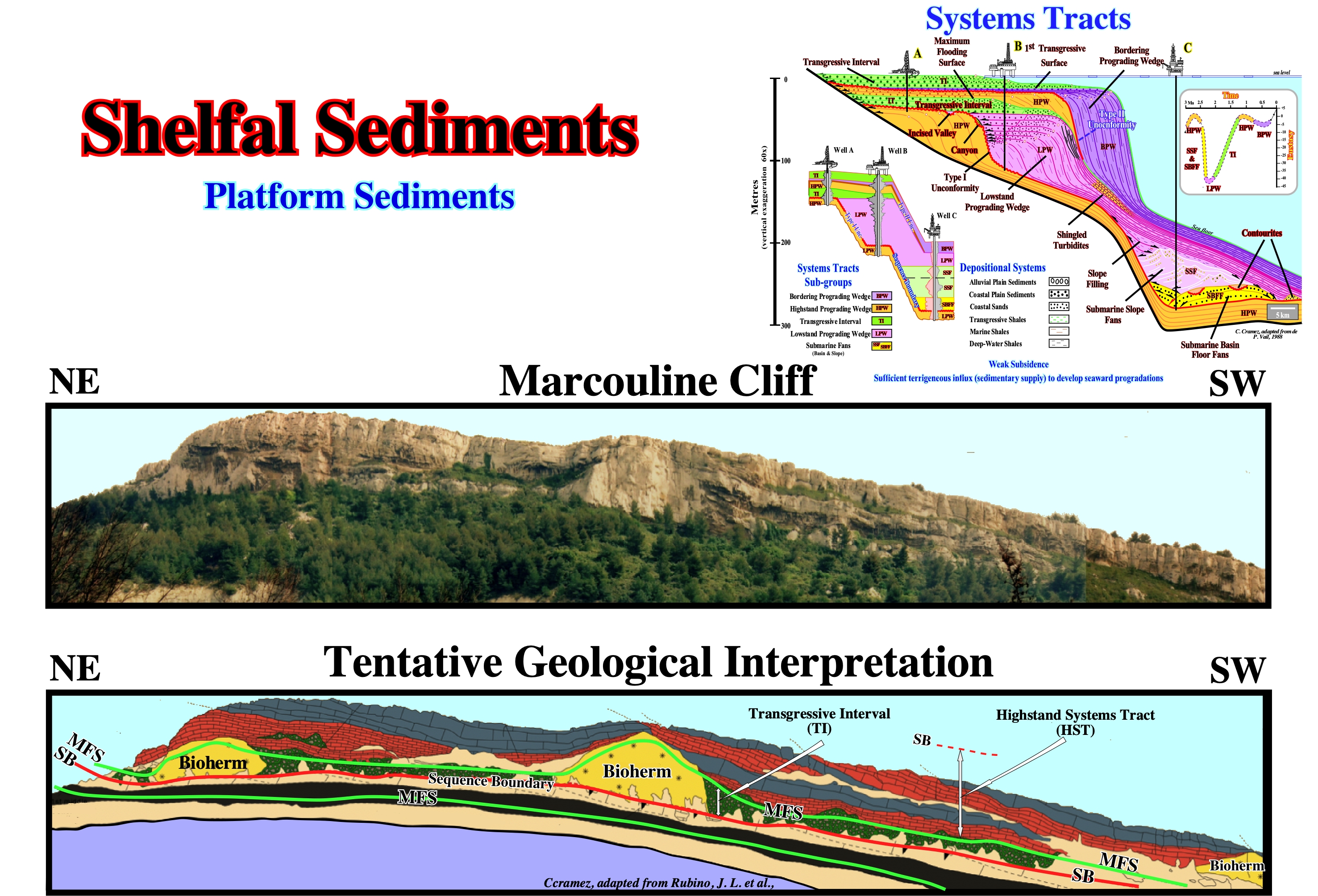
In this sketch are summarized the basic principles of sequential stratigraphy, when this is done at the hierarchical level of the sequence-cycles. These stratigraphic cycles are deposited in association with the 3rd order* eustatic cycles, which last between 0.5 and 3-5 million years and are, probably, induced by glacio-eustasy (variation of the global level of the sea due to increase or decrease the total volume of water stored in the oceans due to the formation or melting of ice on the continents) and tectonics (subsidence or uplift of the sea floor). The variations induced by the formation and melting of the ice seas have an influence, not only small and local, but above all contrary to that of the ice caps, since ice is less dense than water. Sequence-cycles with all other stratigraphic cycles are limited by unconformities (erosional surfaces induced by significant relative sea level falls). In addition the age difference between the lower and upper unconformities must be between 0.5 and 3-5 Ma, so that the interval is associated with a 3rd order eustatic cycle. Sequence-cycles are formed by different sedimentary systems tracts (lateral chains of contemporary depositional systems and genetically deposited during a certain segment of the curve of the relative sea level changes that induce the sequence-cycle, as illustrated in the Time / Eustasy diagram). It is important to note, that in the model illustrated in this figure, the subsidence parameter of the sea floor is zero, i.e., all available space for sediments (accommodation) is created by absolute sea level changes (upstream of the continental edge the chronostratigraphic lines are horizontal). That is why the sea level changes in the diagram Time versus Eustasy (absolute sea level curve). As illustrated, upstream of the edge basin, an exploration well (well A) just recognizes the sedimentary systems tracts sub-groups deposited at highstand geological conditions that form the highstand systems tracts group, that is, the transgressive interval (TI) and the highstand prograding wedge (HPW). In deep water (wells B and C) the lowstand systems tracts group (LSTG), which is formed by three systems tracts sub-groups: (i) Submarine basin floor fans (SBFF) ; (ii) Submarine slope fans (SSF) and (iii) Lowstand prograding wedge (LPW), is predominant. The other systems tracts sub-groups, which form the highstand systems tracts group, i.e., the transgressive interval (TI) and the highstand prograding wedge (HPW), are very condensed. The bordering prograding wedge (BPW) also called the subgroup of descending systems tracts (DST) in the P. Vail model is separated from the sequence-cycle by a type II unconformity. This type of unconformity, which the EPR (Exxon Exploration Production Research) geoscientists defined in the 1970s in association with a small relative sea level fall that does not put sea level lower of the basin edge, i.e., that exhumes, just, part of the platform, fell in disuse. In the field, but especially on seismic lines, it is very difficult to individualize, which means that the systems tracts of the bordering prograding wedge has, practically, disappeared from the literature of sequential stratigraphy. They form, at large extent, what is now called forced regression. Hunt and Tucker (1992) highlighted the importance of the architecture of the coastal deposits settle down during the relative sea level fall and incorporated the bordering systems tracts at the top of the sequence-cyle, that is to say, the boundary unconformity is placed above and not under the systems tracts the bordering prograding wedge (BPW). For them, although the sub-aerial unconformity starts at the beginning of the falling phase, erosion and incision continue until the end of the falling phase of sea level. An important distinction is now made between regression and forced regression. In both processes there is a decrease in accommodation in relation to the rate of terrigeneous influx. However, a (normal) regression occurs when the rate of increase in accommodation is smaller than the rate of sedimentation, whereas in a forced regression, which is a specific case, accommodation decreases due to a relative decrease in sea level (the shoreline moves basinward and downward). Forced regressions are independent of terrigeneous influx changes.
(*) The term "3rd order eustatic cycle" is somewhat abusive since these cycles correspond to variations of relative sea level and not eustatic or absolute sea level which is global and referenced to the Earth's centre.
Shield
A large area of exposed basement rocks in a craton, commonly with a very gently convex surface, surrounded by sediment-covered tectonic platforms, as the Canadian Shield or Baltic Shield. The rocks of virtually all shields areas are Precambrian.
Usually, the cratons or shields are regions of stability where during long geological periods the formation of mountains does not occur. They form the nucleus of the continents or the substrate of ocean basins. They may be, partially, covered by thinly sedimentary layers such as in Central Asia and in the central part of North America. Sometimes they are surrounded by young mountain ranges made up of very deformed sediments, called orogens* (tectonic province where several geological processes related to the confrontation of lithospheric plates and the origin of the Earth's great mountainous belts). In this case, certain geoscientists speak of platform. The cratons can be deformed by faulting, but hardly by folds, particularly the inner part. The process by which the cratons are formed is called cratonization, which can be defined as the gradual transformation, from the end of the Archean, of unstable areas into stable areas, which are differentiated function of the movement rate in a given time interval. The craters are sub-divided, geographically, into geological provinces (spatial entities with common geological attributes). A geological province may include a single dominant structural element such as a structural basin, a mountain range or a number of contiguous related elements. Adjacent geological provinces may be similar from a structural point of view, but can also be considered, separately, when they have different geological histories. In Northern Hemisphere, the most important cratons are: (i) Angara (Western Siberia crater) ; (ii) Scandinavia (encompassing Northern Europe) and (ii) Canadian Shield (encompasses the northern regions of Saskatchewan, Manitoba, Ontario and Quebec, as well as most of Labrador). In Southern Hemisphere, the main cratons are: (a) African (encompasses five continental masses, from the Precambrian, which came together at the end of Precambrian and early Paleozoic to form the African continent: West Africa, Kalahari, Congo, Sahara and Tanzania) ; (b) Antarctic (covering about 10 Mkm2, that is to say, 73% of the Antarctic continent, but is almost entirely buried by the Antarctic East ice cap ; it is formed by Mawson craton and several other marginal cratons) ; (c) Australian (composed of a whole series of craters including: Altjawarra, Central, Curnamona, Gawler, Pilbara, Yilgarn, etc.) and (d) Brazilian (the Guiana craton (Roraima is shown in this figure) and Central Shield of Brazil constitute, respectively, the exhumed parts of the north and south of the craton ; smaller cratons are found southward, as the Plata River craton and San Francisco craton). The first large cratons formed during the Archean, when the terrestrial heat flux was probably about three times greater than today. The concentration of radioactive isotopes and the residual heat were very large. The tectonic and volcanic activity were also very large. The earthly mantle was much more fluid and the crust finer. All this contributed not only to a very rapid formation of the oceanic crust, in the mid-oceanic ridges** and in the hot spots (thermal anomalies in the interior of the Earth, associated with convection systems of the mantle and responsible for the volcanism occurring in the interior lithosphere plates), but also to a rapid recycling of oceanic crust in B-type or Benioff subduction zones (when an oceanic lithosphere plate dips under a continental lithosphere plate). The Earth's surface was, probably, broken up into relatively small lithospheric plates (tectonic plates) with many islands and oceanic or continental volcanic arcs (chain of mountains or volcanic islands formed in B-type subduction). Small protocontinents (cratons) formed as the crust rocks were melted by the hot spots and recycled in the subduction zones of Benioff. Certainly, there were no large continents in the Archaic. Small continents were predominant, since coalescence was difficult due to the high rate of geological activity.
(*) The orogenic belts are divided into two regions: (i) Hinterland, which is the domain of large vertical deformations and magmatism and (ii) Borderland, which is the domain of the tectonics of shortening by thrusts (scales) and the great thrusts with deformations and metamorphism that attenuate towards the foreland basins. An accretion orogen is associated with a B-type subduction zone (Benioff), such as the Andes, whereas a collision orogen is associated with an A-type subduction zone (Ampferer), such as the Alps or the Himalayas.
(**) Large submerged mountain ranges, located in the central part of the Earth's oceans, resulting from the oceanic spreading between lithospheric plates, whose height above the surrounding ocean floor is about 2000 to 3000 meters. In the central region of a mid-oceanic ridge there is an axial groove, called "rift" (which has nothing to do with the riff-type basins of the classification of the sedimentary basins of Bally and Snelson) along which lava rise from magma of the sublithospheric mantle.
Sigsbee Escarpment
The bathymetric expression of salt flows that have overridden the abyssal plain of the Gulf of Mexico tens of kilometers since the Paleogene.
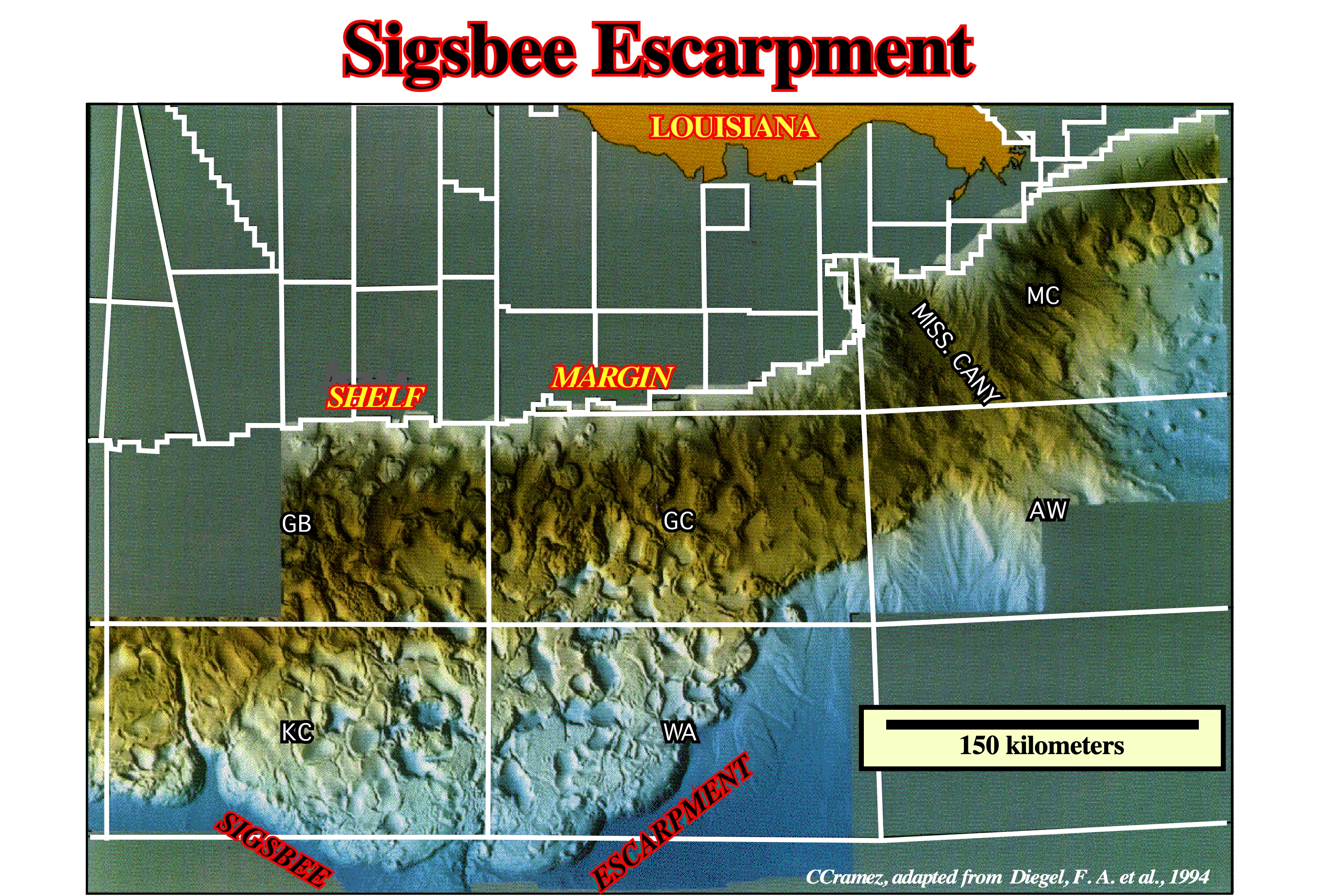
As illustrated on this map of bottom of the sea, the Sigsbee Escarpment is, by far ,the more characteristic bathymetric feature in Gulf of Mexico. Salt expulsion basins, as well as, sutures of allochthonous salt structures can, easily, be predicted.
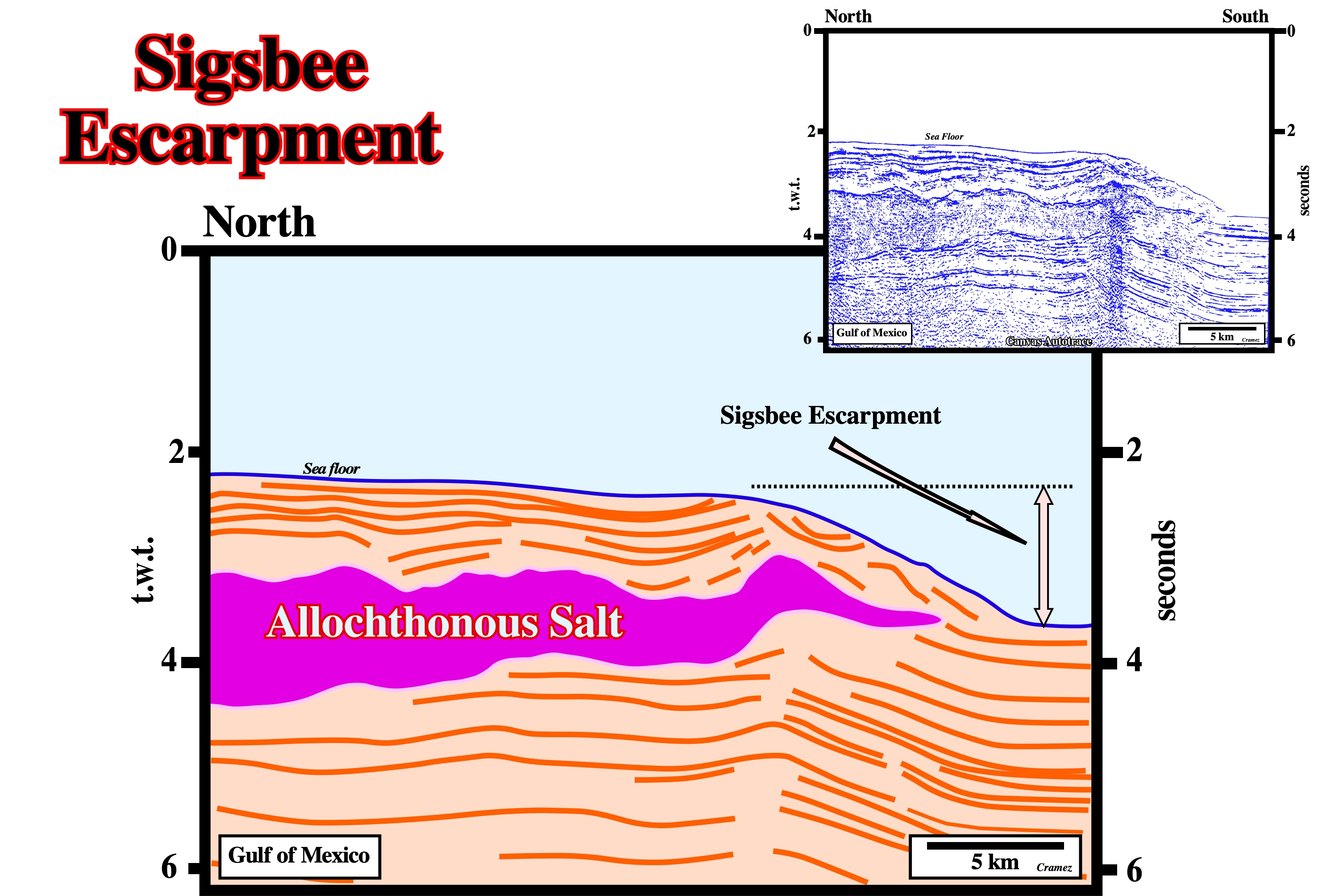
Seismic expression of the Sigsbee Escarpment. The main driving mechanism of such bathymetric features is well illustrated on this tentative interpretation of a Canvas autotrace of a Gulf of Mexico seismic line.
Silurian Salt Deposits
Late Silurian age is, widely, accepted as the period of considerable salt accumulation. This is based, chiefly, on information concerning Michigan-Appallachian basin, where thick salt sequences are widespread in North America. Three salt-producing silurian evaporite basins, namely, the Dniester-Prut, Lena-Yenisei and Carnavon basins can be outlined.
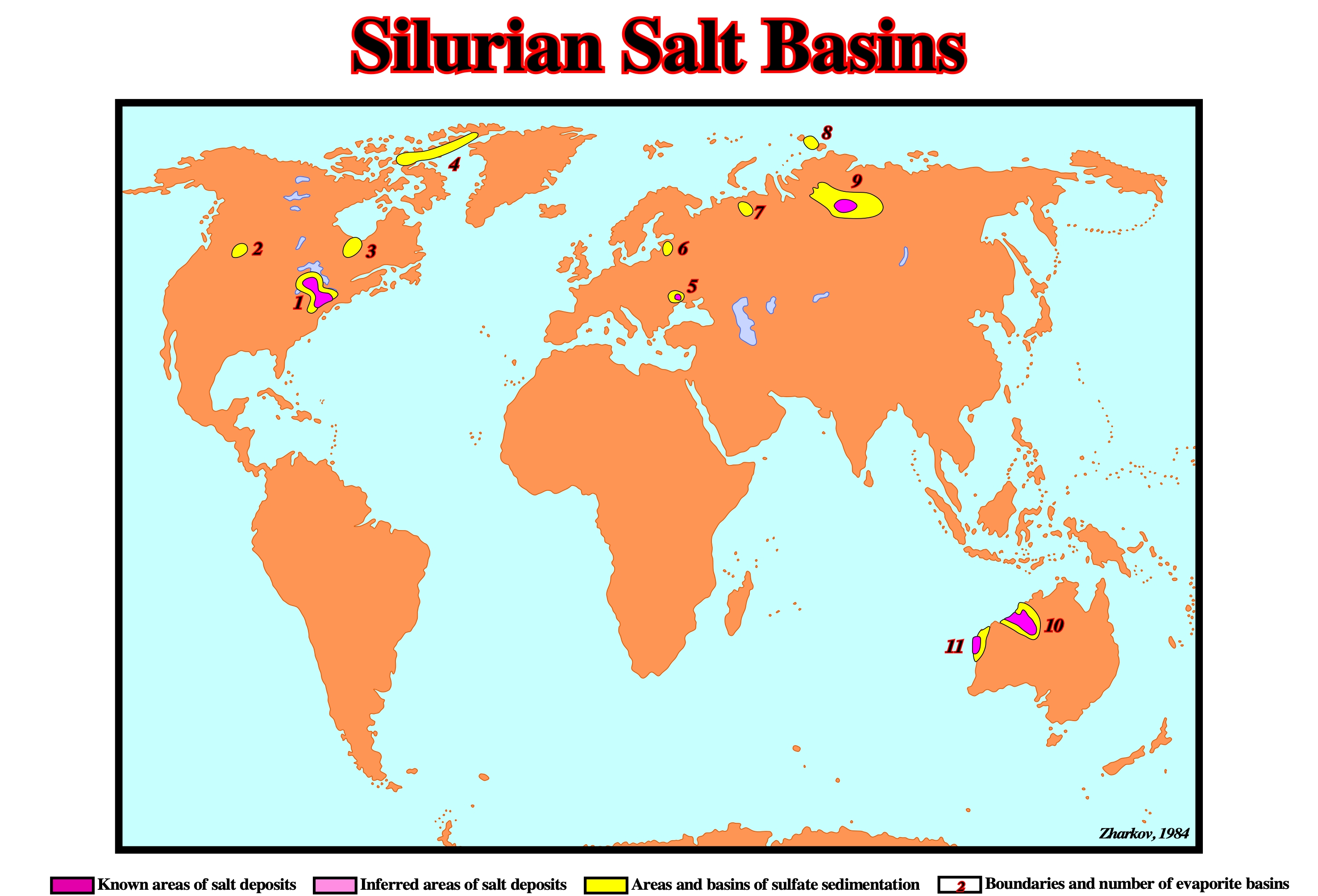
The distribution of Silurian evaporite geographic basins can be summarized as follows: (1) Michigan-Appalachian ; (2) Williston ; (3) Moose River ; (4) Canadian Archipelago ; (5) Dnister-Prut ; (6) Baltic ; (7) Pechora ; (8) Severnaya Zemlya ; (9) Lena-Yenisei ; (10) Cannin ; , (11) Carnavon.
Skirt
Downward-facing synformal anticline fringing the bulb of a mushroom diapir and made up of deformed evaporites that envelop the stem of the diapir.
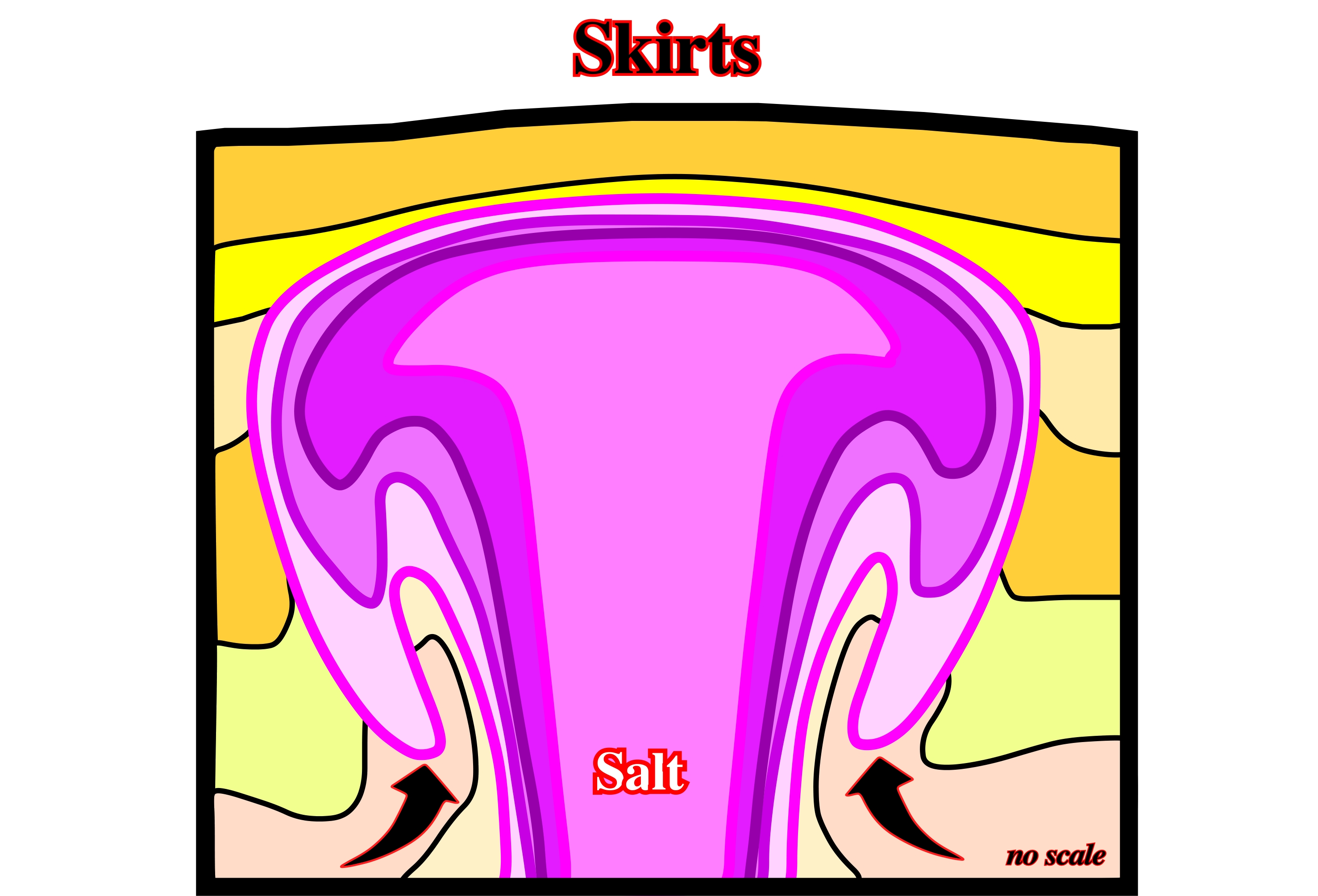
Skirts are difficult to recognize on seismic lines, but relatively easier to identify on time slices at appropriated depth (see mushroom diapir)
Source Layer
Layer supplying salt for the growth of salt structures. Source layer is often taken as a synonym of mother source layer.
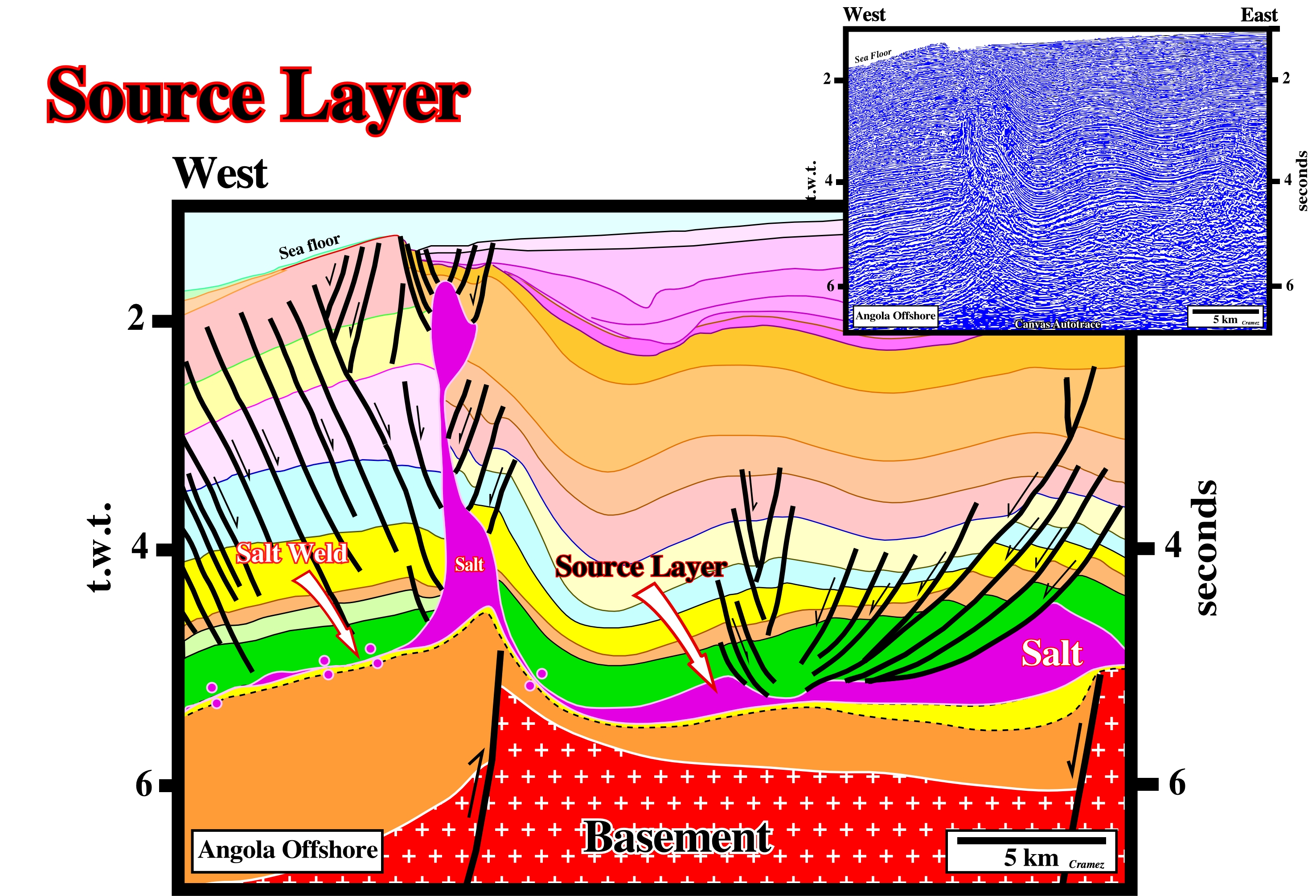
In Angola offshore, as well as in onshore, the salt source layer is the autochthonous Aptian salt, which stratigraphically speaking was deposited above the Cretaceous basal sandstones (lower yellow, Cuvo and Chela formation) of the divergent margin and below the Albian limestones (green, Binga and Pinda formations). In Angola-Gabon and Brazil, the source layers are different. Contrariwise to an erroneous hypothesis, still followed by some geoscientists, these Aptian salt geographic basins were always individualized by subaerial and oceanic spreading centers.
Space Available for Sedimentation
Roughly speaking, the water-depth. Synonym of accommodation. Sedimentation takes place, every time, there is an increasing of the space available, i.e., a relative sea level rise.
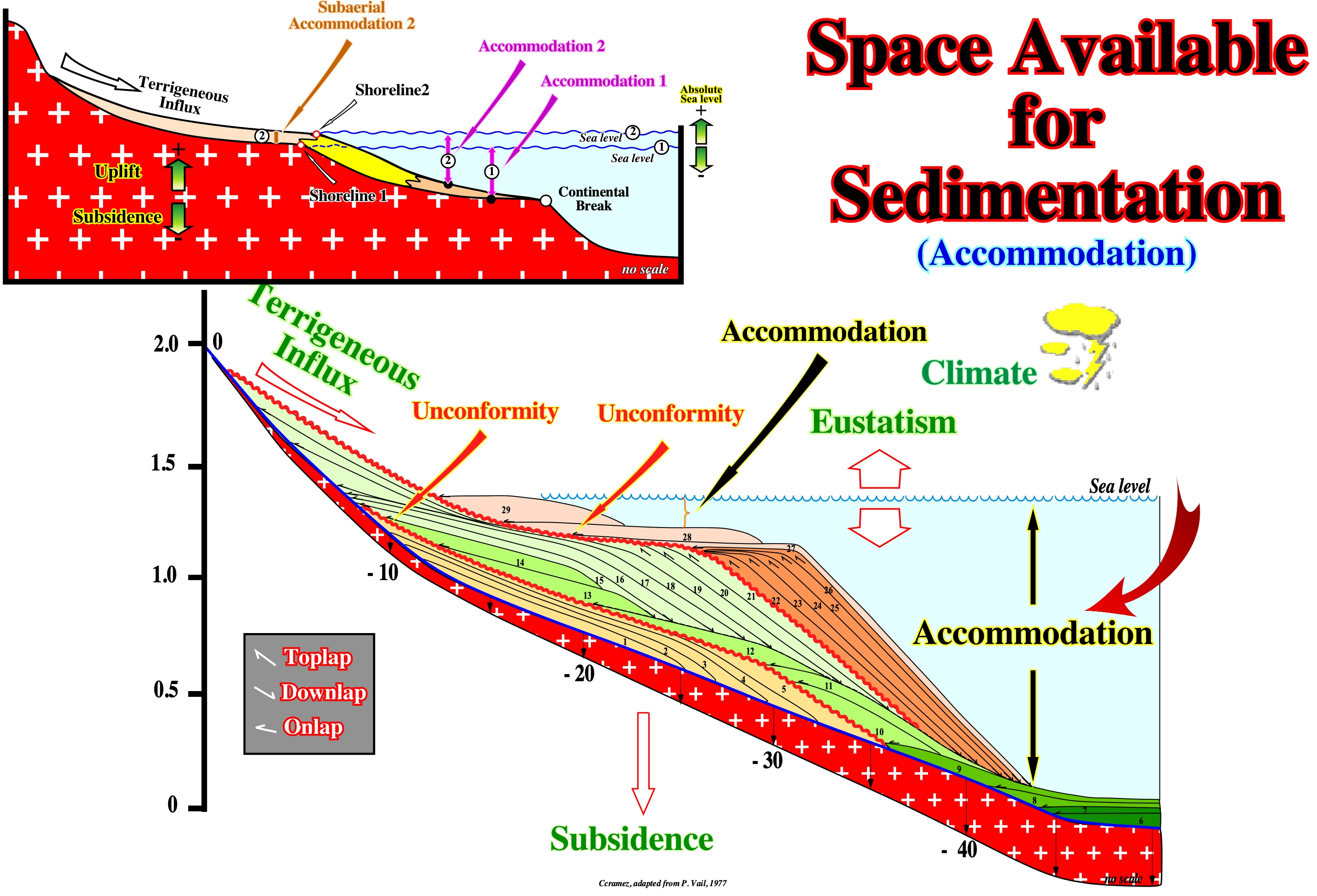
The accommodation or available space for the sediments varies with the relative sea level changes. Within a sequence-cycle, seaward of the shoreline, the accommodation is marine. Upstream of the shoreline, which is, more or less, the depositional coastal break of the depositional surface, the accommodation is subaerial (scheme on the upper left). When there is a relative sea level rise, the water-depth increases and, in general, there is deposition (mainly upstream of the depositional coastal break) during the stability period of the relative sea level that occurs after each eustatic paracycle or, in other words, after each marine ingression. On the contrary, when there is a relative sea level fall, the water-depth decreases and, in general, there is erosion or a forced displacement seaward and downward of the coastal deposits (forced sedimentary regression), particularly, landward of the basin edge. Erosion occurs when the relative sea level fall is significant and puts the sea level below of the basin edge, which is the continental edge during the transgressive interval (TI) and during the 1 st phase of the development of the highstand prograding wedge (HPW), i.e., during the highstand systems tracts group (HSTG). A forced regression (deposition of descending depositional systems in the early terminology of P. Vail) occurs when the relative sea level fall is insufficient to exhume the shelf and bring the sea level lower than the basin edge. Within a stratigraphic cycle and, particularly, within a sequence-cycle, one should not confused the basin edge, which corresponds, generally, to the continental edge (or continental break) with the depositional coastal break, which corresponds, roughly, to the shoreline. During the deposition of the lowstand systems tracts subgroups (submarine basin floor fan, submarine slope fan and lowstand prograding wedge) the basin edge is the last continental edge of the preceding sequence-cycle and the sediments are deposit against the continental slope. According to P. Vail, submarine basin floor fan (SBFF) and the submarine slope fan (SSF) deposit, when the relative sea level falls, significantly, and the shelf (if it existed) and the upper part of the continental slope are exhumed. All other sedimentary systems tracts subgroups forming a sequence-cycle, are deposited during the stability periods of the sea level occurring after each marine ingressions (rises of relative sea level). The sea level, which, can be relative or absolute (eustatic), can rise or fall in acceleration or deceleration. The relative sea level is a local sea level referenced to any point on the Earth's surface which is, generally, the top of the continental crust (base of the sediments) or the seafloor. On the contrary, the absolute (eustatic) sea level is supposed global and referenced to the Earth's center. In a sequence-cycle, when the relative sea level rises in acceleration are deposited: (i) The lowstand prograding wedge (LPW) and (ii) The transgressive interval (TI). When the relative sea level rises in deceleration, is deposited the highstand prograding wedge (HPW). In addition to accommodation, the other parameters controlling the depositional systems are: (i) Eustasy (variations of absolute or eustatic sea level) ; (ii) Tectonics (subsidence or uplift of the sea-floor) ; (iii) Climate and (iv) Terrigeneous Supply. Climate is quite important and climatic changes are a reality. They exist since the Earth was formed about 4.5 Ga. In a sedimentary stratigraphic section, any alternation between a sand bed or group of beds of sand and a shale or a limestone bed or group of beds is a direct or indirect consequence of a climatic change, which implies, at least, a relative sea level rise (combination of absolute sea level and tectonics). The unconformities (erosional surfaces), which bound the stratigraphic cycles (induced by eustatic cycles) are quite often caused by glacio-eustasy, particularly, when they limits sequence-cycles (induced by 3rd order eustatic cycles, whose time-duration ranges from 0.5 to 3-5 My). Between the sequence-paracycles (deposited in association with the marine ingressions that characterize eustatic paracycles) there are no unconformities, that is to say, there are no relative sea level fall. Sequence-paracycles are limited by flooding and ravinement surfaces. Within a sequence-cycle, seaward of the continental edge (whether or not it coincides with the basin edge) accommodation (available space for sediments) is sufficient for deposition of submarine fans, sedimentary aprons, pelagic (water-depth greater than 1,000 m) and hemipelagic (water-depth between 200 and 1,000 m) deposits.
Spilite Greenstone
Altered basalt, characteristically, amygdaloidal or vesicular, in which the feldspar has been albitised.
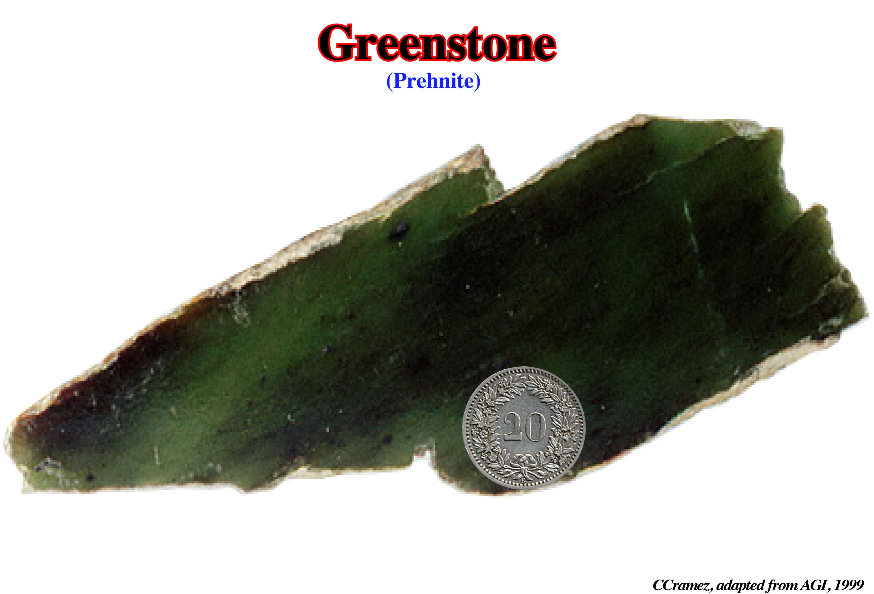
Typically, a spilite greenstone is accompanied by chlorite, calcite, epidote, chalcedony, prehnite, or other low-temperature hydrous crystallization products characteristic of a greenstone.
Spine
Steep-sided mass of salt within larger salt body that moves or has moved faster or slower than neighboring spines from which it is separated by boundary shear zones or internal shear zones.
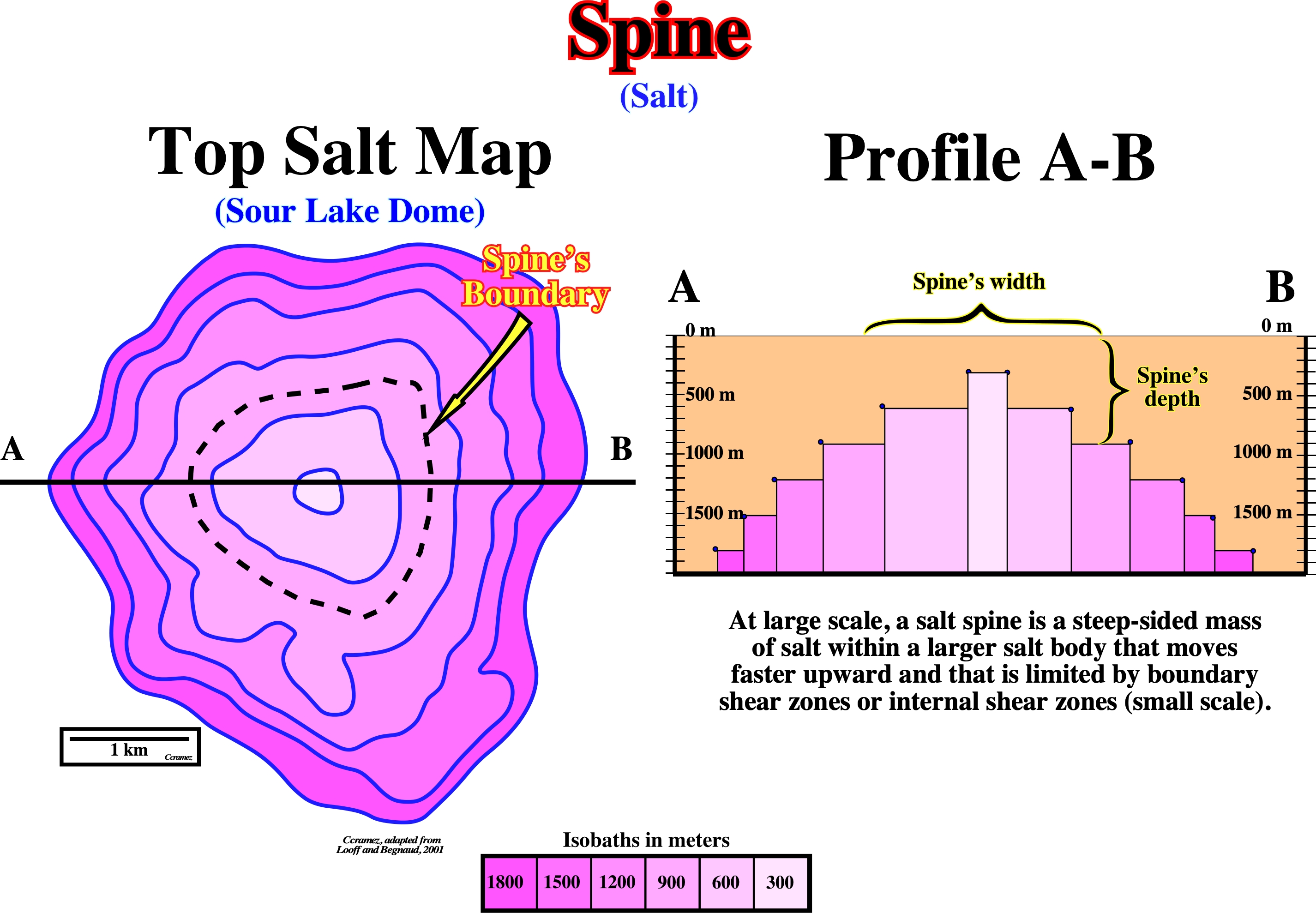
The top of the Sour Lake Dome is here depicted by the isobath map of the top salt and by a the AB profile. The central part of the dome can be interpreted as a salt spine. The spine limit is emphasized by the black dotted line of the top salt. It corresponds to a slight faster upward movement of the salt marked by shear zones recognized on the drilling cores.
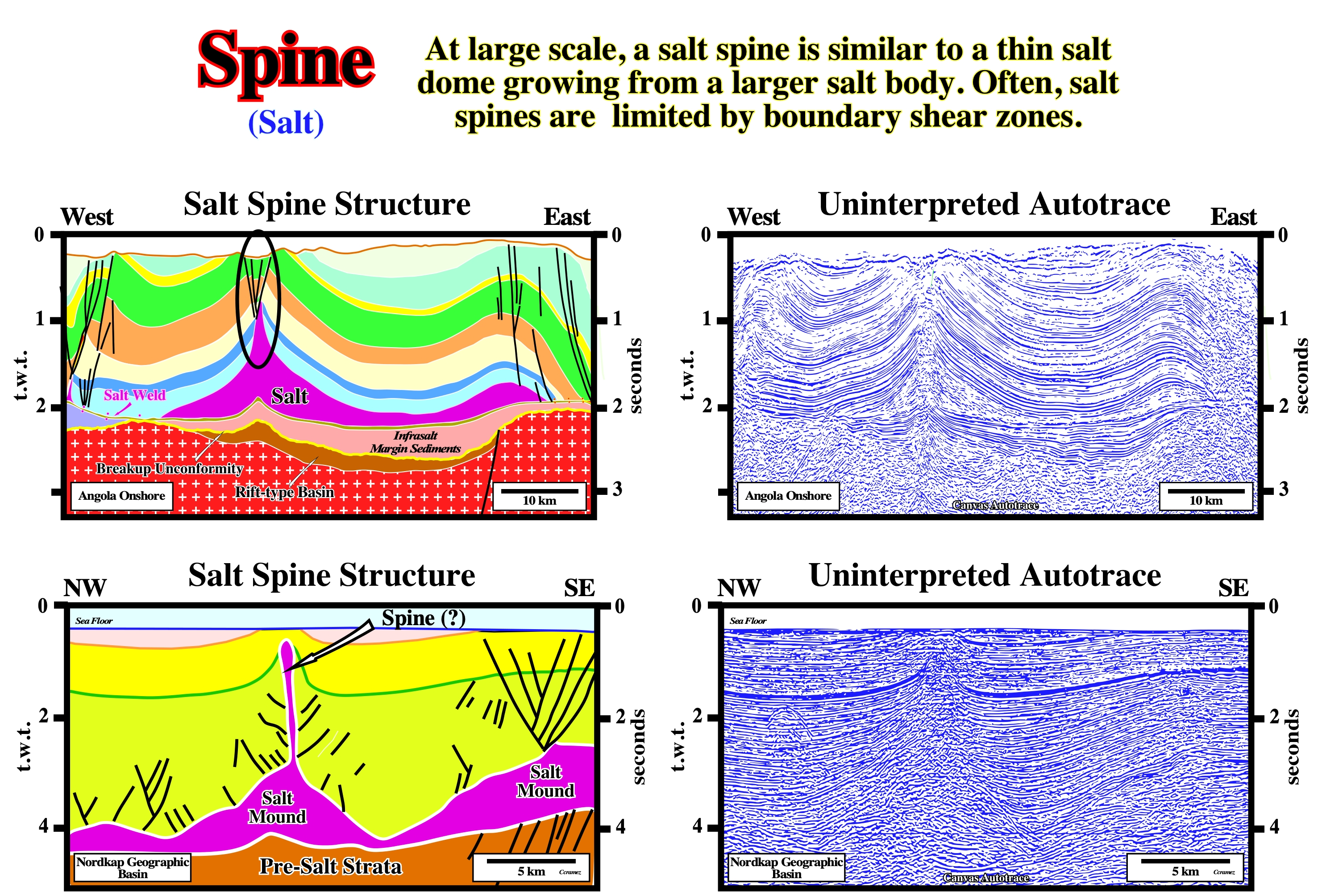
On these tentative geological interpretation of Canvas autotraces (Angola offshore and Nordkapp geographic basin), two likely salt spines are proposed. The geometry of the salt bodies does not seem to falsify the advanced conjecture.
Solution-Transfer Creep
Approximately Newtonian flow occurring in slightly damp salt under typically geologic conditions of low strain and low deviatoric stress under confining pressure. Dynamic recrystallisation occurs when grain boundaries migrate. Grains having high internal strain energy dissolve, liberating ions that diffuse across a thin film of brine and precipitate on a neighbouring grain having low internal strain energy.
![]()
A Newtonian fluid is a fluid in which the viscous stresses arising from its flow, at every point, are linearly correlated to the local strain rate—the rate of change of its deformation over time. Solution-transfert creep occurs in slightly wet salt under geological conditions of weak deformation and weak deviatoric stress under confining pressure.
Spoke Circulation (Talbot and others, 1991)
A second-order cellular pattern of the Rayleigh-Taylor instability similar to that of the most vigorous mode of thermal convention. The pattern is best developed where viscosity contrasts are small. It comprises (i) Downwelling, circular basins and radiating keels of overburden fluid and (ii) Upwelling, circular domes and radiating ridges of buoyant fluid.
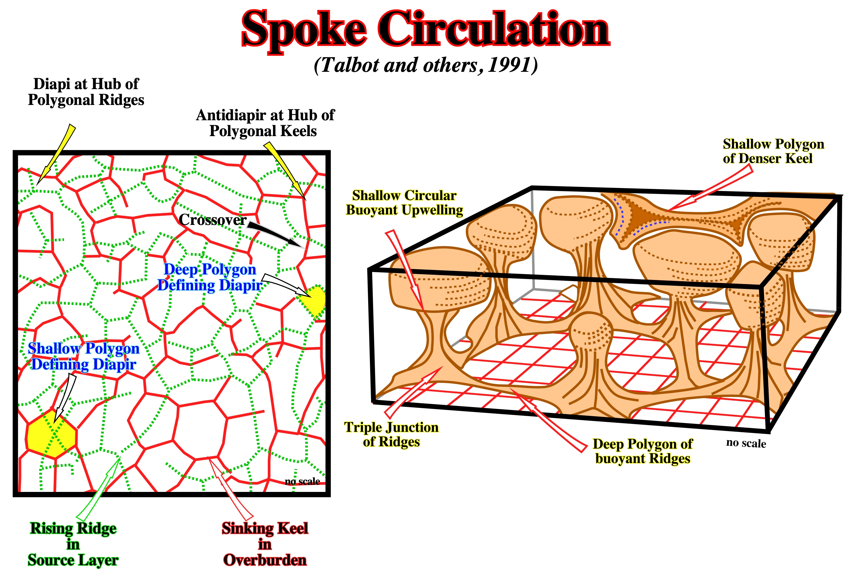
Spoke circulation id the basic pattern of Raleigh-Taylor gravitational overturn of a two-layer system of fluids. In the left is illustrated the spoke pattern in experiment. In the right, a perspective view of a source layer undergoing spoke circulation. The overburden was removed for clarity except for a small piece of one horizon illustrated a sinking keel (Talbot and others, 1991).
Squeezed Diapir
Salt structure and, particularly, diapirs can be squeezed by compressional tectonic regimes as illustrated on the geological tentative interpretation.
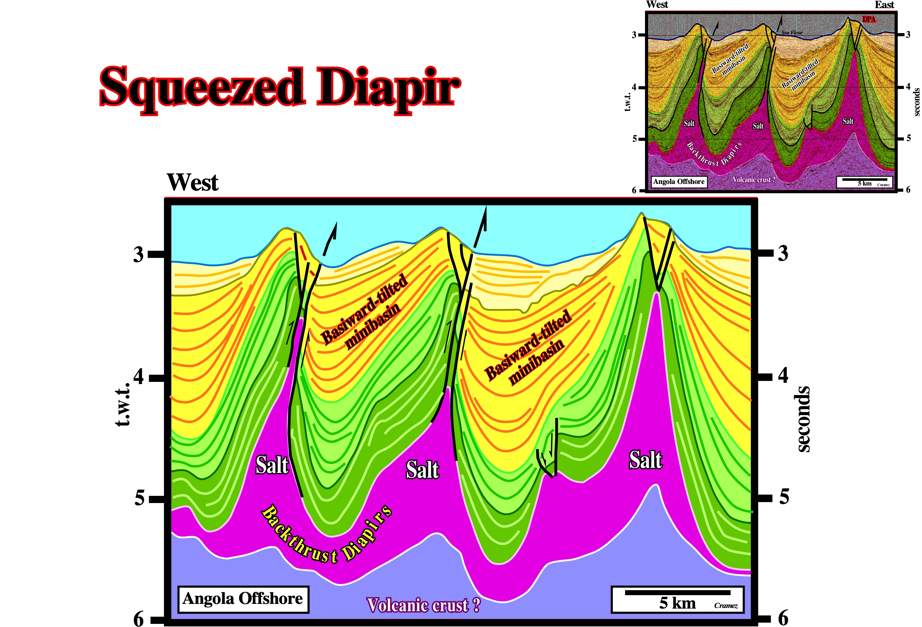
Ridge push forces seem to be responsible of the shortening of the cover in deep water, where salt diapirs have been squeezed and backthrusted, as well as the mini-basins between them. The geometrical relationships between the seismic reflectors (seismic surfaces) and the morphology of the seafloor, strongly, suggest that shortening still is going on. On this tentative geological interpretation of a Canvas autotrace of an Angola offshore seismic line, the basinward-tilted mini-basins are, clearly, visible.
Stem
Comparatively slender part of a salt diapir below the bulb.
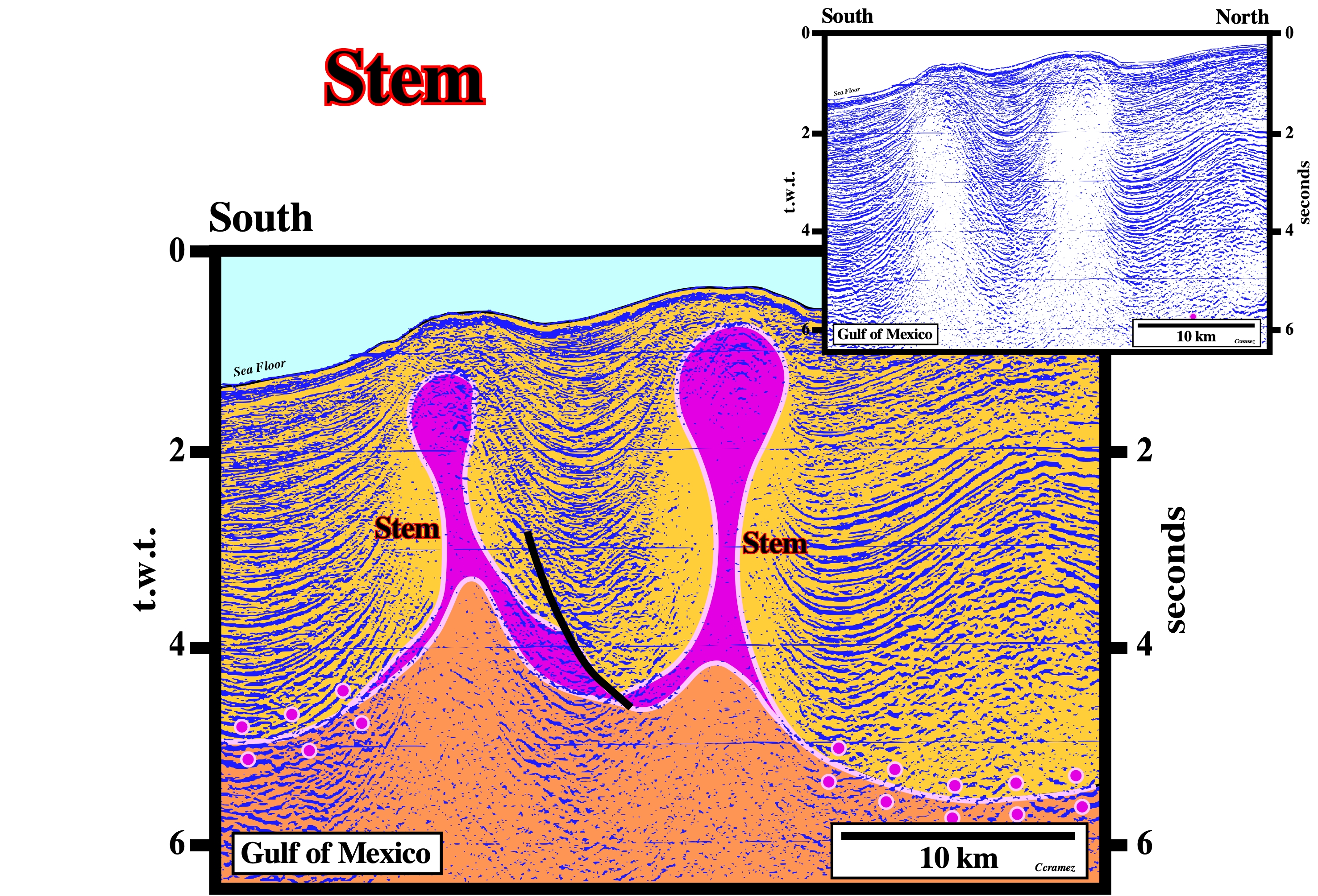
On this preliminary tentative interpretation of a Canvas autotrace of a GOM seismic line, the stems are, relatively, narrow, in circumference, in proportion to the height of the salt diapirs, which are connected of the mother source layer. Primary salt welds can be recognized nearby the salt diapirs.
Stepped Counter Regional System
Synonym of Roho system.
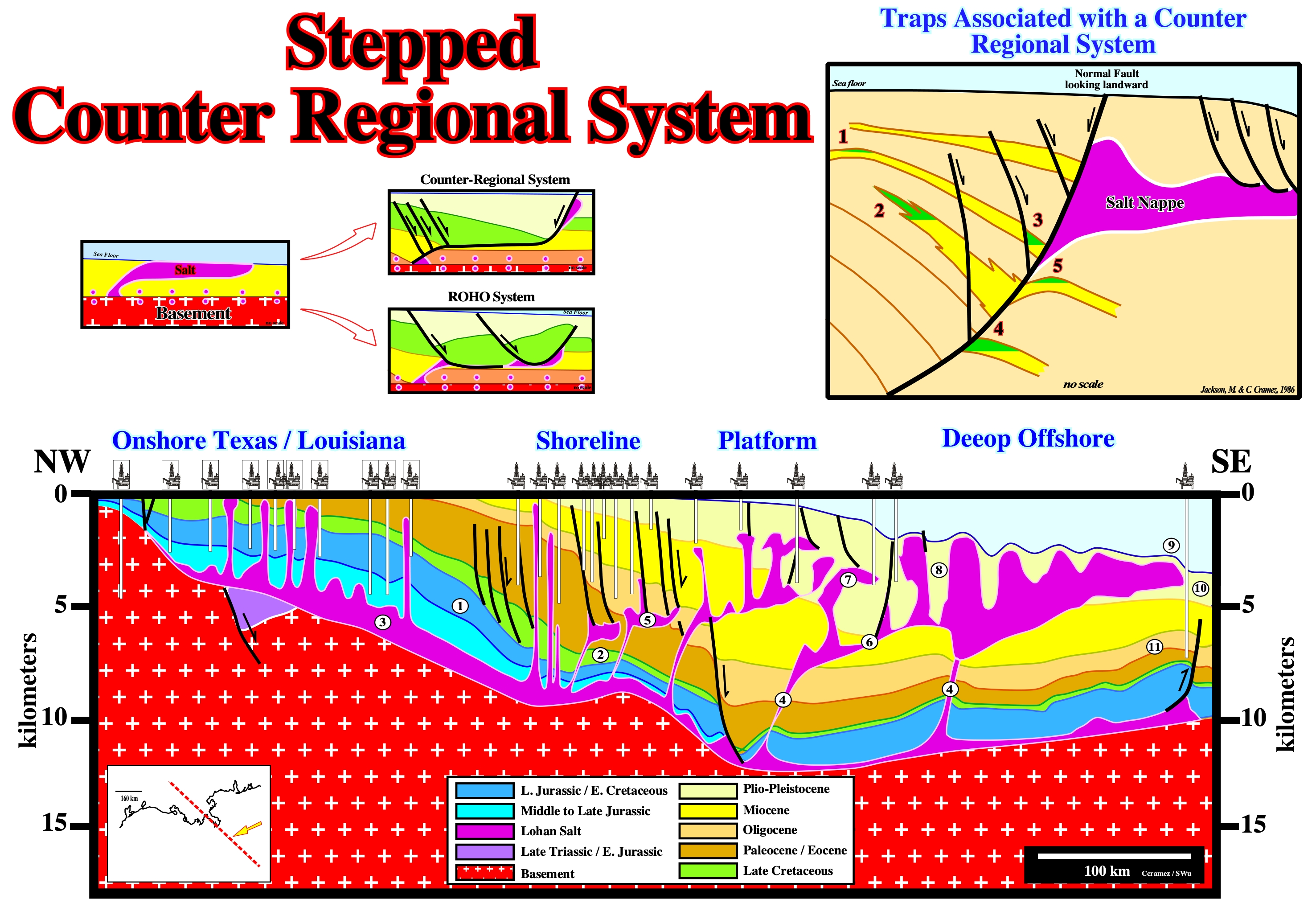
This cross section made in collaboration with S. Wu (1996) illustrates the regional tectonics of the Louan salt and the general stratigraphy of the sedimentary basins composing the Gulf Coast (a Mediterranean-type basin overlain by an Atlantic-type divergent margin). The major geological features of these basins are: 1- The limit “platform / slope” at the Middle Cretaceous ; 2- The sedimentary interval with generating hydrocarbon potential, which, roughly, corresponds to the peak transgression of the post-Pangea continental encroachment stratigraphic cycle (Cenomanian-Turonian) ; 3- The autochthonous salt ; 4- The salt ramps, between the autochthonous and the allochthonous salt layers ; 5- The 1st generation of allochthonous salt ; 6- Salt and fault welds associated with the allochthonous salt ; 7- The 2nd generation of allochthonous salt (it is interesting to notice on this cross-section there are several generations of allochthonous salt, i.e., a salt nappe can be developed from a previous one, which works as a 2nd order mother salt layer) ; 8- The salt expulsion basins upon salt nappes (salt expulsion basins or « mini basins » as labelled by some American geoscientists) ; 9- The Sigsbee escarpment ; 10- The Mississippi deep sea fan : 11- The Perdido fold belt.
Stepwise Centrifuge Model
Using a centrifuge (device intended to impart an acceleration, by means of a rotational movement, to a liquid-solid mixture) M. Jackson (1986) simulated the different steps of salt diapirism and the formation of the allochthonous salt nappes of the Gulf of Mexico.
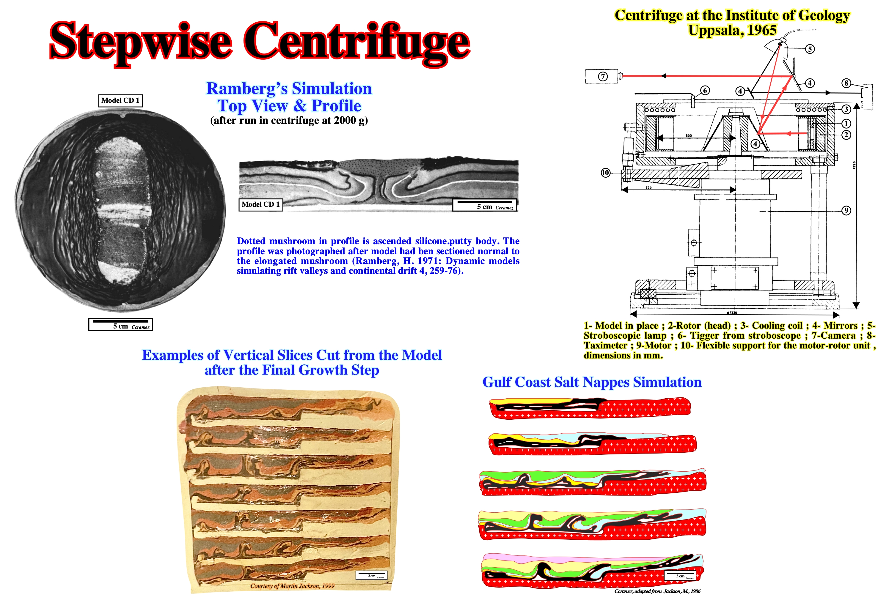
In above M. Jackson's simulation several stages can be considered, one must take into account: 1) The presence of an important step on the infrastructure ; 2) The black layer simulates the salt ; 3) The black layer flows laterally and vertically due to the loading of the yellow layer ; 4) The extension of the yellow layer does not exceed that of the black layer ; 5) The extension of the blue layer, exceeds that of the black layer ; 6) The loading of the blue layer obliges the black layer to flow vertically and slightly rightward ; 7) The depocenters of the green layer not only force the black marker to form intrusive domes, but intrusive nappes as well (they are clearly intruded and cut the blue layer) ; 8) The diapiric mechanism and the allochthony of the black layer continue with the deposition of the upper layers.
Stereographic Projection
A perspective, conformal, azimuthal map projection in which meridians and parallels are projected onto a tangent plane, with the point of projection on the surface of the sphere, diametrically, opposite to the point of tangency of the projection plane. Any point of the tangency may be selected (at a pole, on the equator, or a point in between). It is the only azimuthal projection that is conformal.

Stereographic projections are much used for maps of a hemisphere and are useful in showing geophysical relations (such as patterns of island arcs, mountain arcs, and their associated earthquake epicenters). By the same token, they are used in tectonics and optical mineralogy. They are made on equatorial plane (passing through the center of the sphere) with the point of projection at the south pole.
Strata
Plural of stratum, i.e., a tabular or sheetlike body or a bed, or a layer of sedimentary rock, visually separable from other layers above and below.
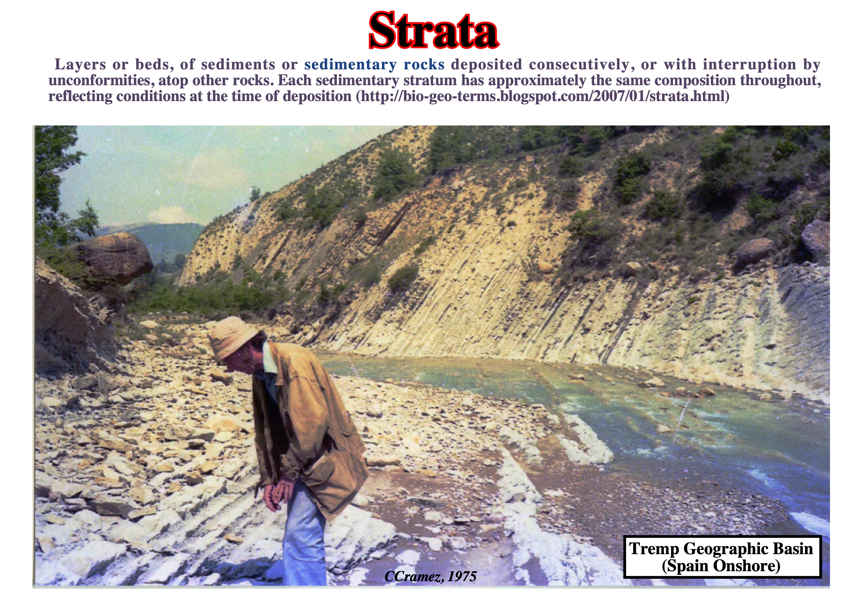
Strata has been defined as the stratigraphic unit that may be composed of a number of beds, as a layer greater than 1 cm in thickness and constituting a part of a bed, and as a general term that includes both bed and lamination. Emiliano Mutti looking to turbidite strata during the 1st field trip he organized for Total SA's geoscientists (CPF's geoscientist at that time, 1975).
Stratigraphic Cycles
Stratigraphic cycle induced by an eustatic cycle. Each hierarchical eustatic cycle induces a correlative stratigraphic cycle. Four types of stratigraphic cycles are, usually, recognized in association with the different orders of eustatic cycles: A) Continental encroachment cycles ; B) Continental encroachment subcycles ; C) Sequence-cycles and D) Parasequence cycles.
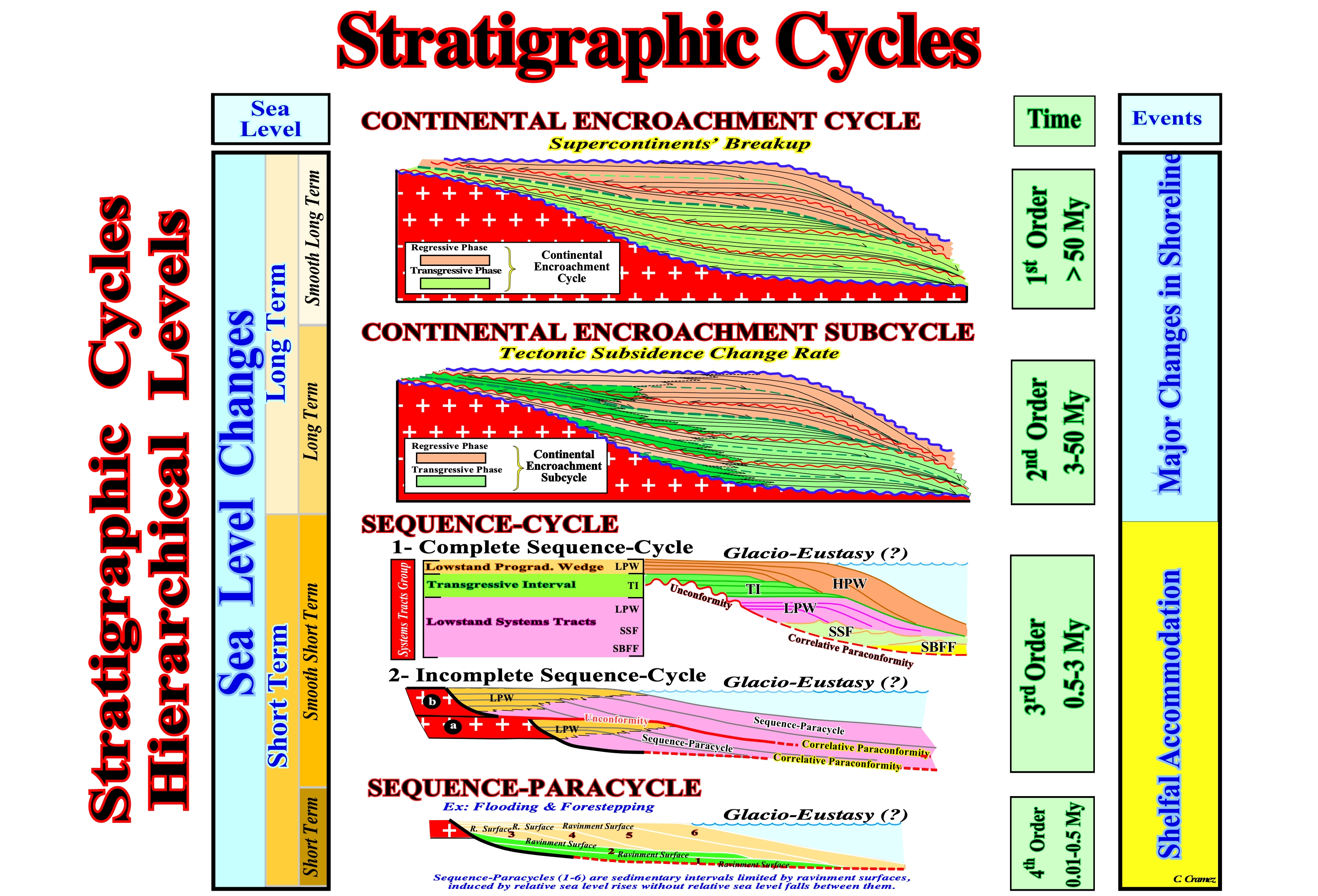
(A) Continental Encroachment Cycles are associated with 1st order eustatic cycles ; they are characterized by a succession of coastal onlap against the cratons ; they fossilize the unconformity created by the aggregation of supercontinents. (B) Continental encroachment subcycles are associated with 2nd order eustatic cycles ; they are characterized by unconformities induced by major basinward shifts of coastal onlap ; the basinward shifts interrupt the continuity of continental encroachment associated with breakup of supercontinents. (C) Sequence-cycles are associated with 3rdorder eustatic cycles ; they are bounded by unconformities induced by changes in water depth, i.e. accommodation in the basin margin ; sequence cycles are bounded by regional onlap surfaces ; systems tracts, i.e. linkage of contemporaneous depositional systems compose sequence cycles. (D) Parasequence cycles are associated with 4th eustatic cycle or higher ; They are bounded by two consecutive flooding surfaces.
Strain Rates (Salt bodies)
The overall change in length per time that can be estimated. The length change is vertical in most salt structures, but its is horizontal for salt sheets, including glaciers.
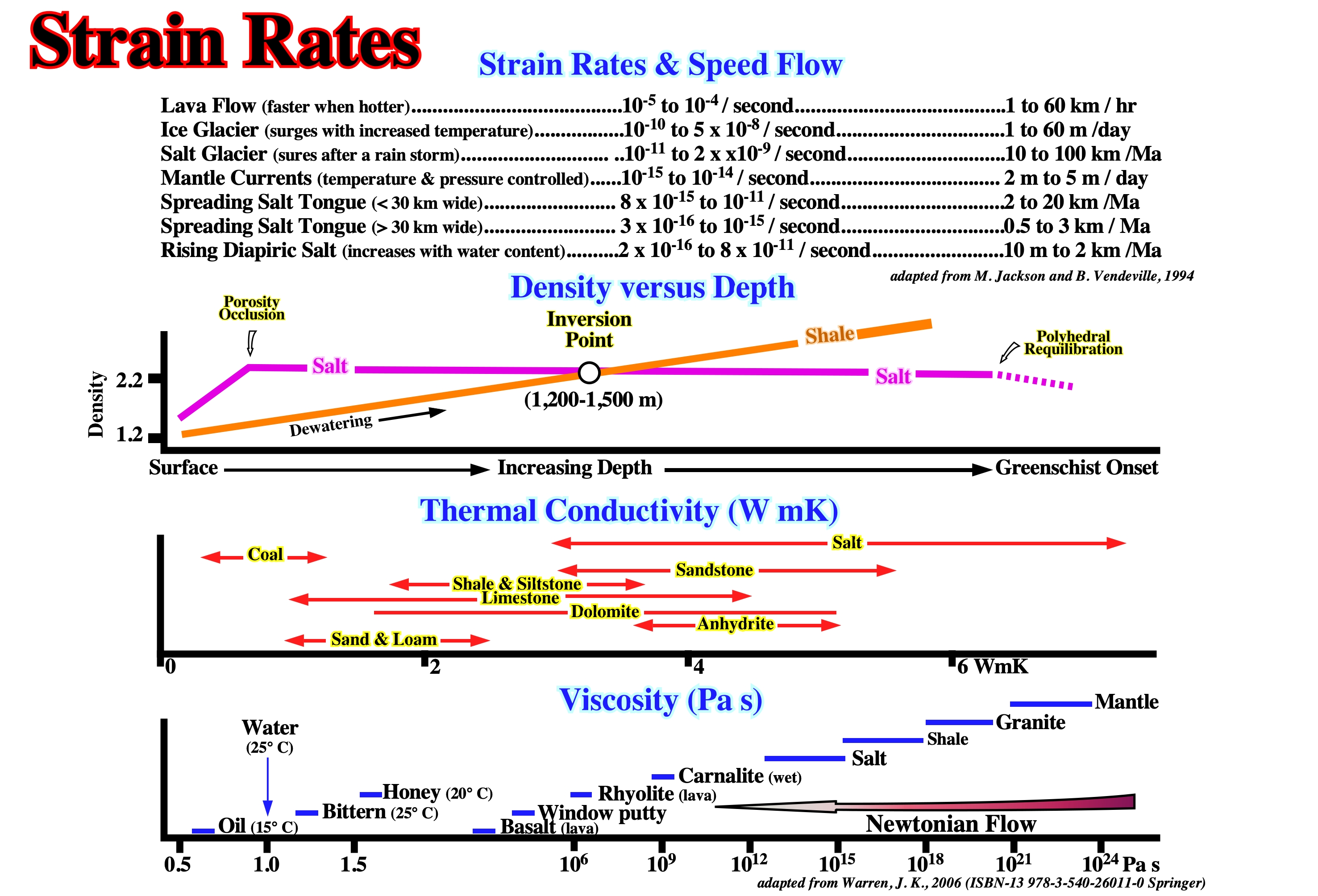
In this plate are summarized : (i) The strain rates and speed flows for different salt structures compared to lava flows and mantle currents ; (ii) Density versus depth for salt and salt, illustrating the inversion point, i.e., the depth at which the density of the sediments becomes higher than the salt density ; (iii) The thermal conductivity for different rock types and (iv) Viscosity, i.e., more or less, the quantity describing a fluid's resistance to flow. The salt properties have been summarized (http://www.files.ethz.ch/structuralgeology/JPB/files/English/12diapirs.pdf) as follows: a) It has a low and almost depth independent density (2.15 to 2.2 g/cm3, depending on the composition ; b) It has a low equivalent viscosity (1018 to 1021 Pa.s) ; c) It is very easily ductile and mobile ; e) It behaves almost like a Newtonian fluid over the geologic time scale ; f) It is a crystalline rock , relatively incompressible.
Streamlines
Laminar flow lines for which the tangent at any point is the local, instantaneous, velocity vector of flow. Decreasing spacing of streamlines indicates increasing velocities of flow and vice versa.
Schematic representation of a laminar and turbulent flow regimes in a pipe displacement simulator. Laminar concentric is in top. Laminar segregated in middle and turbulent in bottom. The turbulent velocity profile represents the mean flow, in which time /space fluctuations are averaged out. The model of Dixon, J. M. is presented in Seyfert C. K., 1987 (Encyclopedia of structural geology and plate tectonics, v. 10, Van Nostrand Reinhold Company Inc. 398-412).
Stress (In a solid)
The force per unit area, acting on any surface within it, and variously expressed as pound or tons per square inch, or dynes or kilograms per square centimetre; also, by extension, the external pressure which creates the interval force. The stress at any point is mathematically defined by nine values: three to specify the normal components and six to specify the shear components, relative to three mutually perpendicular reference axes.
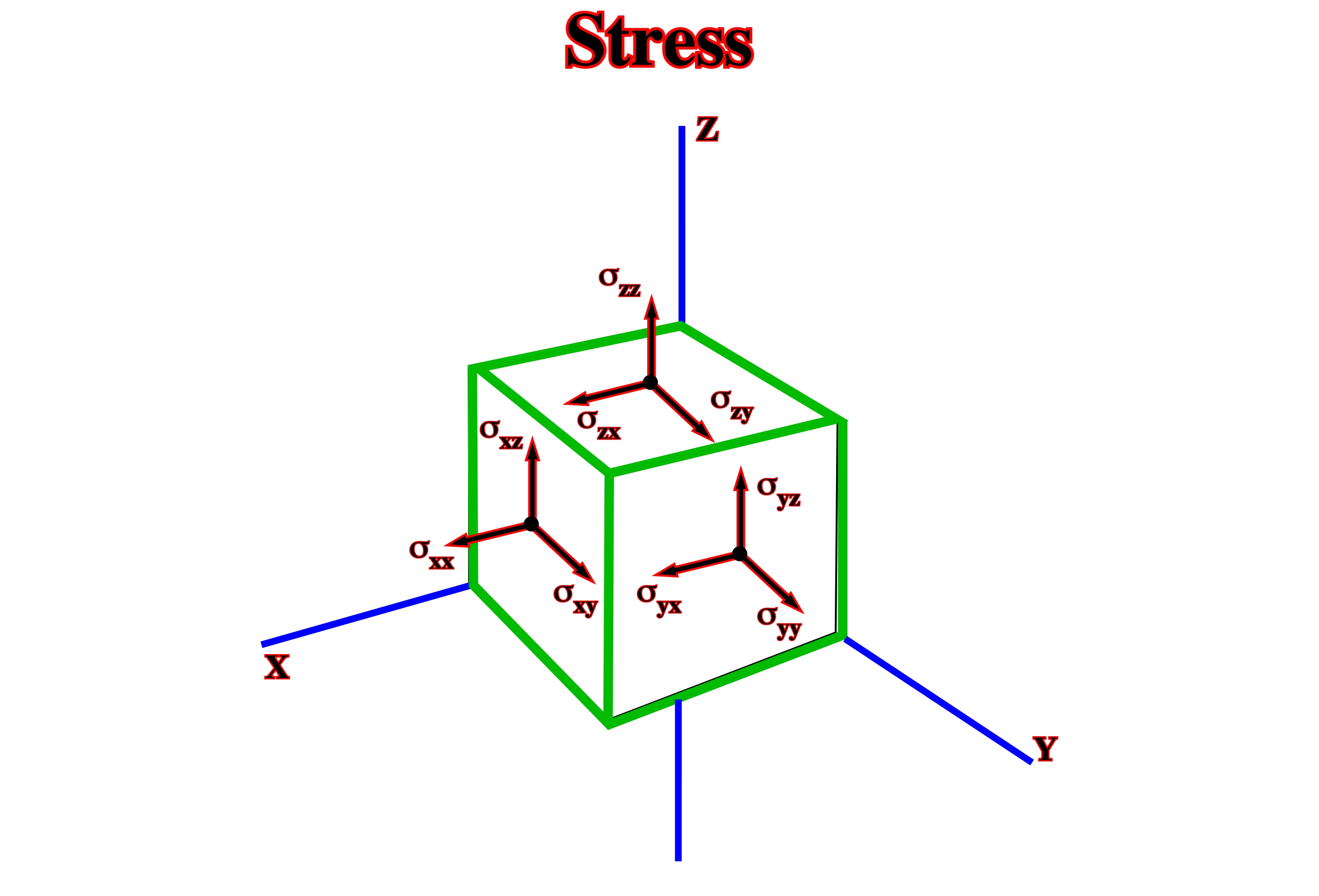
Stress is a tensor (designates a very general object, whose value is expressed in a vector space) of second rank* . The forces are thought to act on every one of the infinitersimal elements of area with different orientation, which can be imagined at one point. Only such forces are considered, which are locally in equilibrium with equal and opposite forces: tensort is symmetrical.
* Many properties are tensors that relate one vector to another or relate a scalar to a tensor. If the driving force and the response are collinear the property can be expressed as a scalar, but when that are not, the property must be expressed as a second rank tensor.
Stretching Faults
Normal faults associated with diapiric structures in order to extend the overlying sediments to respect the Goguel's law (volume problem). Stretching faults are often used as a synonym of radial faults.
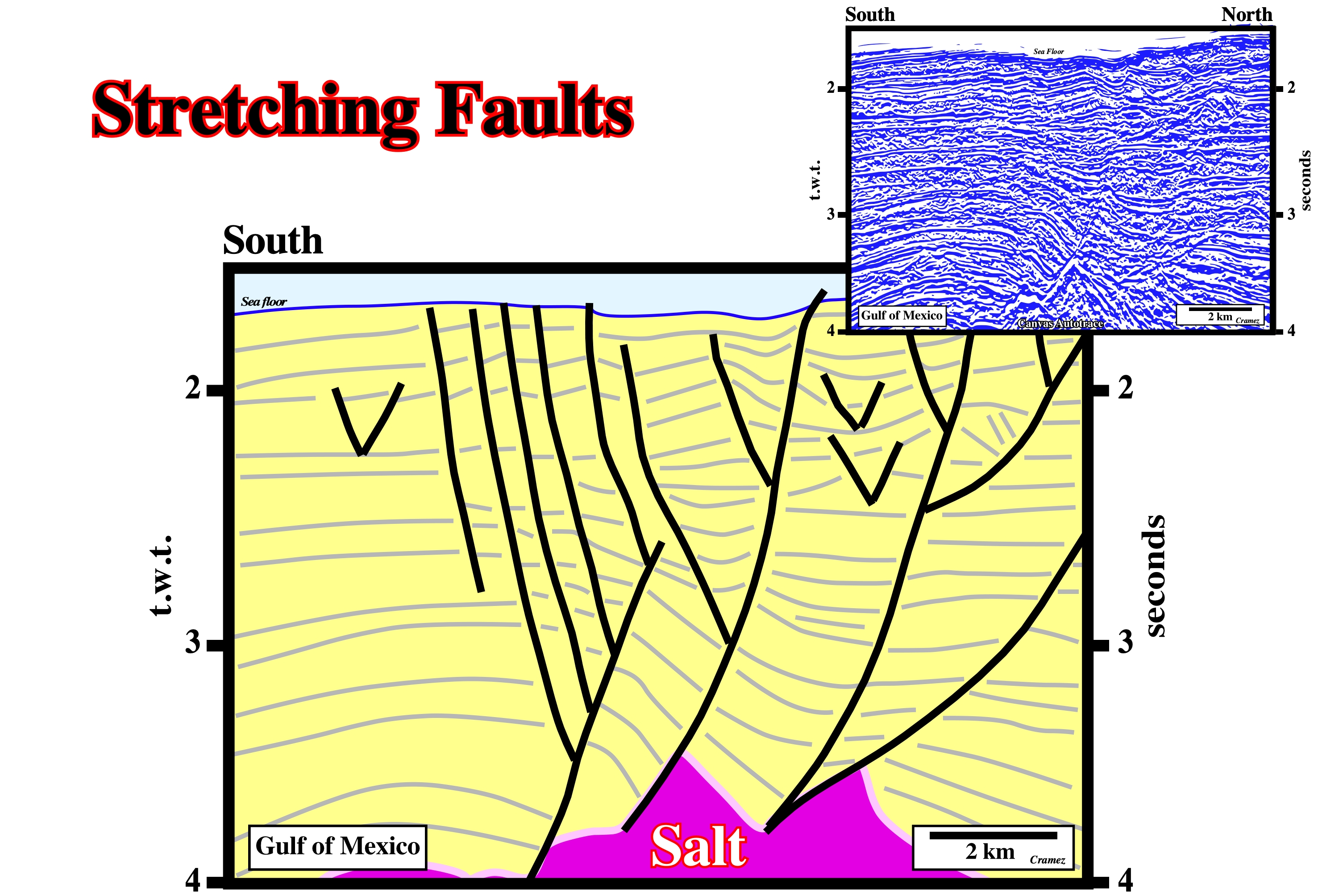
Stretching faults strike in all directions. They are induced by local extensional tectonic regimes, in which σ2 and σ3 are equal. As they elongate the sediments to accommodate them to new volume conditions. On seismic lines or in their Canvas autotraces, the stretching faults have opposite vergences. Theoretically, the sum of throws with opposite vergence must be zero.
Strike-Slip Movement
Movement parallel to the strike of a fault.
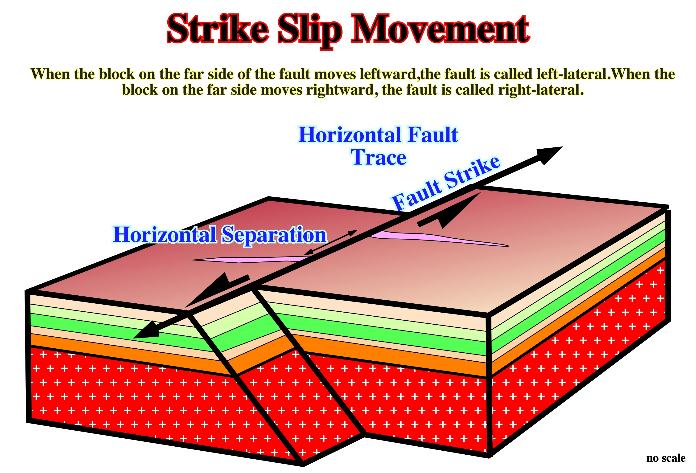
A strike-slip movement can take place in normal, reverse or strike-slip faults. The picture above represents a strike slip movement component of normal or reverse fault, since the fault plane has a no vertical dip. Geoscientists should not forget that a strike slip faults have high dips, often almost vertical. A strike slip movement is not a mechanism to lengthen (normal faulting) or shorten (reverse faulting and folding) the sediments.
Structural Inversion
Reversal of vertical motion recorded by stratigraphic thickening or thinning of synkinematic strata.
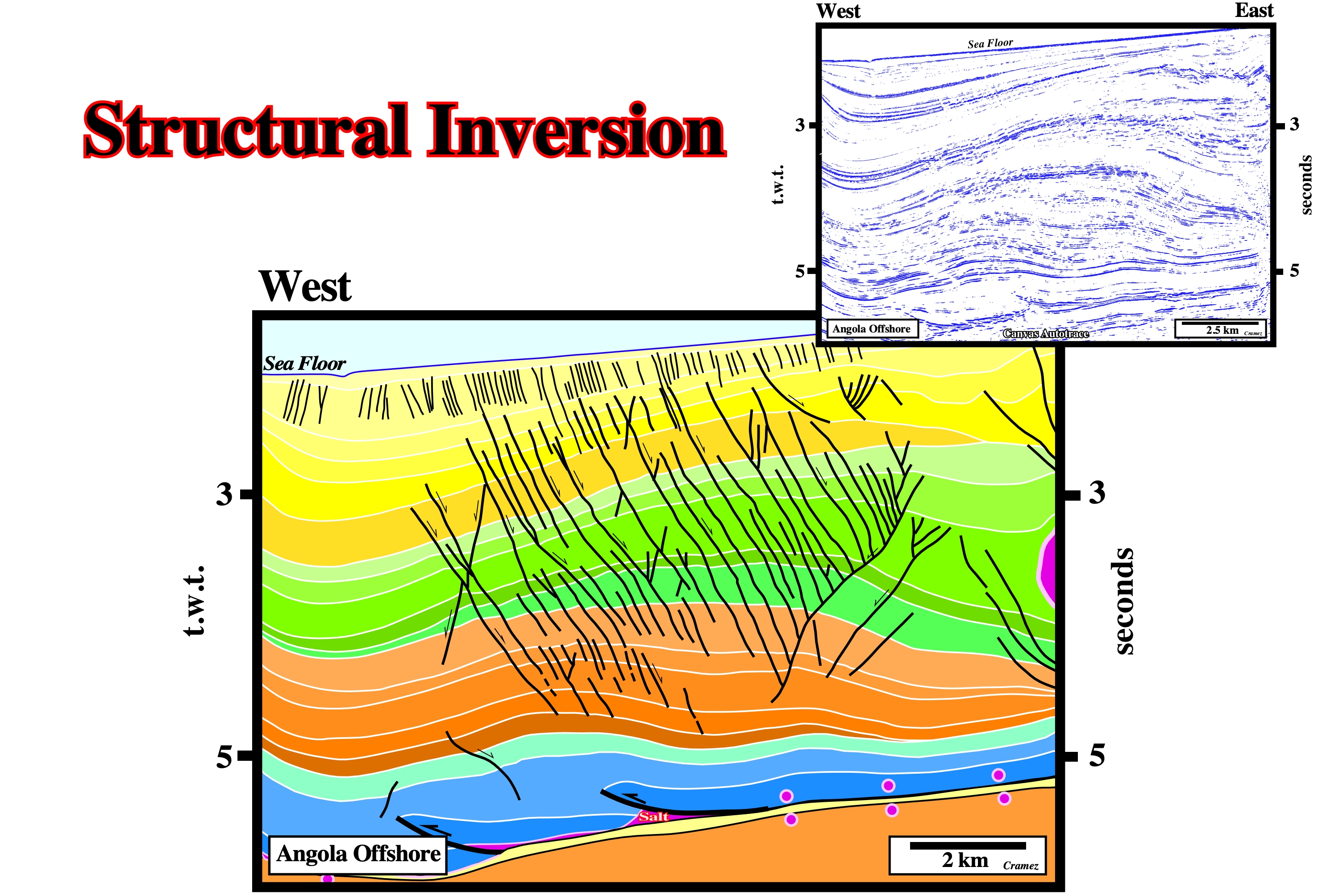
Structural inversions and, particularly, salt induced tectonic inversion, as the one illustrated on this tentative interpretation of Canvas autotrace of an Angola offshore seismic line, imply lengthening of the upper sedimentary layers. Therefore, a coeval normal faulting systems is associated. The presence or absence of coeval normal faults, near the apex of domatic structures, can be used to differentiate antiforms, created by salt-induced inversions from anticline structures created by a compressional tectonic regime. There is, also, tectonic inversions created by compressional tectonic regimes. Indeed, quite often, the normal faults bordering the halfgrabens of the rift-type basins under a compressional tectonic regime are reactivated as reverse faults shortening the sediments of the hangingwall creating anticline structures (no coeval normal faults on the apex of the structures).
Subrosion
When a salt dome is not outcropping but covered by a relative thin and permeable sedimentary interval, the roof of the dome can be washed.
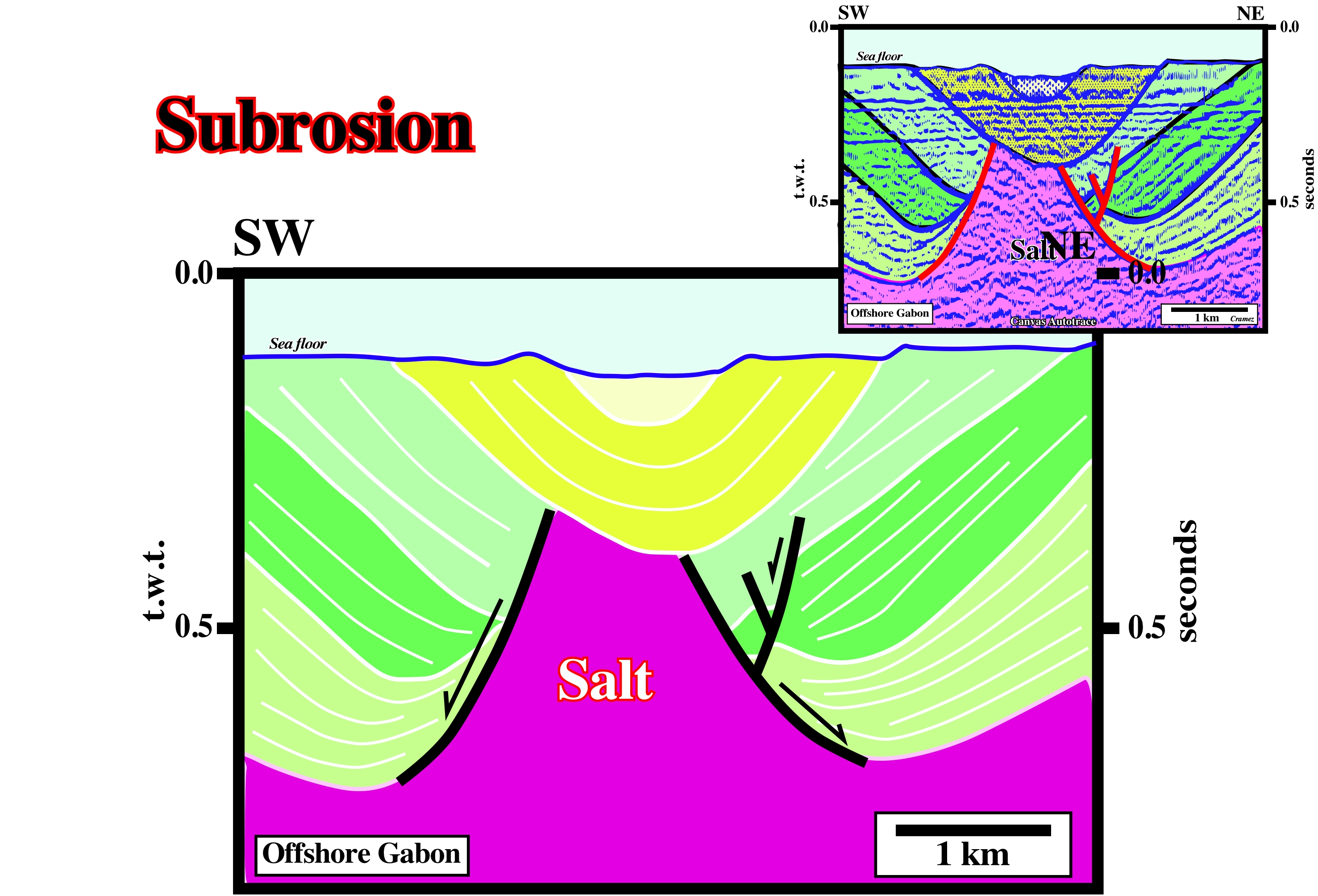
The depocenter above the salt dome can be explained as a consequence of a salt collapse following the subsurface erosion due to salt dissolution.
Subsalt Strata
Sedimentary package underlying a salt layer or a salt weld.
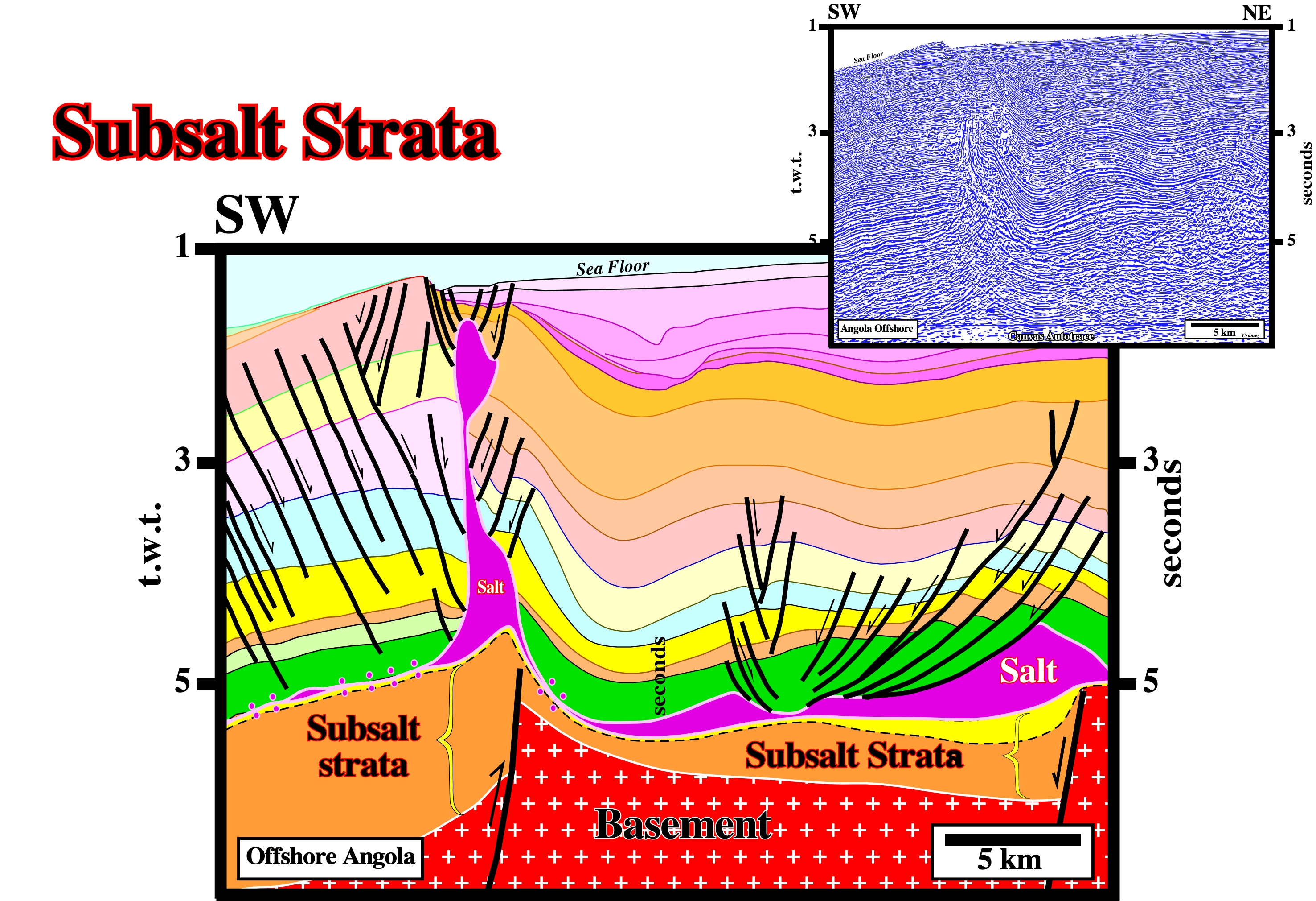
On this tentative geological interpretations of a Canvas autotrace of a seismic line, sub-salt strata is composed by the basal Cretaceous sandstone of the margin (in yellow) and rift-type basin sediments (in brown). The infrastructure of the subsalt strata is the Precambrian basement.
Subsidence (McNeill, L. et al., 1999)
A sudden sinking or gradual downward settling of the Earth's surface with little or no horizontal motion. The movement is not restricted in rate, magnitude, or area involved. Subsidence may be caused by natural geologic processes, such solution (karsts phenomena), thawing, compaction, slow crustal warping, or withdrawal of fluid lava from beneath a solid crust. See: Compensatory subsidence.
In the history of sinking (lowering of an area of land in relation to the surrounding land), it is necessary to differentiate the total subsidence (thickness of sediments plus water-depth) of tectonic subsidence. The tectonic subsidence is equal to the reduced total subsidence of the isostatic compensation effect (due to sedimentary overload) and increased compaction effect. The diagenetic compaction can be presented under two aspects: (a) Chemical and (b) Mechanical. Chemical compaction encompasses the dissolution of minerals under pressure, whereas mechanical compaction does not encompass chemical processes, but physical aspects such as change in intergranular packing and deformation or breaking of individual grains. The tectonic subsidence can reach about 40% of the total subsidence. As illustrated in this figure, Greenlee (1989) calculated on the USA eastern continental margin, using the results of the COST B-2 (drilled in New Jersey offshore) and the stratigraphic data deduced from the seismic lines, the fluctuations of relative sea level change ; (ii) The tectonic subsidence ; (iii) Total subsidence; (iv) Paleobathymetry (bathymetry of the marine environment which the deposition of a given lithological unit, which characterizes a moment of geological history in which it occurred) ; (v) The long term eustatic curve (curve of the absolute or eustatic sea level changes *), and proposed the most probable mechanisms of subsidence. After the breakup of the lithosphere of the Pangea supercontinent, Greenlee admitted three cycles of thermal cooling. In the first two, it conjectured a slow Atlantic opening, which then accelerated as sedimentary transgression/sedimentary regression cycles**, more or less, contemporaneous with an important volcanic event, were deposited. The calculation of subsidence and paleobathymetry were corroborated by more recent data. The evolution of geological events seems to have not withstood recent refutation tests. The volcanic event (hot spot, i.e., a thermal anomaly inside the Earth, associated with mantle convection systems responsible for volcanism occurring within tectonic plates) is underlined by sub-aerial lavas (SDRs) (more or less 179.5 Ma), and which fossilized, locally, the rift-type basins that formed during the rifting phase in which subsidence was differential. The first opening phase of the Atlantic was sub-aerial, by lateral deposition of the lavas from the expansion centers, and only later, when the expansion centers sank (ocean crust formation) and the opening became oceanic oceanic) and thermal subsidence. All these conjectures were, perfectly, corroborated by the recent drilling wells in the US Atlantic offshore. On the tentative geological interpretation of a Canvas autotrace of a Vietnam offshore seismic line, illustrated in this figure, the differential subsidence, during lengthening or rifting from an internal backarc basin, is obvious. In the non-Atlantic-type divergent margin, which fossilizes the backarc basin, subsidence is thermal, as in the divergent margin of the East of the United States studied by Greenlee, and seems to be the result of the cooling of the thermal anomaly that caused the lengthening of the lithosphere (differential subsidence). As no normal faults of the backarc basin affects the divergent margin (Vietnam offshore), many geoscientists suggest that since the differential subsidence (thermal anomaly, i.e., isotherm rise) stops, thermal subsidence (isothermal descent) begins. the result of a cooling and not a heating.
(*) The absolute sea level is the result of the combination of: i) Tectono-Eustasy that is controlled by the volume variation of the ocean basins in association with oceanic expansion following the rupture of the supercontinents ; (ii) Glacio-Eustasy, which is controlled by the variation of water volume of the oceans as a function of the amount of ice (assuming that the amount of water in all its forms is constant since the formation of the Earth, around 4.5 Ga) ; (iii) Geoidal-Eustasy, which is controlled by the distribution of ocean water caused by variations in the Earth's gravity field (where gravity is stronger than normal, sea level is thrown to the center of the Earth) and (iv) Steric seas level rise or thermal expansion of the oceans (if the temperature increases, the density of the water decreases, and for a constant mass, the volume increases).
(**) Many geoscientists say transgressions/regressions cycle, forgetting that the term transgression, above all, refers to the advance of the sea on the continent, that is to say, to a marine ingression. Therefore a geoscientist should always say cycles of sedimentary transgressions/sedimentary regressions when he is referring to the cycles of the retrogradational and progradational intervals, which are separated by a downlap surface.
Substratum
An underlying layer. However, in salt tectonics, certain geoscientists use the term substratum to designate the ductile layer below a brittle overburden and above the subsalt strata or basement, i.e., to designate the salt layer. Substratum is a term more general than source layer. The substratum may or may not give rise to upwelling structures.
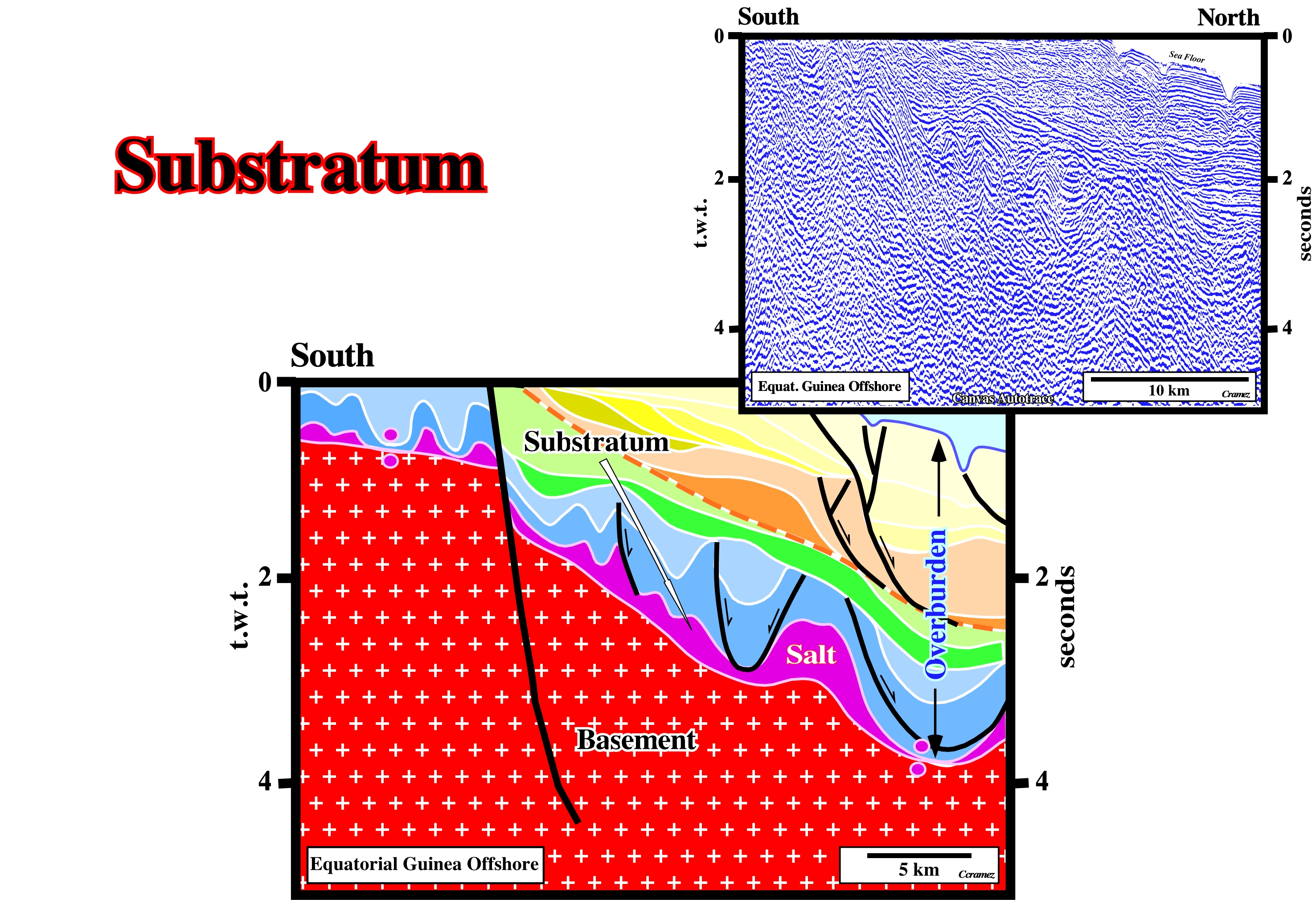
Generally, in a continental divergent margin, with a significant salt layer, as the one illustrated on this tentative interpretation of a Canvas autotrace of an Equatorial Guinea offshore seismic line , the substratum is formed by the autochthonous salt layer, which, often, overly either (i) subsalt margin sediments, (ii) rift-type basin sediments, (iii) Paleozoic fold belt or a (iv) Precambrian basement. On this particular example, in which the subsalt margin sediments are under seismic resolution, the substratum (salt) seems to overlie, directly, the Precambrian basement.
Sylvite
A white or colorless isometric mineral: KCl. It is the principal ore mineral of potassium compounds. Sylvite occurs in beds as a saline residue with halite and other evaporites. It has a sharper taste than of halite. It forms crystals in the isometric system very similar to normal rock salt, halite (NaCl). The two are, in fact, isomorphous. Sylvite is colorless to white with shades of yellow and red due to inclusions. It has a Mohs hardness of 2.5 and a specific grvity of 1.99. It has a refractive index of 1.4903. Sylvite has a salty taste with a distinct bitterness.
Philippe-Crochet, in its site (https://www.philippe-crochet.com/galerie/desert/details/209/iran-fevrier-2016-domes-de-sel) gives nice examples examples of salt domes with layers of sylvite in Southern Iran. The salt in depth rises to the surface by halokinesis. In fact, evaporites and particularly the salt have low density and ductility (property of deforming without breaking) compared to the host rocks. The rise of the salt can be stopped before reaching the surface (intrusive dome) or pierce the latter (extrusive dome). In the second case, true mountains of pure salt are formed which are subject to erosion. As the can be dissolved in water, the rain will shape specific and spooky landscapes, with in particular sharp and very hard edges making the progression delicate. Dissolution can create significant The main mineral in these domes is halite, which is, generally, white or gray depending on the impurities it contains. However the presence of other minerals as sylvite (potassium) gives a colour a ranging from orange-pink to red, while the carnalite (magnesium) gives to the salt other couloirs. The large photo photo has taken on the Dashiki dome in south-eastern Iran, not far from the town of Khormoj (Boshehr Province) in the Zagros Mountains.
Syndepositional
Conteporaneous of the sedimentation.
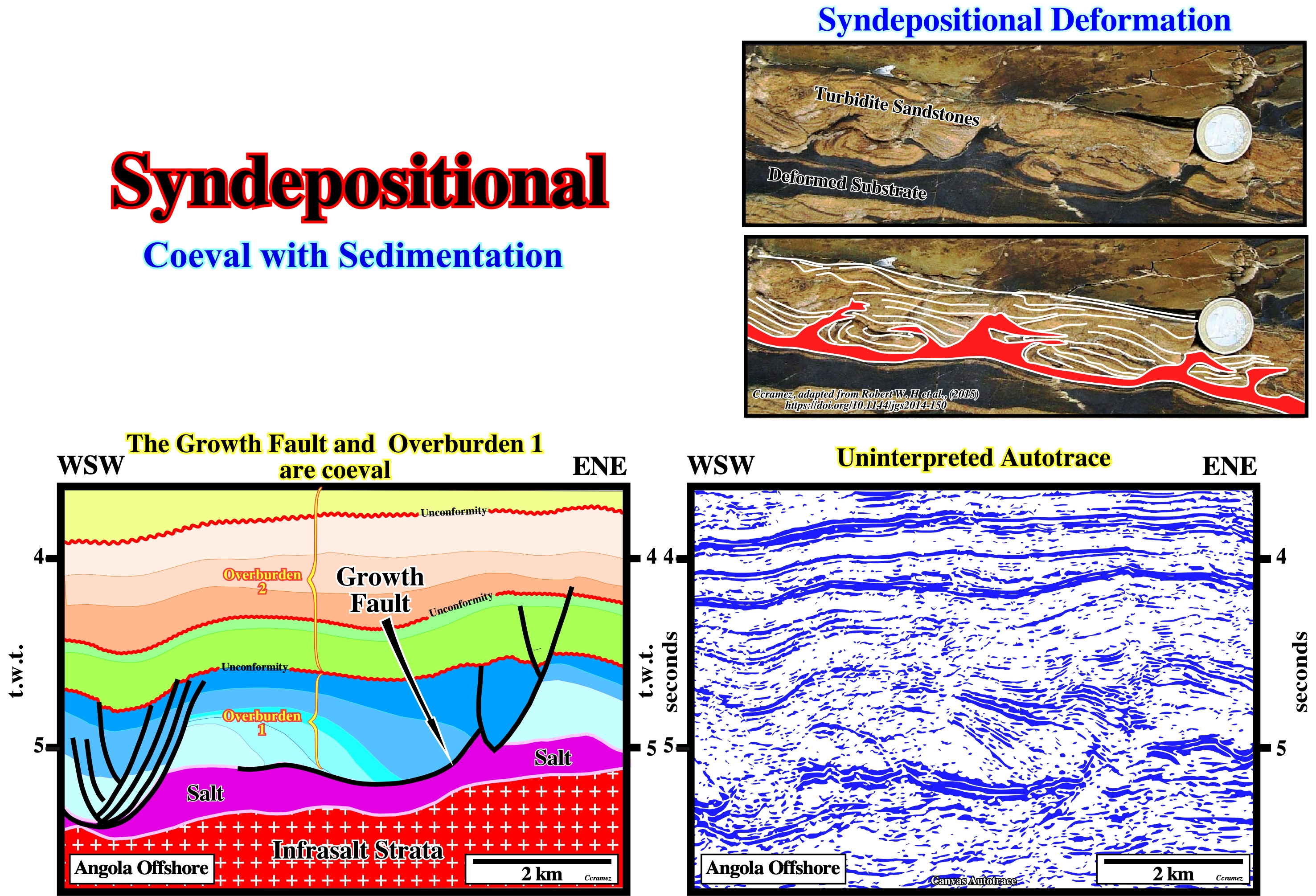
Turbidite sandstones and related deposits, often, contain deformation structures and remobilized sediment that might have resulted from post-depositional modification such as downslope creep (e.g. slumping) or density-driven loading by overlying deposits. However, some deformations can occur during the passage of turbidity currents that exerted shear stress on their substrates (whether entirely pre-existing strata, sediment deposited by earlier parts of the flow itself or some combination of these). Butler, Robert W et Al (2016), advanced criteria to avoid confusion with products of other mechanisms (e.g. slumping or later tectonics), which establish the synchronicity between the passage of overriding flows and deformation of their substrates. This underpins a new analytical framework for tracking the relationship between deformation, deposition and the transit of the causal turbidity current, through the concept of kinematic boundary layers. The case illustrated above, drawn from Miocene outcrop of New Zealand shows asymmetric flame structures, convolute lamination, some debritic units and injection complexes, together with slurry and mixed slurry facies. . On the tentative geological interpretation of a Canvas autotrace of an Angola seismic line, Cretaceous sediments and particularly those of the Pinda formation (in blue colours), which is a potential reservoir interval, were extended by growth-faults developed on the top of the salt layer due to an synsedimentary extensional tectonic regime characterised by σ1 vertical, σ2 horizontal striking more or less N-S and σ3 horizontal and perpendicular to σ2 , i.e., striking W-E.
Synform
Foldlike geometry whose limbs close downward. Conventionally a synform is not the consequence of a shortening as it is the case for a syncline. See:Antiform.
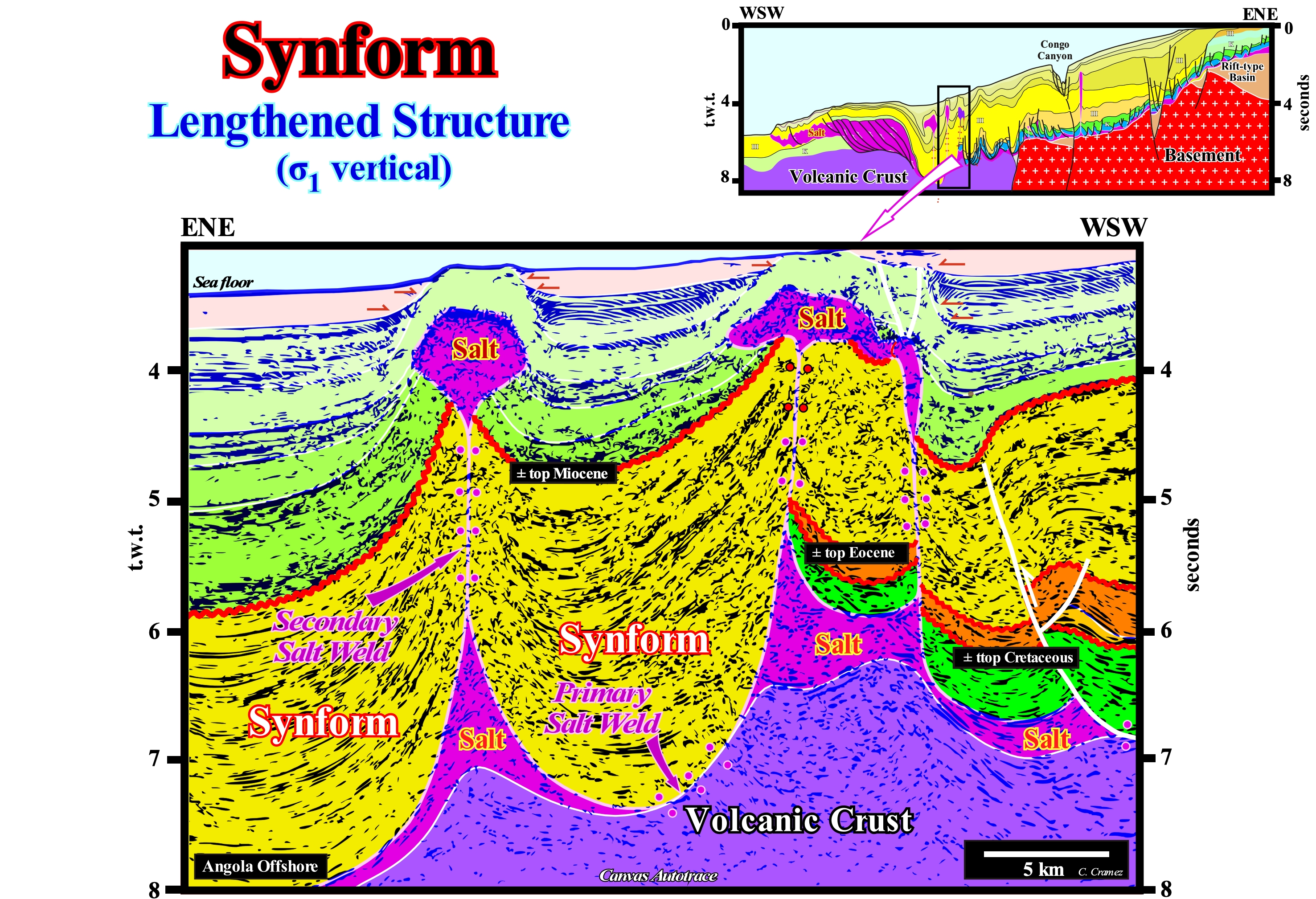
Angola offshore and particularly the northern offshore corresponds to the stacking of several basins of the classification of the sedimentary basins of Bally and Snelson (1980). On regional seismic lines it is easy to recognize, from the bottom to top: (i) A basement that often corresponds to a Paleozoic flattened mountain belt ; (ii) Late Jurassic / Early Cretaceous rift-type basins, which lengthened the lithosphere of the small supercontinent Gondwana before its breakup ; (iii) Atlantic-type margin divergent, whose sedimentary column can be divided into two large sedimentary phases: (i) Transgressive phase with a globally retrogradational geometry and (ii) Regressive phase, which fossilizes the transgressive phase and exhibits a progradational geometry. Some geoscientists, taking into account the important deposition of a salt layer (evaporites) in the divergent margin, consider two large sedimentary intervals: a) Infrasalt interval and b) Suprasalt interval. These two intervals are, easily, recognized on the seismic data, since the presence of the salt interval creates a salt induced tectonic disharmony. The sediments of the suprasalt interval are deformed by halokinesis and rafting tectonics (induced by gravity and salt), whereas the infrasalt sediments are, more or less, undeformed. On this tentative geological interpretation of a Canvas auto-trace of a detail of a seismic line of this offshore, it is, easy, to verify that synform structures are associated with the halokinesis (salt tectonics without tectonic vector). They formed as the salt flowed sideways and vertically. When the salt flows, the flow creates a void, which is filled by the already deposited sediments or by synchronous sediments of the flow. As many geoscientists say, nature has a horror of emptiness. The filling of the empty space is done by lengthening the overlying sediment which can only be done by normal faulting. Most of the time, as is the case on this tentative, normal faults are not visible because their jumps are very small and inferior to the seismic resolution. However, these normal faults are, perfectly, visible in dipmeters logs and, above all, in drilling cores. It is important to note that in this particular auto-trace the geometry of the synforms was, later, slightly deformed, since during the Pliocene the sediments were shortened by a compressional tectonic regime (constraint by the ocean ridges), as onlapping, in the upper part of the tentative interpretation (above the salt bulbs), suggests. This deformation has nothing to do with the uplift (lengthening and non-shortening) that the proximal part of this offshore suffered during the Late Tertiary. It is quite visible on the tentative interpretation, shown in the upper right corner of this figure. Constraint** by the mid-oceanic ridges contributed to the formation of vertical salt sutures (2nd order sutures), which separate allochthonous from autochthonous salt, although the main mechanism was the difference in density between salt and sediment. Sediments compact as they are buried increasing their density. The salt does not compact. The density of the salt is, more or less, constant in depth (2.15 / 2.17 as a function of the magnesium content). A salt dome with vertical walls (cylindrical geometry) is a physical impossibility. There is a level of inversion, above which the salt is denser than the sediments. Above this point (inversion point), the salt exerts a pressure against the sediments which is not compensated by the pressure that the sediments exert against the salt. Underneath the inversion point, it is the opposite, the pressure that the sediments exert against the salt is not compensated by the pressure that the salt exerts against the sediments and for that reason the salt flows forming a salt structure with the geometry of a drop structure. The disconnection of the salt drop (allochthonous salt) may be total or not of the source salt rock (not to be confused with the oil source rock) that is the autochthonous salt horizon.
(*) The brine of the evaporites was enriched in potassium by the presence of subaerial lavas, deposited, immediately, after the break-up of the lithosphere, in the sea floor. Indeed, the spilitisation of the basalt of sub-aerial volcanism is, probably, the origin of the formation of the potassium rich and poor MgSO4 that constitute the salt interval Angola offshore.
(**) Constraint by oceanic ridges and descending lithosphere plates are informal terms used in the literature of Plate Tectonics. These expressions designate the associated horizontal forces: (i) The horizontal compression resulting from the differences in elevation between the oceanic expansion centre and the ocean floor, and (ii) The tensile effects of an oceanic lithosphere plate originating from the downward movement along a subduction zone of Benioff (B-type subduction).
Synkinematic Layer
Strata interval, typically overlying the prekinematic layer, showing local stratigraphic thickening (above structures such as withdrawal basins that subside faster tan their surroundings) or thinning (above relatively rising structures). Changes in thickness can also be recorded by onlap or truncation at all levels of the synkinematic layer.
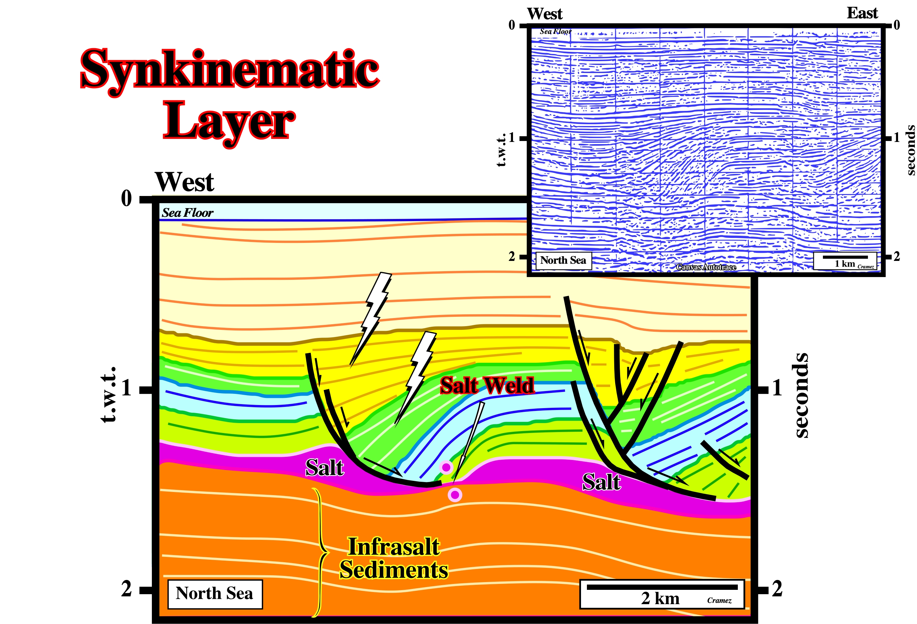
The synkinematic layers, as those illustrated above, thickening toward the growth-faults. They record sedimentation during salt flow or during any other type of deformation. The light green and blue intervals are prekinematic, which are roughly isopachous. The upper green and yellow interval are synkinematic. Their internal configuration is divergent against the growth fault planes suggesting the compensatory subsidence increases toward the fault.