
Calcite (American Geological Institute, 1999)
A common rock-forming mineral: CaCO3. It is trimorphous with aragonite and vaterite. Calcite is, usually, white, colorless, or pale shades of gray, yellow and blue. It has a perfect rhombohedral cleavage, vitreous luster and a hardness of 3 on the Mohs scale. It readily effervesces in cold dilute hydrochloric acid. It is the principal constituent of limestone. Calcite, also, occurs in crystalline in marble, loose and earthly in chalk, spongy tufa (variety of limestone formed when carbonate minerals precipitate out of ambient temperature water) and stalactitic in cave deposits. It is common found as gangue mineral in many ore deposits and as cementing medium in clastic sedimentary rocks.

Calcite is also a minor constituent of many igneous rocks and the chief constituent of some carbonatites. Calcite crystallizes in a variety of forms, such as nailhead spar, dogtooth spar and Iceland spar. Calcite can form as a result of geochemical processes of an inorganic or biotic nature when the solutions become supersaturated with calcium bicarbonate: (i) By chemical precipitation during degassing of the CO2 present in solutions rich in calcium bicarbonate: concretions of caves (stalactites, stalagmites, etc.) and travertines ; (ii) By excretion / precipitation by micro-organisms producing bicarbonate ions (oxidation of organic matter): carbonates of organic origin (https://fr.wikipedia.org/ wiki/Calcite).
Cambrian Salt Deposits (Zharkov, M. A., 1984)
Cambrian salt-bearing strata are known only from Asia, North America and Australia. At present, five Cambrian salt basins are distinguished: a) East Siberian, b) Iran-Pakistan, c) Mackenzie, d) Amadeus and d) Arckaringa.

The main Cambrian evaporitic basins are: (1) East Siberia ; (2) Tarim ; (3) Iran-Pakistan ; (4) Anti-Atlas ; (5) Mackenzie ; (6) Michigan ; (7) Cis-Andean ; (8) Amadeus ; (9) Arckaringa ; (10) Officer ; (11) Georgina ; (12) Wiso ;(13) Daly River.
Canopy
See Salt Canopy.

On the upper Canvas autotrace (Angola offshore), it is easy to see that the salt canopy is the result of the coalescence of two diapiric bulbs. The the other autotraces (seismic line and time slice), speak for themselves. Contrary to the autochthonous salt, where salt bodies rest, more or less, on their original stratigraphic position, allochthonous salt comprises sheet-like salt bodies are emplaced at stratigraphic levels above the autochthonous mother salt layer.
Canvas Autotrace
Canvas is a Graphic Design And Technical Illustration Software. Canvas autotrace creates vectors from an image. In this glossary, for confidentiality reasons, the original seismic lines are vectorized, automatically or manual. Canvas autotracing is much faster than tracing an image by hand or with the polygon or curve tool, although you might need to edit the resulting vector paths. An important difference between a manual and Canvas autotraces is that in a manual autotrace the geoscientist just vectorizes the seismic events with a geological meaning, which is not the case in an automatic autotrace. Few manual autotraces of seismic lines are used on this glossary.
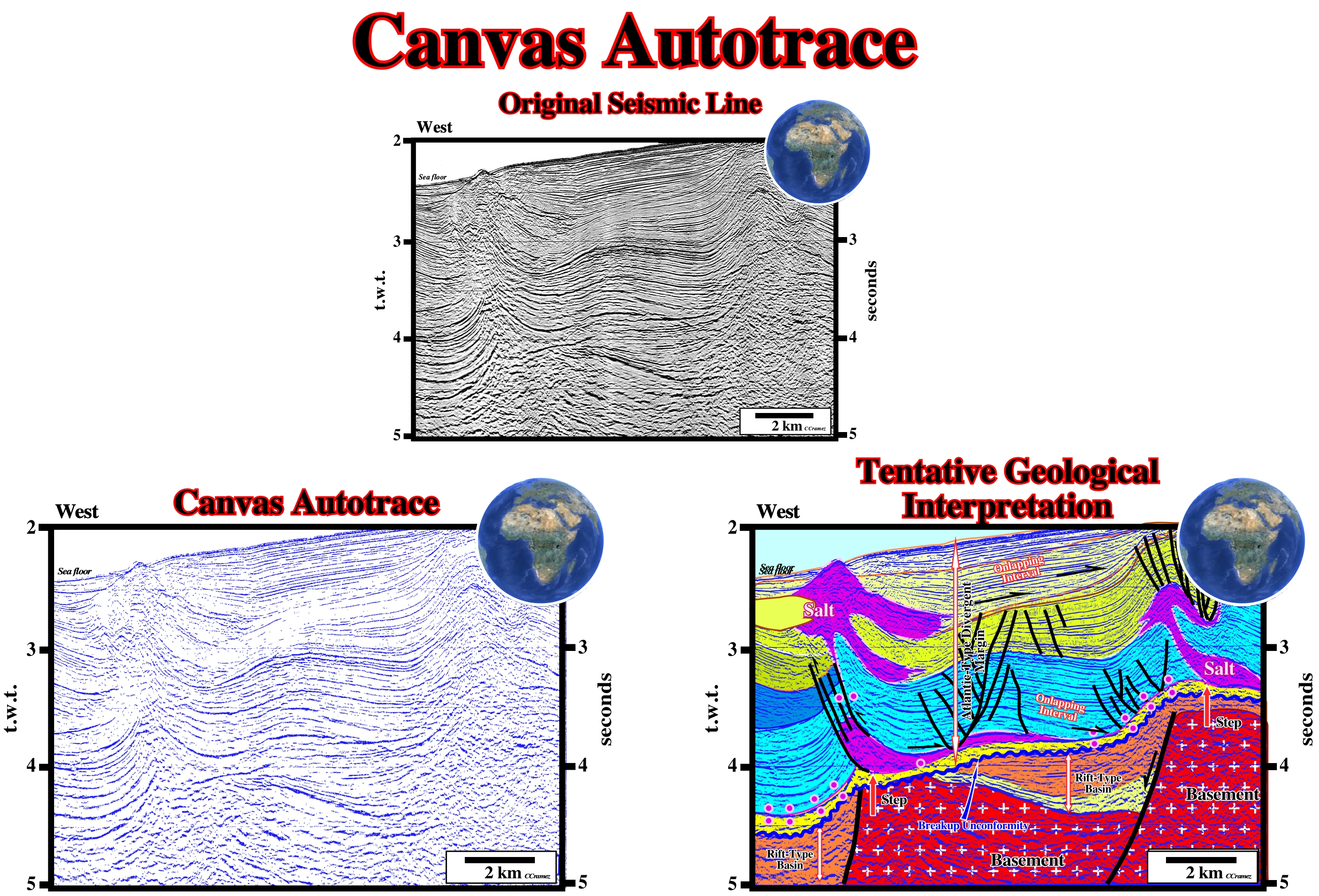
When Canvas performs an autotrace, the original image is not changed. When the tracing is complete, you can move the vector objects away from the image. Canvas autotraces high-resolution images are better than low-resolution images. Autotracing an image with a resolution lower than 300 ppi can produce jagged paths. Canvas traces an image with curves or straight path segments. Autotracing usually produces several paths that follow various sections of the image. After tracing and group the resulting paths mus be edit. Contrariwise to a scan of a seismic line, an Canvas autotrace can not be reprocesses. On this plate, you find the original seismic line (in the top), a classic Canvas autotrace (generally in blue) and a tentative geological interpretation of the autotrace, in which buried salt steps are quite evident, as well as a salt glacier.
Cap Rock
An impervious body of anhydrite and gypsum, with minor calcite and, sometimes, with sulphur, overlying the salt body, or plug. It results, probably, from the accumulation of the less soluble minerals of the salt body during leaching in the course of its ascent. A cap rock effect is a sharp positive anomaly superimposed on a broader negative, indicative of a salt dome. It is, commonly, produced by the dense cap rock of the dome, but very shallow salt is denser than the surrounding sediments, so the cap rock is not essential in producing this effect.
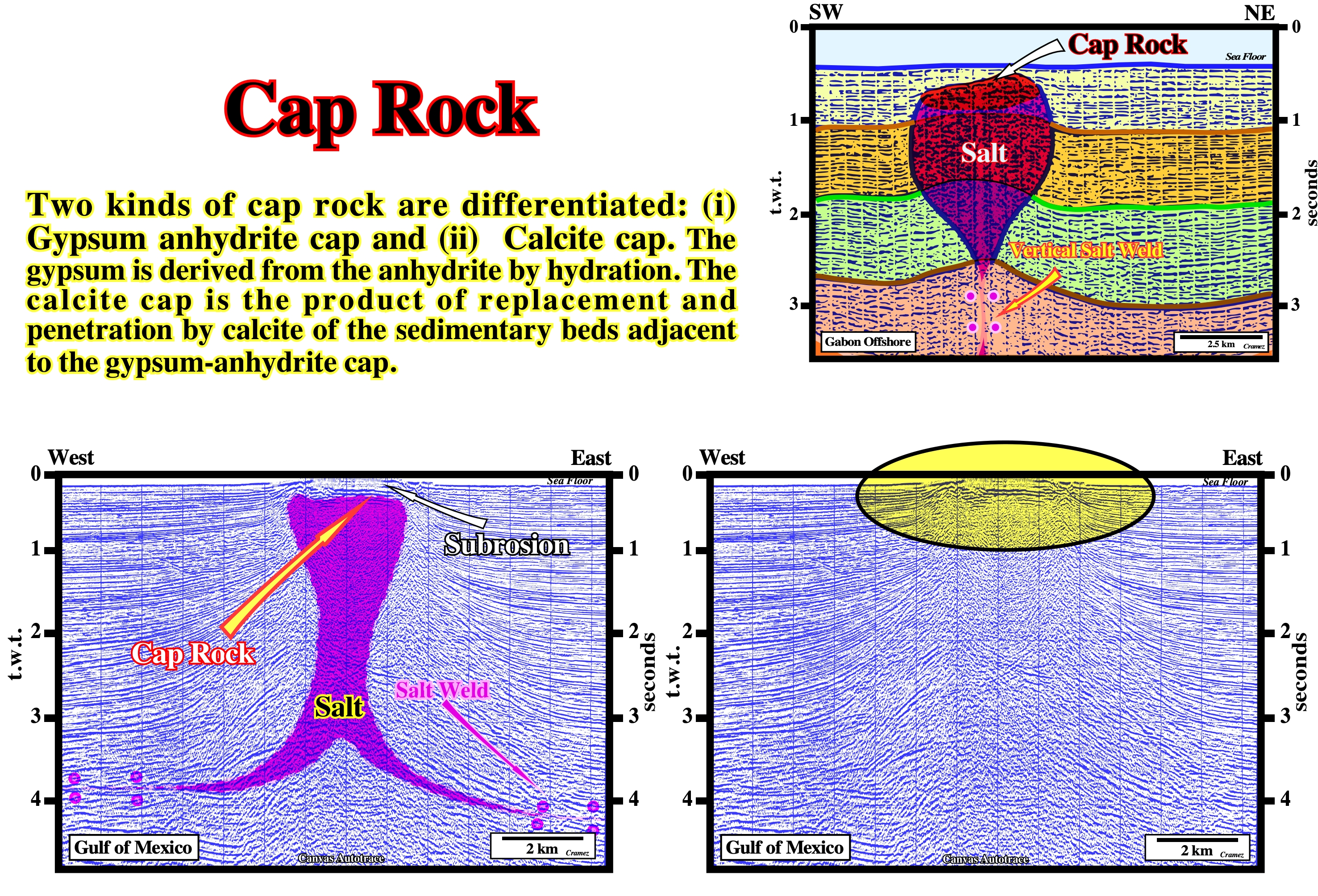
On this tentative geological interpretation of a Canvas autotrace of Gabon offshore seismic line, a cap rock is, easily, recognized, just above of the bulb of a diapiric salt structure, by an anomalous amplitude of the associated seismic marker. Such anomalous amplitude is created by the strong acoustical impedance generated by the impervious bodies of anhydrite and gypsum.
Carboniferous Salt Deposits (Zharkov, M. A., 1984)
Carboniferous salt deposits have been recognized in the following basins: Chu-Sarysu, Mid-Tien Shan, Sverdrup, Williston, Paradox, Eagle, Maritime and Saltville.

The basins with Carboniferous evaporites are: (1) North Siberia ; (2) Pechora-Novaya Zemlya ; (3) Spitsbergen ; (4) Northumberland ;(5) North Ireland ; (6) Central England ; (7) Dobruja ; (8) East European ; (9) East Uralian ; (10) Teniz ; (11) Chu-Sarysu ; (12) Chimkent ; (13) Mid-Tien Shan ; (14) Tyup ; (15) Aksu ; (16) Achkkil ; (17) Lhasa ; (18) Fitzrov ; (19) Radames ; (20) Illizzi ; (21) Ahnet ; (22) Reggane ; (23) Tindouf ; (24) Sverdrup ; (25) Maritime ; (26) Saltville ; (27) Michigan ; (28) Illinois ; (29) South Iowa ; (30) Williston ; (31) East Wyomin ; (32) Eagle ; (33) Paradox ; (34) San Juan ; (35) Orogrande ; (36) Venezuela ; (37) Amazon ;(38) South Peruan.
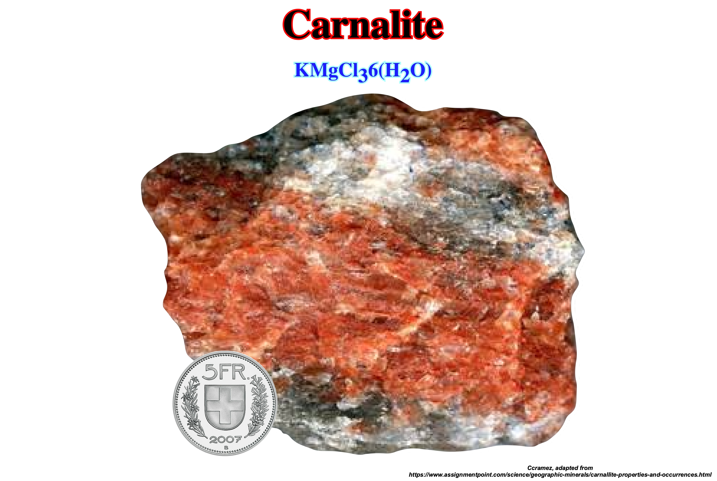
Carnalite
A milk-white to reddish orthorhombic mineral: KMgCl36H2O. It occurs as a residue. It is a raw material of fertilizer manufacture in some European districts.
It is, usually, massive to fibrous with rare pseudohexagonal orthorhombic crystals. The mineral is deliquescent, that is to say, it absorbs moisture from the surrounding air. Th specimens must be stored in an airtight container. Carnallite occurs with a sequence of potassium and magnesium evaporite minerals: sylvite, kainite, picromerite, polyhalite, and kieserite. Carnallite is an uncommon double chloride mineral that only forms under specific environmental conditions in an evaporating sea or sedimentary basin. It is mined for both potassium and magnesium. It occurs in the evaporite deposits of Carlsbad, New Mexico, in Paradox, Williston and Perm geographic basins, Colorado and Utah, Stassfurt, Germany, Russia and Saskatchewan (Canada). These deposits date from the Devonian through the Permian periods. In contrast, both Israel and Jordan produce potash from the Dead Sea using evaporation pans to further concentrate the brine until carnallite precipitates, dredging the carnallite from the pans and processing to remove the magnesium chloride from the potassium chloride (https://www. assignmentpoint.com/science/geographic-minerals/carnallite-properties-and-occurrences.html).
Ca-Smectite (American Geological Institute, 1999)
Group name for 2/1 phyllosilicate clay minerals with layer charge between 0.2 and 0.6 per formula unit. They take polar liquids into the interlayer space causing them to swell in a direction perpendicular to the 001 surface. They have cation exchange capacity (CEC). The total capacity of a soil to hold exchangeable cations of about 110 cmolckg-1 for soil smectites, and variable interlayer spacing.

The smectite minerals are derived from the alteration of volcanic glass and from the weathering of primary silicates. They are the chief constituents of bentonites and fuller's earth (any clay material that has the capability to decolonize oil or other liquids without the use of harsh chemical treatment). They are common in soils, sedimentary rocks, and some mineral deposits.
Cenozoic
The upper erathem of the Phanerozoic Eonothem, in the Standard Global Chronostratigraphic Scale. The Cenozoic is the time during which the Tertiary and Quaternary were formed. The Cenozoic Period extends from 65 Ma to the Present.
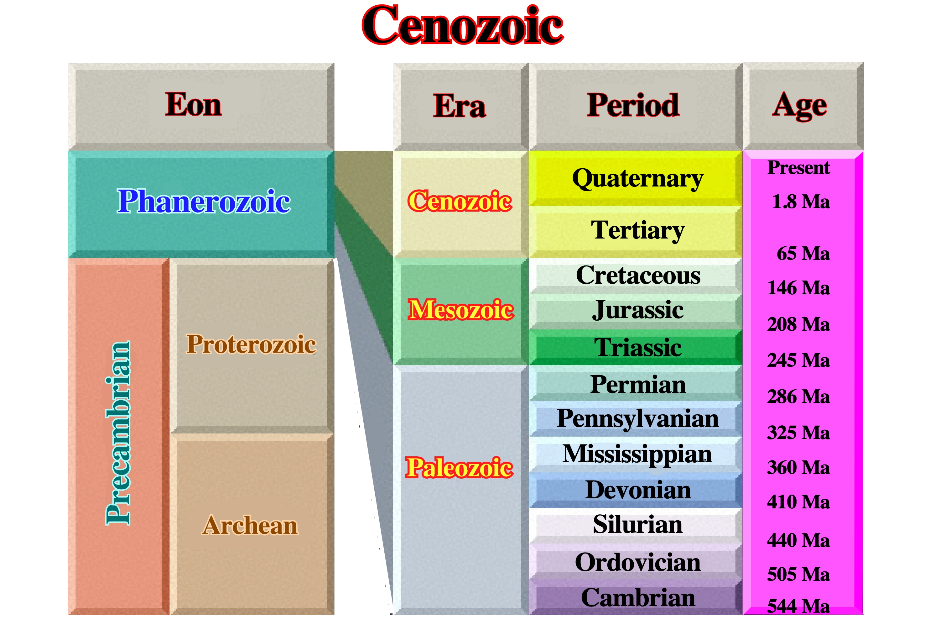
The Cenozoic Era is the most recent of the three major subdivisions of animal history. The other two are the Mesozoic and Paleozoic Eras. The Cenozoic spans only about 65 million years, from the end of the Cretaceous Period and the extinction of non-avian dinosaurs to the Present. The Cenozoic is, sometimes, called the Age of Mammals, because the largest land animals have been mammals during that time. However, this is a misnomer for several reasons. First, the history of mammals began long before the Cenozoic began. Second, the diversity of life during the Cenozoic is far wider than mammals. The Cenozoic could have been called the "Age of Flowering Plants" or the "Age of Insects" or the "Age of Teleost Fish" or the "Age of Birds" just as accurately. The Cenozoic is divided into three periods: Paleogene (±65.5 to ± 23 Ma), Neogene (±23 to ±2.6 Ma) and the Quaternary (±2.6 million Ma). Paleogene and Neogene are, relatively, new terms that now replace the deprecated term, Tertiary. The Paleogene is subdivided into three epochs: Paleocene (±65.5 to ±55.8 Ma), Eocene (±55.8 to ±33.9 Ma), and Oligocene (±33.9 to ±23 Ma). The Neogene is subdivided into two epochs: Miocene (±23 to ±5.3 Ma) and Pliocene (± 5.3 to 2.5 Ma). (https://ucmp.berkeley. edu/cenozoic/cenozoic.php).

In terms of Sequence Stratigraphy, the Cenozoic corresponds, roughly, to the regressive phase of the post Pangea continental encroachment stratigraphic cycle, i.e., the period during which the continents, individualized by the breakup of the Pangea, assembled to create a new supercontinent. Due to the collision between the continents of different lithospheric plates, the volume of the oceanic basins increased, and the absolute (eustatic) sea level falls. The onset of the eustatic sea falling started, immediately, after the Cenomanian-Turonian, around 30 million years before the beginning of the Cenozoic.
Characteristic Wavelength (δc)
Theoretical periodic spacing of the fastest mode of growth of an instability, represented by the principal eigenvalue (the special value of a variable parameter for which the solution of an equation is nontrivial) of growth rate k*m. Amplitude of the displacement at time "t" on the interface is: yi (t) = yi (0) exp (k*m qt), where "yi " is the amplitude of perturbation on layer "i" and "q" is the scaling factor "s-1" (Ramberg, 1981).

Assuming the diapiric structures are connected with the mother salt layer, Goguel (1983) suggested the distance between salt domes is, more or less, constant. In physical terms, it can be said that there is a dominant wavelength (δc) or an observed space of instability. The characteristic wavelength can change if the interface was initially deformed or if the Rayleigh-Taylor instability is influenced by others effects, such as differential loading, regional strain, thermal convection, faulting, etc.
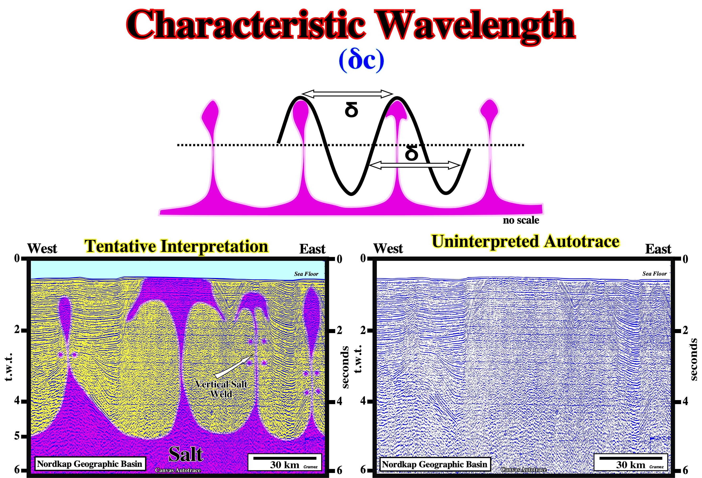
Salt disturbance as waves have a characteristic wavelength, which is expressed in meters. The wavelength is the distance between any two adjacent points which are in phase. Two points in phase are separated by an integer number (0,1,2,3...) of complete wave cycles. They do not have to be peaks or troughs, but they must be separated by complete number of waves. On the field, the rock characteristics change, laterally. The distance between consecutive disturbances (salt domes, for instances) can change significantly. On the preliminary tentative geological interpretation of a Canvas autotraces of a Nordkap geographic basin seismic line, the distance between the salt domes is roughly constant. The proposed interpretation takes into account a salt dome with vertical walls is a physical impossibility. A simple depth conversion of such salt domes, indicates that the bottom of the salt (at the vertical of the salt domes) is much deeper that the bottom of the basin, which is impossible.
Chlorite (American Geological Institute, 1999)
A group of platy, monoclinic, usually greenish minerals with the general formula (R+2R+3)6Al SiO3O10(OH)i8. There are four subgroups of this 2:1 layer clay mineral (the interlayer hydroxyl sheet is to be treated like other interlayer material): (i) Trioctahedral chlorite (the most common chlorites), in which both the octahedral sheet sandwiched between tetrahedral sheets and the interval one are trioctahedral ; (ii) Dioctahedral chlorite with both octahedral sheets dioctahedral (e.g., donbassite) ; (iii) Di / trioctahedral chlorite with the octahedral sheet in the 2:1 layer dioctahedral, but with the hydroxyl sheet trioctahedral (e.g., cookeite or sudoite) and (iv) Tri / dioctahedral with the 2:1 layer trioctahedral, but with the hydroxyl sheet dioctahedral (no examples of this mineral have yet been found).
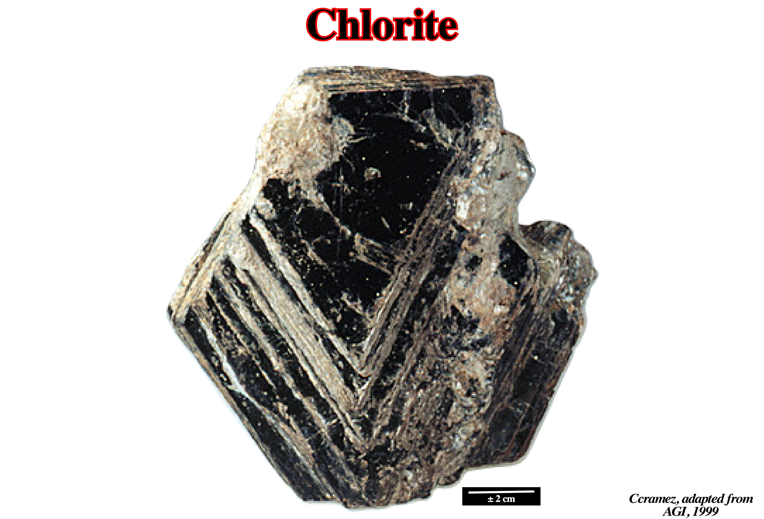
The most common chlorites, trioctahedral ones, are named according to the dominant cation/ Fe-rich is chamosite, Mg-rich is clinochlore, N-rich is nimite (acronym for the National Institute of Metallurgy of South Africa), and Mn-rich is pennantite. Chlorite minerals most, often, form in rock environments where minerals are altered by heat, pressure, and chemical activity. They form at temperature less than a few hundred degrees, within a few miles of Earth's surface. Chlorite minerals form, often, in clay-rich sedimentary rocks buried in deep sedimentary basins or subjected to regional metamorphism at a convergent plate boundary. Chlorite is, usually, associated with biotite, muscovite, garnet, staurolite, andalusite or cordierite. Metamorphic rocks rich in chlorite might include phyllite and chlorite schist. Another environment of chlorite mineral formation is in oceanic crust descending into subduction zones, where amphiboles, pyroxenes and micas are altered into chlorite. Chlorite minerals form, also, during the hydrothermal, metasomatic, or contact metamorphism. These chlorite minerals are found, often, in fractures, solution cavities or tin vesicles of igneous rocks. (https://geology.com/minerals/chlorite.shtml).
Chloritisation
The replacement by conversion into or introduction of chlorite (group of platy, monoclinic, usually, greenish minerals with the general formula: (R+2R+3)6AlSi3O10(OH)8).

Presence of pennine minerals as result of serve chloritization in basaltic andesite. Chloritization is the alteration of pyroxene or amphibole minerals into the chlorite group minerals. Chloritization is a common process in metamorphic transitions to the greenschist facies, and amphibolite facies retrograde metamorphism (https://en.wikipedia.org/wiki/Mineral_alteration#Chloritization).
Clinopyroxene (American Geological Institute, 1999)
A group name for pyroxenes crystallizing in the monoclinic system containing, sometimes, considerable calcium, with or without aluminum, and alkalies.

Any monoclinic mineral of pyroxene group, such as diopside, hedenbergite, clinoenstatite, acmite, pigeonite, spodumene, jadeite and omphacite belongs to the clinopyroxene group.
Coastal Depositional Break
See Depositional Coastal Break
Depositional coastal break (DCB) is more correct than the disused coastal depositional break. The depositional coastal break is, more or less, the shoreline. This is particularly true on the seismic lines, since the seismic resolution is around 30/40 m. As illustrated above, depositional coastal breaks are, easily, recognized in the transgressive interval of a sequence-cycle. On the proposed tentative geological interpretation of a Canvas autotrace of a Kalimantan offshore (Indonesia) seismic line, a relative sea level rise in acceleration (increasingly important marine ingressions) initiates the deposition of an highstand systems tracts group (HSTG), above a lowstand systems tracts group (LSTG). The HDTG is formed by the transgressive interval (TI) and highstand prograding wedge (WPW). The LSTG is formed by the submarine basin floor fans (SBFF), submarine slope fans (SSF) and by the lowstand prograding wedge (LPW). However, just the lowstand prograding wedge (LPW) is visible on this detail of the seismic line. The rise of the relative sea level (local and referenced to any fixed point of the Earth's surface, which can be the seafloor or the top of the continental crust) induces a continentward displacement of the depositional coastal break creating a shelf (continental platform). As a rise of relative sea level is not in continuity, geoscientists speak of single marine ingression and composite marine ingression. A single marine ingression is just an increment (step) of a composite marine ingression. Each single marine ingression (first eustatic paracycle), is followed by a stability period of the relative sea level, during which the shoreline moves seaward, as the sediments prograde towards the continental edge. However, the shoreline does not reach the position it had before (retrogradation). It is during the stability period of the relative sea level that the 1st sequence-paracycle is deposited. Thus, as depicted on the above tentative interpretation after the deposition of the 1st sequence-paracycle, the 2nd rise of the relative sea level (2nd single marine ingression or 2nd eustatic paracycle) is more important than the first one. As the relative sea level continues to rise in acceleration, again, the shoreline is shifted landward increasing the extension of the shelf and the water-depth. A new period of relative sea-level stability allows, again, the seaward displacement of the shoreline and the deposition of progradational sediments (2nd sequence-paracycle), but the shoreline does not reaches the position it had at the end of the preceding sequence-paracycle. This mechanism (relative sea level rise - stability of the relative sea level - relative sea level rise, etc., etc,) continues until the first rise, in deceleration, of the relative sea level (smaller than the previous one) initiates the deposit of the highstand prograding wedge (LPW). Globally, these geological events develop a retrogradation as illustrated on the tentative geological interpretation. What certain geoscientists, incorrectly, call transgression (continentward displacement of the shoreline and associated coastal deposits), is nothing more than a succession of increasingly important marine ingressions and increasingly smaller sedimentary regressions. It is this set of marine ingressions and sedimentary regressions, which globally develop a retrogradational geometry, that Cesare Emiliani (1992) called "Transgressions" (not transgression).
Collision Zone
Synonym of salt suture, in salt tectonics.
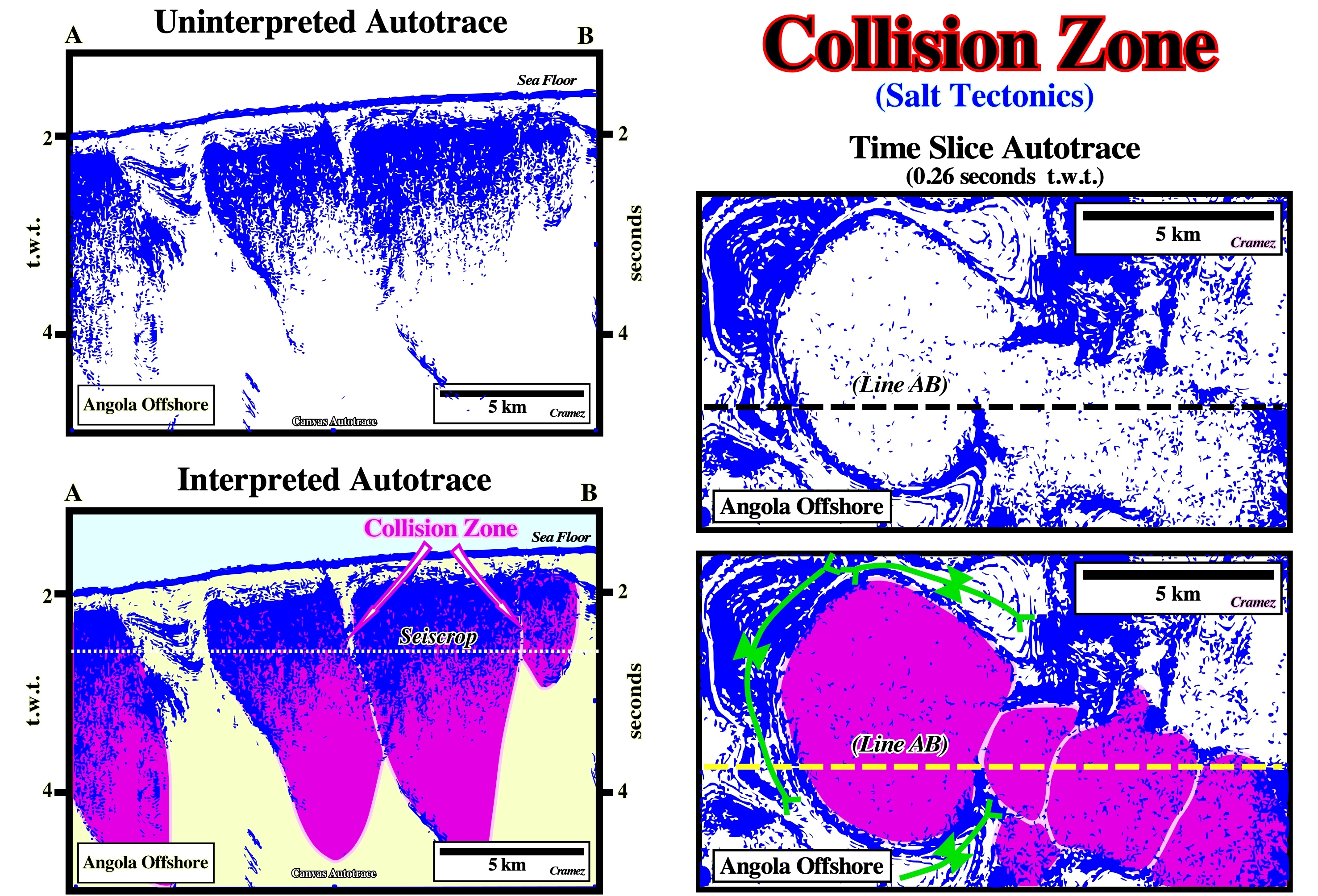
As illustrated on the Canvas autotrace of an Angola offshore seismic line, a collision zone or salt suture is a junction between salt structures that have coalesced, laterally, to form a salt canopy. Incomplete collisions have lensoid synforms of the overburden along them. Complete collisions have folds in the overburden above them: either the suture is below a subsided cuspated synform or it is the junction of a pair of appressed, raised salt antiforms. Several salt sutures are evident on the 0.26 seconds time slice autotrace illustrated on this figure.
Compensatory Subsidence
Local subsidence induced by salt flowage or salt withdrawal. Compensatory subsidence is, mainly, associated with halokinesis and salt tectonics, as well as, with shalokinesis. Flowage of a salt layer induces a local increasing of the available space for sediments (accommodation) independently of eustasy and tectonic subsidence.
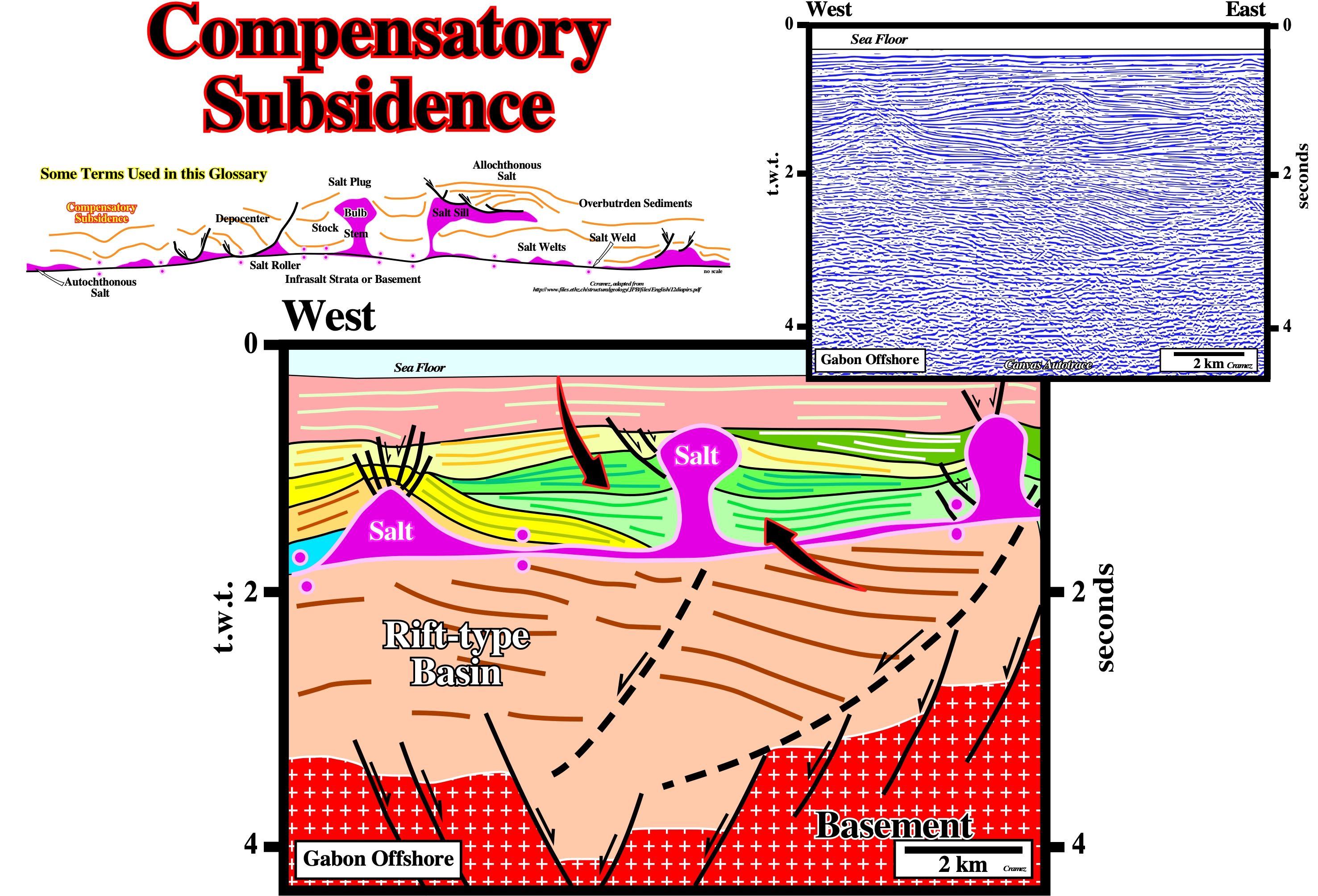
On this tentative interpretation of a Canvas autotrace of Gabon offshore seismic line, the basement (granite-gneiss + Paleozoic sediments) is overlain by rift-type basin sediments, which are overlain by a divergent margin sediments. The limit between the sediments of the rift-type basin and those deposited in the divergent margin, i.e., the breakup unconformity (BUU), is not to evident (probably the thickness of the infrasalt margin sediments is under seismic resolution). Apparently, the breakup unconformity seems to be at the bottom of the evaporitic layer (purple). As the bottom of the salt layer is roughly subhorizontal, a tectonic subsidence cannot be invoked to explain the thickness variations of the overburden. A compensatory subsidence, created by salt flowage, is the hypothesis less falsifiable, so the more likely.
Compressional Structure
A strain induced by a compressional tectonic regime and characterized by a sedimentary shortening (folding or reverse faulting).
The compressional structures (folds and thrusts), recognized on the central part of this tentative geological interpretation, are the consequence of a local compressional tectonic regime created as a counterpart of the up-dip extensional tectonic regime responsible for the lengthening of the sediments recognized on the left part of the line. A compressional regime (σ1 horizontal) induces a shortening, while an extensional regime (σ1vertical) induces a lengthening. The term compressional does not means that σt (tectonic stress) is positive, as considered, often.
Compressional Tectonic Regime
Tectonic regime characterized by an horizontal oblong effective stresses ellipsoid with σ1 horizontal. As illustrated below, two major compressional tectonic regimes (σt >0 ) can be individualized.
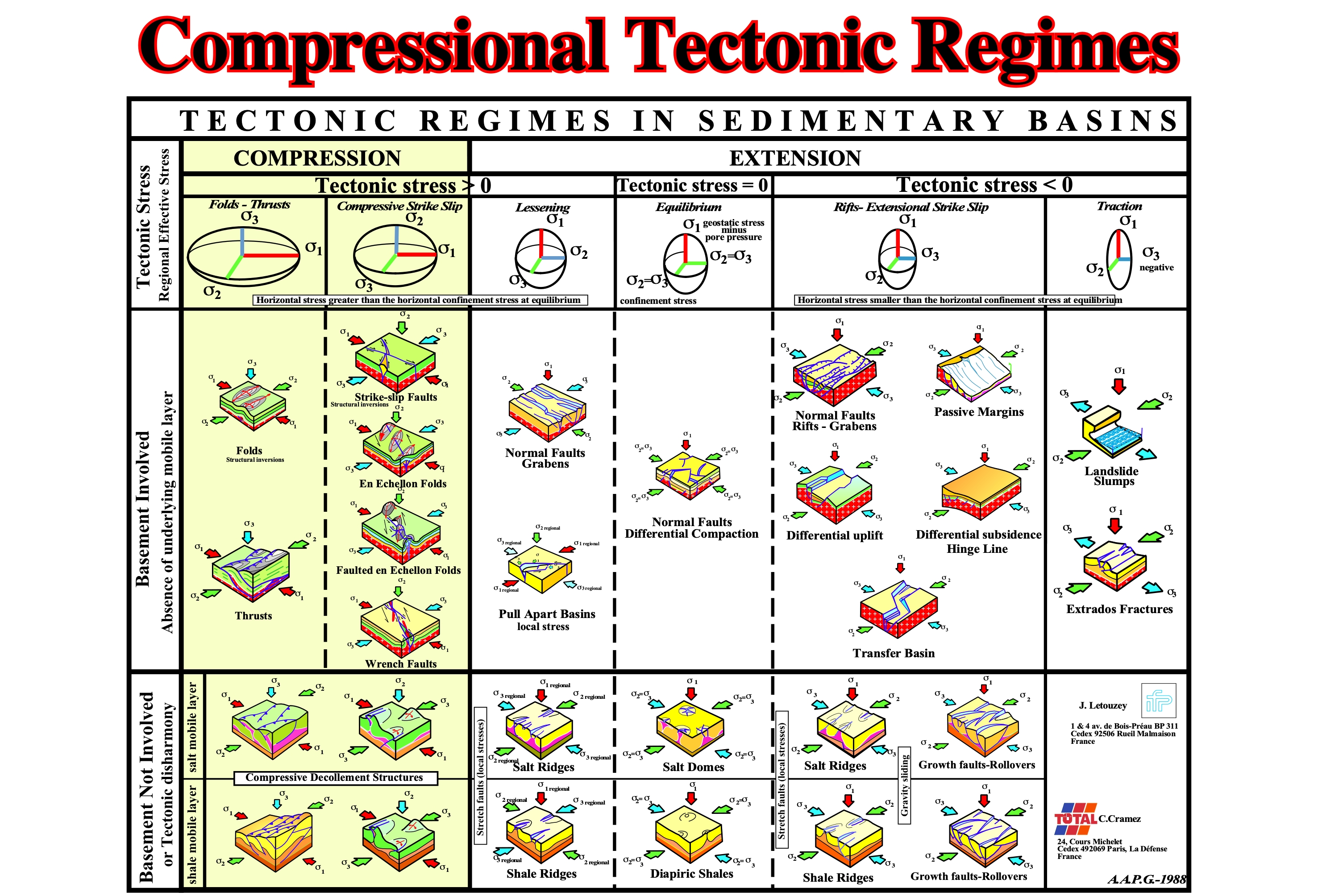
When the tectonic stress is positive (σt > 0) and the maximum effective stress (σ1) vertical, the sediments are shortened or compressed. However, they can be shortened in two different ways: (i) cylindrical-folds and thrust-faults, when the minimum effective stress (σ3) is vertical and (ii) conical-folds and associated strike-slip faults, as well as wrench faults. The stress ellipsoids in compression and in extension are quite different. A positive tectonic stress (σt > 0) occurs in compression as well as in extension.
Confining Pressure (American Geological Institute, 1999)
All equal, all-sided pressure around a specific volume of material, e.g., geostatic pressure or hydrostatic pressure. See also lateral confining pressure.
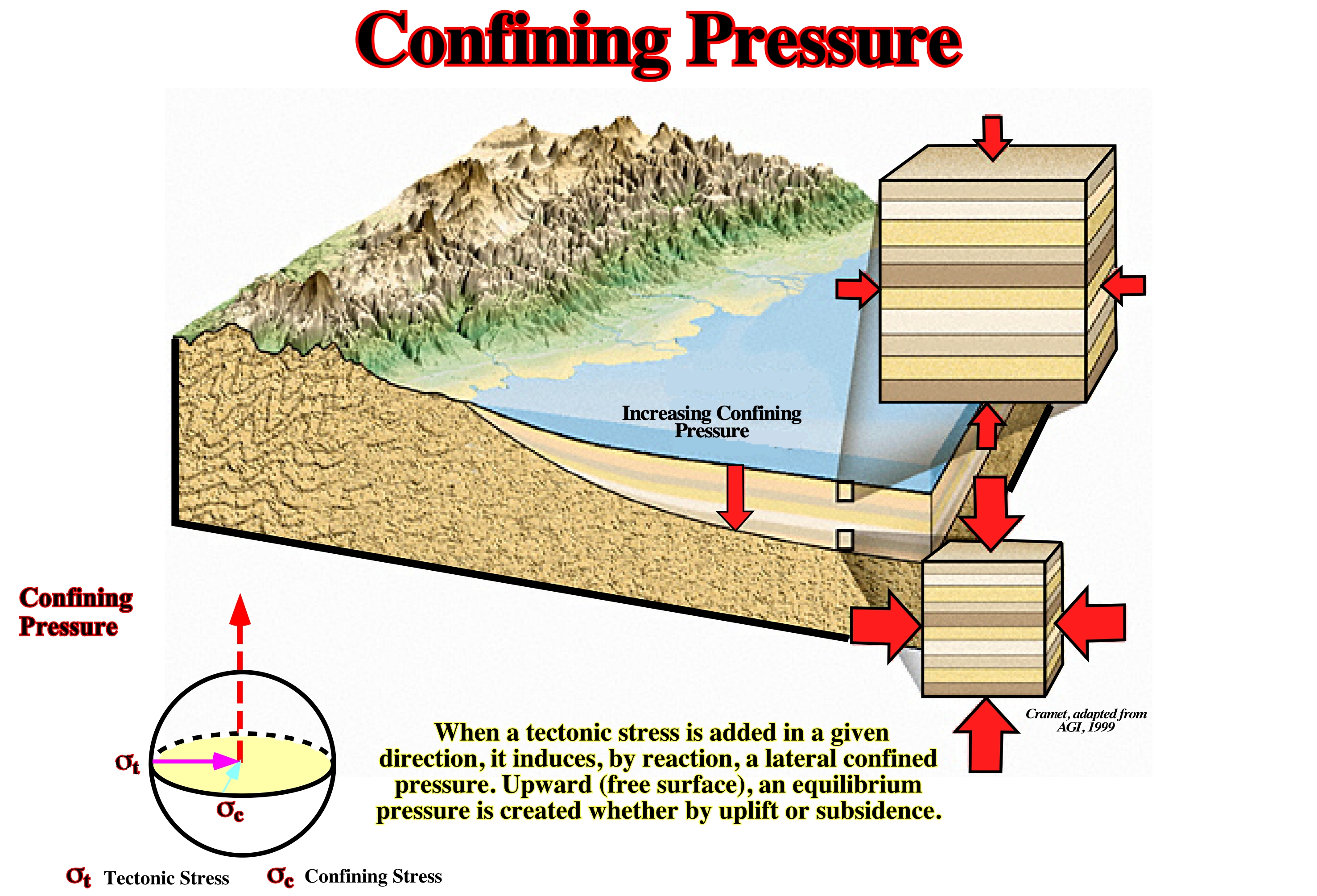
Confining pressure (total weight of the interstitial pore water and rock above a specified depth) increases with depth. The geostatic pressure (lithospheric pressure) ellipsoid, in depth, has a tendency to become uniaxial, i.e., as an hydrostatic pressure or pore pressure ( pressure that is exerted by a fluid at equilibrium at a given point within the fluid, due to the force of gravity).
Conical-Folds
A fold model that can be described, geometrically, by the rotation of a line about one of its ends, which is fixed. In a stereographic projection, contrariwise to cylindrical-folds, in which the dip of the flanks lie on meridians, in conical-folds, the dip of the flanks lie in a parallel. Conical-folds are associated with strike-slip movements of the basement and strike oblique to the maximum effective stress (σ1).
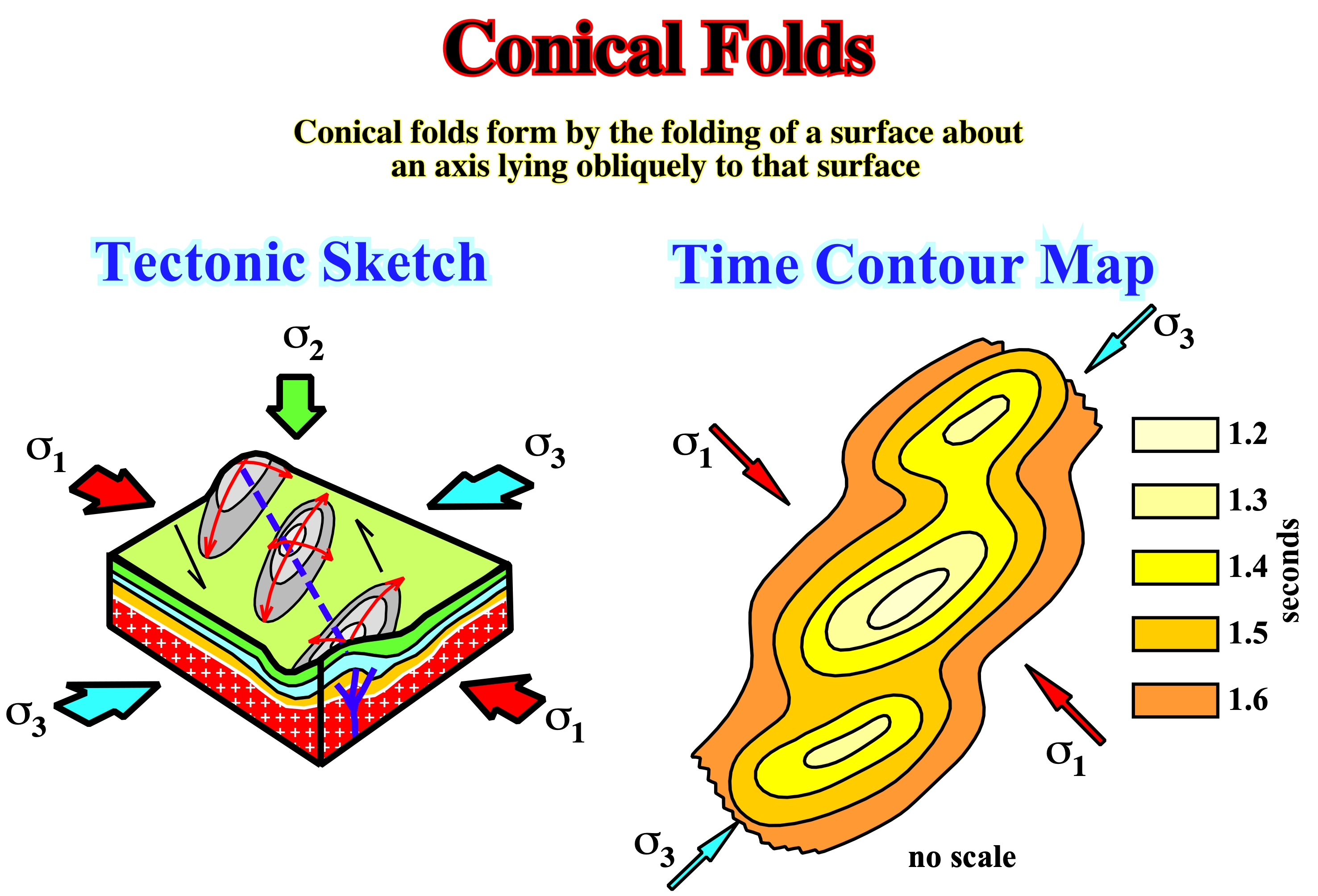
Depending on the amplitude of the strike-slip movement of the basement, the shortening of the sedimentary cover is quite different. When the displacement is, relatively, small (less than 5 km), the cover is shortening by en-echelon folds. When the displacement is higher than 5 km, let's say 10 km, folding is insufficient to short the sediments, therefore en-echelon folds are faulted by reverse-faults. These faults are the surface evidence of a deep strike-slip faulted zone. When the lateral displacement is important (25 km or more), a wrench fault zone is formed, in surface, with more or less discontinuous outcrops of the basement.
Constrained Growth (Salt)
A diapiric growth vertically or laterally restricted by the strength of the diapir's overburden. An example is a forceful intrusion at moderate depths, characteristic of active piercement. In contrast, unconstrained growth includes overturns of Raleigh-Taylor instability, passive piercement, shallow injection of salt sheets into weak sediments, very shallow vertical intrusion by active piercement, extrusive protuberance of diapir, and glacial flow.
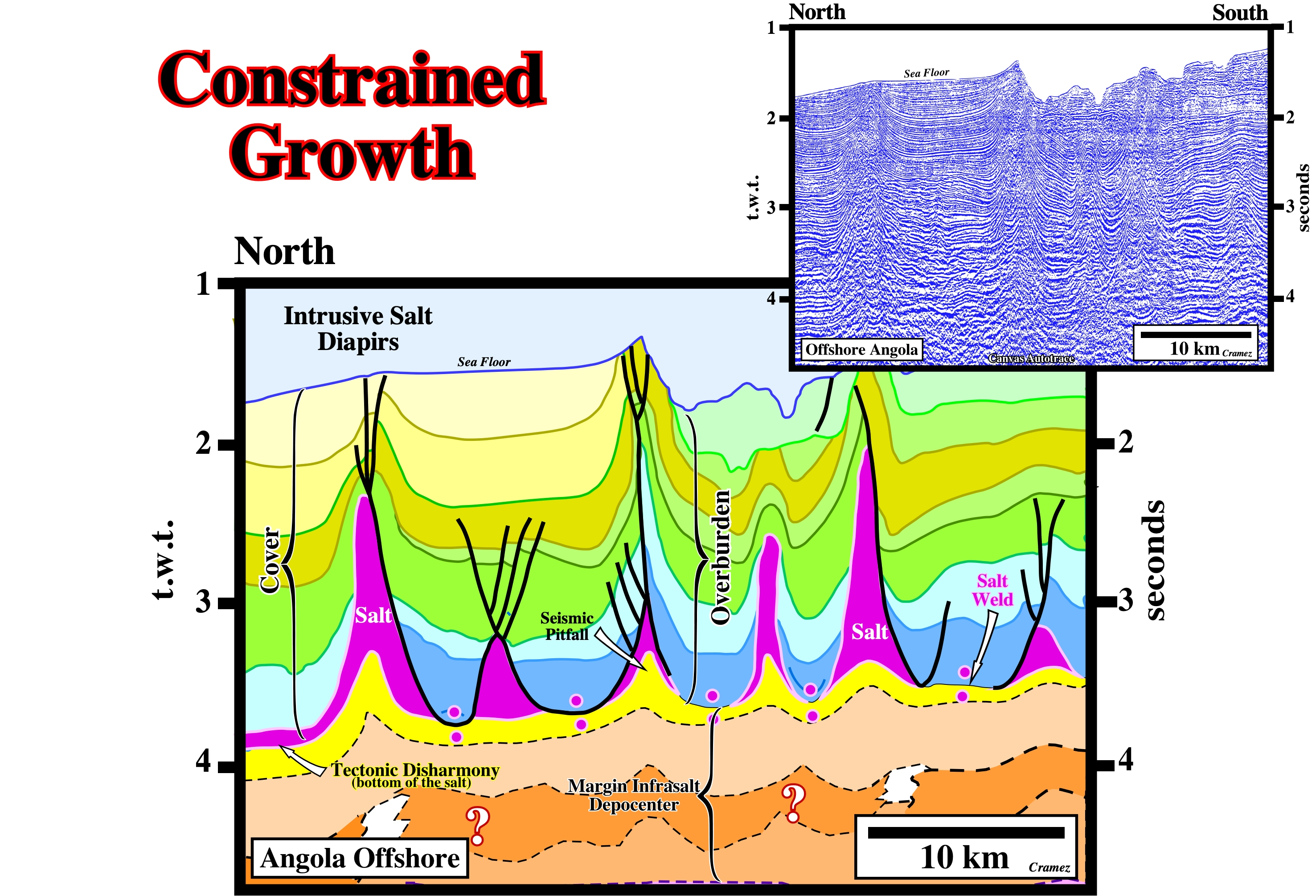
Salt domes can be intrusive and extrusive. Intrusive salt domes, as illustrated on this geological tentative of a Canvas autotrace of an Angola offshore seismic line, never outcrop. They do not reach the surface and they develop under a constrained or forced growth. Extrusive salt domes can reach the surface. They induce an apparent diapirism as sedimentation progresses. On this tentative interpretation, the tectonic disharmony between the infrasalt strata and the cover (salt + overburden), strongly, suggests halokinesis is dominant. Some diapirs seem to be, slightly, squeezed. The characteristic wavelength of the salt structures (the distance between the salt structures) is, more or less, constant. The undulations of the infrasalt sediments have no geological meaning. They correspond, mainly, to seismic pitfalls induced by lateral thickness variations of the salt layer.
Continent
A Earth's major land mass, including both dry land and continental shelves.
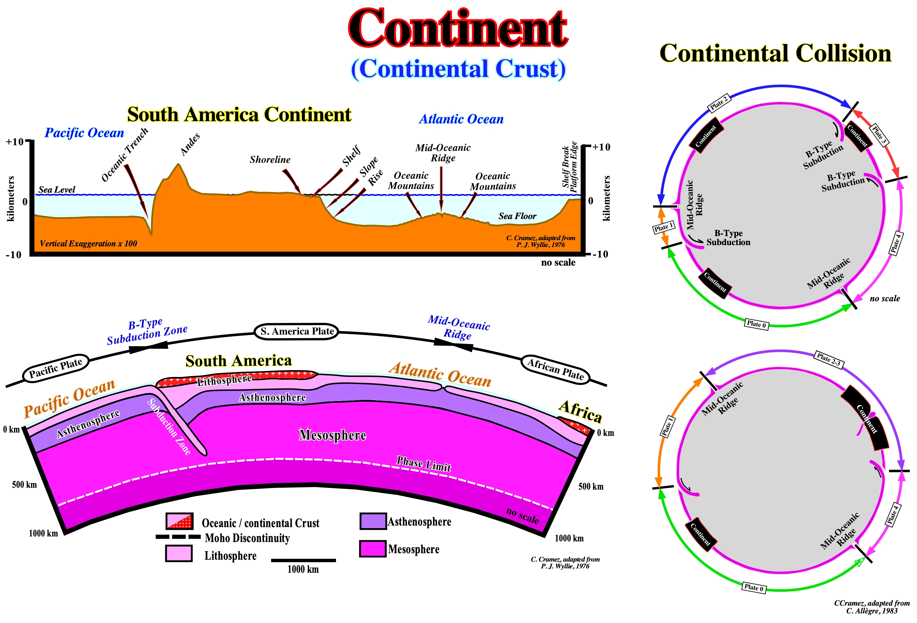
The most likely geological interpretation of the morphological profile illustrated above, between the eastern part of the Pacific Ocean and the western Africa continent, is to assume a B-type subduction zone and a mid-oceanic ridge. The subduction zone is emphasized by the oceanic trench, between the Pacific Ocean and the South America continent. The mid-oceanic ridge, in the middle of the South Atlantic Ocean, separates the separates the South America and Africa lithospheric plates. The South America and Africa continents are just portions of continental crust floating, respectively, on the South America and African lithospheric plates. These continents, as all others, are convoyed by the movement of the lithospheric plates as assumed in Plate Tectonics Paradigm, which can be summarized as follows: (i) The outer and rigid layer of the Earth, i.e., the lithosphere is a mosaic of tectonic plates which move relative to each other, with speeds of the order of a few centimeters per year (speed nail growth in humans) ; (ii) The lithospheric plates arise at the level of the mid-oceanic ridges and they float on a warm plastic layer of the mantle called the asthenosphere ; (iii) The plates move apart without deforming ; (iv) The movement of the lithospheric plates is, directly, linked to oceanic expansion ("sea floor spreading") ; (v) The hot and molten material of the asthenosphere rises through the lithosphere to the summit of the oceanic mountains (ridges) where, cooling, forms the oceanic crust ; (vi) The new oceanic crust is, continuously, moving away from the axis of the mid-oceanic ridges ; (vii) The oceanic crust approaching the continents, part the lithospheric plates are destroyed, at the level of the oceanic trenches, along B-type subduction zones , by sinking into the mantle (in this process, only the oceanic parts of the plates are submerged) ; (viii) The continents are, generally, considered as passive objects conveyed by oceanic expansion, however, they do not remain, completely, immune to the mechanisms of plate tectonics ; (ix) The continents or blocks of the continental crust can collide creating large continents ; (x) The limits of the lithospheric plates are mid-oceanic ridges, subduction zones and transforming faults ; (xi) The limits of the lithospheric plates, in general, do not coincide with the Ocean - Continent Boundary (COB) ; (xii) The internal energy of the globe dissipates at the borders of the plates, mechanically (earthquakes, mountain formation, etc.) or thermally (plutons, volcanoes, etc.) ; (xiii) The relative movements of the plates are governed by the mathematical laws of kinematics on a sphere (the relative movement of two rigid spherical caps is, completely, described if one knows the pole of rotation, said Eulerian pole, and the angular speed).
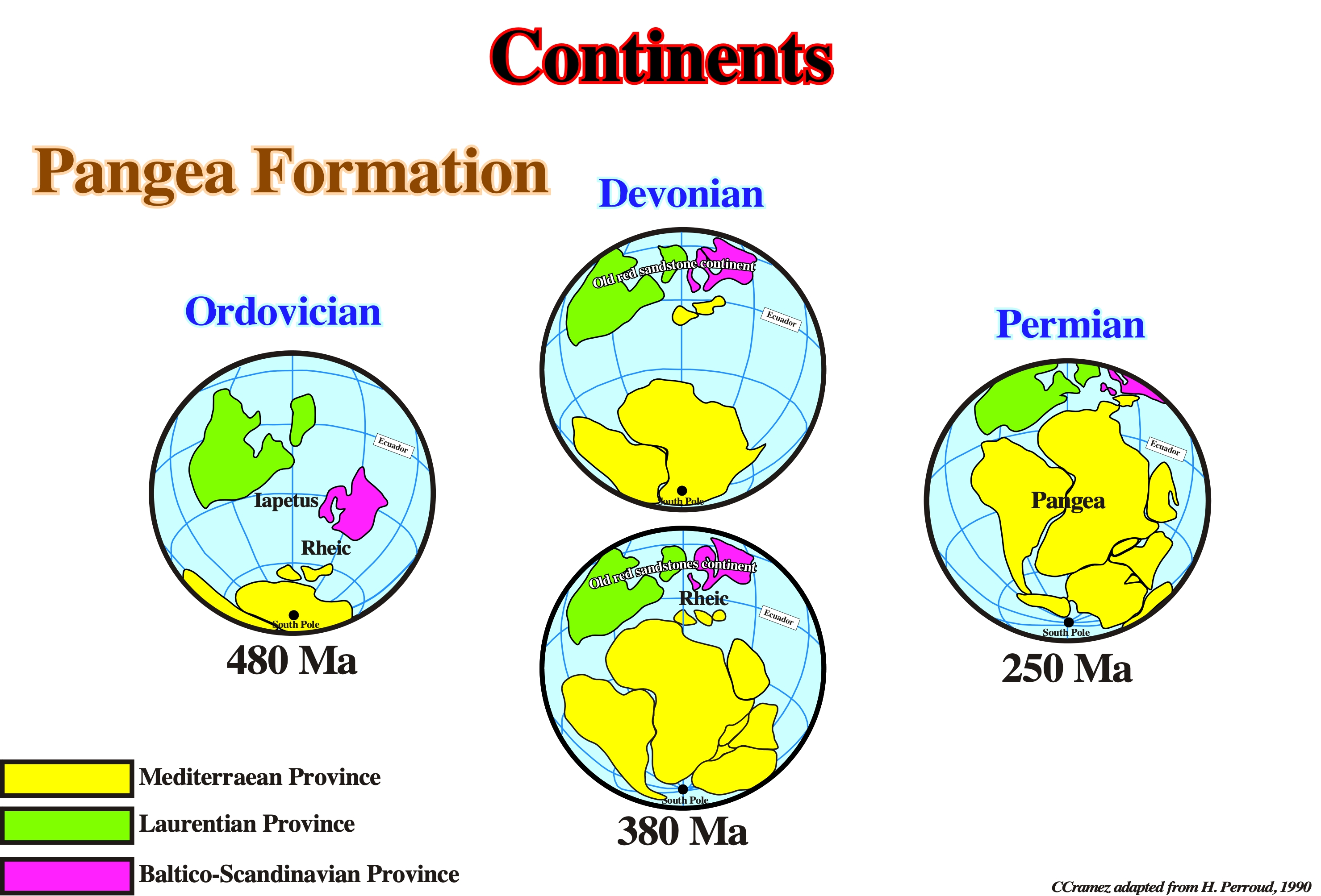
During the Middle and Upper Paleozoic, the positions and shapes of the continents changed quite a lot. This sketch illustrates the progressive gathering of the Paleozoic continents to create the Pangea Supercontinent, at the Permian - Triassic time. Note the closure of the Iapetus and Rheic oceans and the formation of the Old Red sandstone continent, during the aggregation of the Paleozoic continents to form the supercontinent Pangea.
Continental Lithospheric Plate
When the crust of a lithospheric plate is, mainly, composed by sialic rocks, i.e., by rocks rich in silica and alumina.

The lithosphere is composed by (i) the upper mantle and (ii) the crust. When the crust is oceanic, as in the sinking plate in this example, geologists call it a lithospheric oceanic plate. When the crust is composed by sialic rocks, the lithospheric plate is called continental.
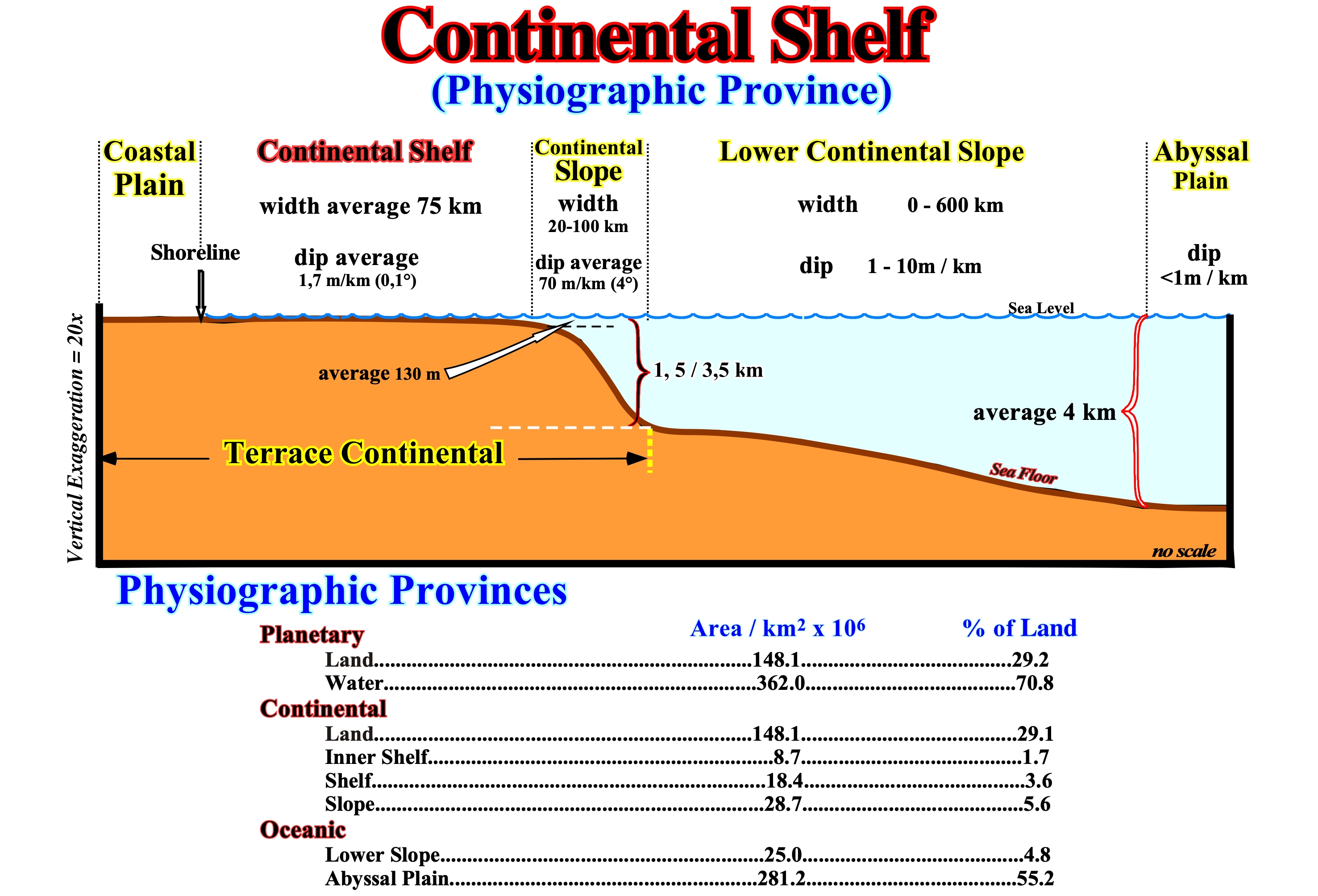
Continental Shelf
The main physiographic provinces are: (i) Coastal Plain ; (ii) Continental Shelf (platform) ; (iii) Continental Slope ; (iv) Lower Continental Slope and (v) Abyssal Plain. The coastal plain, continental shelf and continental slope form the Continental Terrace. Many geoscientists speak just of continental terrace, lower continental slope and abyssal plain. Depending on the position of the sea level and therefore of the shoreline, which separates the offshore from the onshore, the continental shelf may not exist, which is very important, especially, in sequential stratigraphy. When the geological conditions are highstand, i.e., when the sea level is higher than the basin edge, the basin has a shelf. This is what occurs in a sequence-cycle during the transgressive interval (TI) and during the 1st phase of development highstand prograding wedge (HPW), which are subgroups of the highstand systems tracts group). In fact, at the beginning of deposition of the highstand prograding wedge (HPW) of a sequence-cycle, the shoreline is very far upstream of the continental edge: the basin has a shelf. However, as the relative sea level (combined action of the tectonics and absolute or eustatic sea level, which is supposed to be the global and referenced to Earth's center), i.e., due to a marine ingression, the shoreline approaches, progressively, the continental edge reducing the extent of the shelf. Since the shoreline coincides with the shelf break (continental edge), the basin no longer has a shelf. If the relative sea level falls further, a limit develops (unconformity). The geological conditions become truly lowstand with the sea level lower than the basin edge (last continental edge of the preceding sequence-cycle, i.e., before the significant relative sea level fall responsible from the unconformity which emphasizes the in geological conditions change). As illustrated in this sketch, the different physiographic provinces are limited by slope breaks of the depositional surface: (i) The alluvial plain (not shown in this scheme) is limited downstream by the slope break of the bayline, which separates fluvial deposits (upstream) from fluvial/coastal deposits (influenced by relative changes in sea level) ; (ii) The coastal plain is limited between the bayline and the depositional coastal break (roughly the shoreline) ; (iii) The continental shelf, limited between the depositional coastal break and the continental break, has an average width of 75 km, an average slope of 0.1° (± 1.7 m/km) and an average water-depth of 130 meters ; (iv) Upper continental slope, limited between continental edge break and lower continental slope break, has a width ranging from 20 to 100 km and an average slope of 4° (± 70 m/km) ; (v) Lower continental slope, limited between the lower continental slope break and the abyssal plain break, has a width ranging from a few meters to more than 600 km and an average slope between 1 and 10 m/km and (vi) The abyssal plain, limited upstream by the abyssal plain break, generally, has a water-depth of more than 4,000 meters and a slope of less than 1m/km.
Continental Slope
In highstand geological conditions, the continental slope is part of the continental margin between the shelf break and the slope-abyssal plain break. In lowstand geological conditions, the continental slope is part of the continental margin between the shoreline (here the continental edge) and the slope-abyssal plain break.
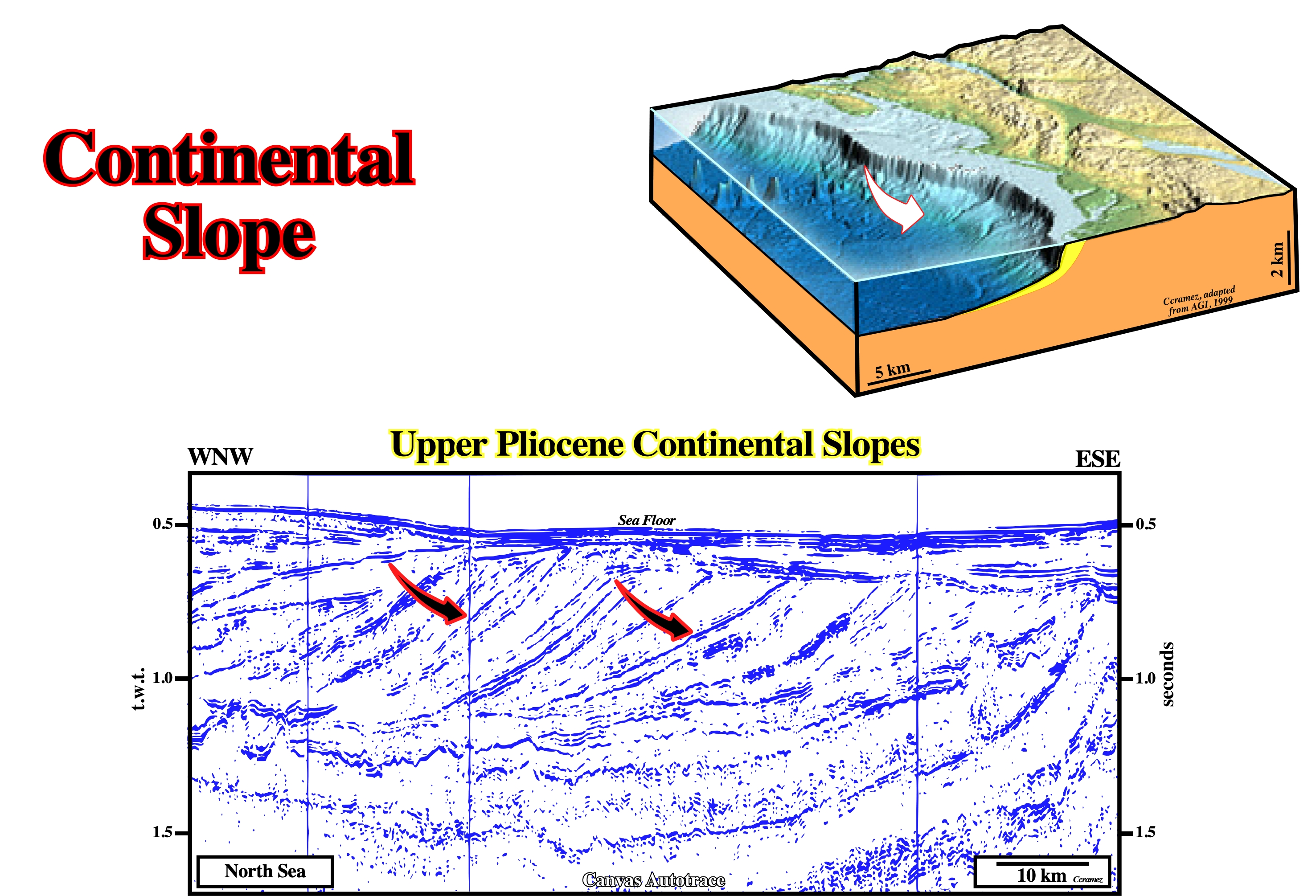
A longitudinal profile of a continental margin shows several breaks. From the continent to deep water, four majors breaks can be recognized: (i) Bayline , (ii) Depositional coastal break, (iii) Shelf break and (iv) Continental slope-abyssal plain break. On seismic lines, to recognize the continental slope, if we do not have a complete profile, we need the geological setting and the horizontal and vertical scales (Geology is scale dependent, see below).
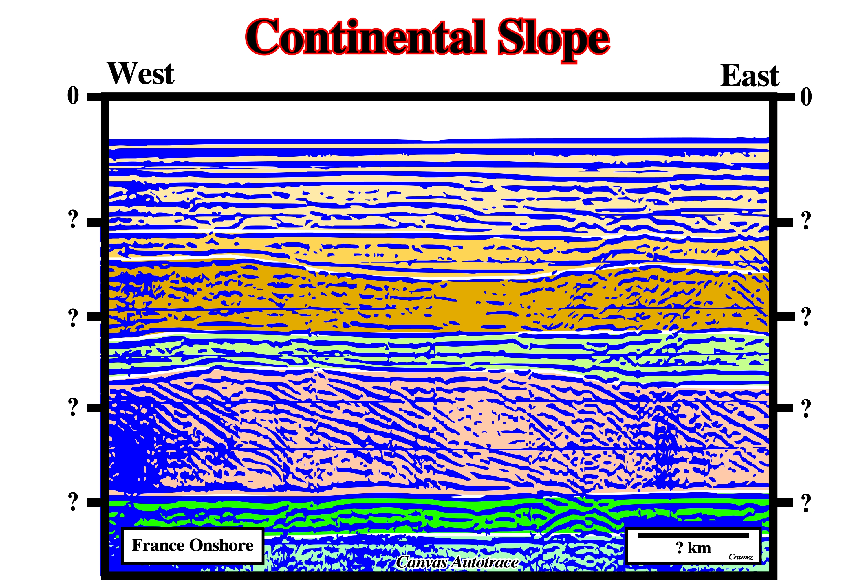
On this line, in which the horizontal and vertical scales were omitted, geoscientists are enable to interpreted the slope recognized on the lower part of the profile. Is it the slope of the bayline break, a delta slope associated with the depositional coastal break or a continental slope associated with the shelf break? For those that often forget that a geological interpretation is scale dependent, the data illustrated above come from a georadar profile. The horizontal scale is metric (50 meters), while the vertical scale is in nanoseconds. The depth thickness of the progradational interval, is around 10-15 meters (groups of inclined layers, which are known as cross-strata.)
Coulomb Coefficient (μ)
Failure during frictional plastic deformation follows the Mohr-Coulomb fracture criterion: τ = τ0 + σn tanφ =τ0 + σnμ, where τ is the shear strength, τ0 is the cohesive shear strength, σn is the normal stress, φ is the angle of internal friction or slope of Mohr envelop, and μ is the Coulomb coefficient.
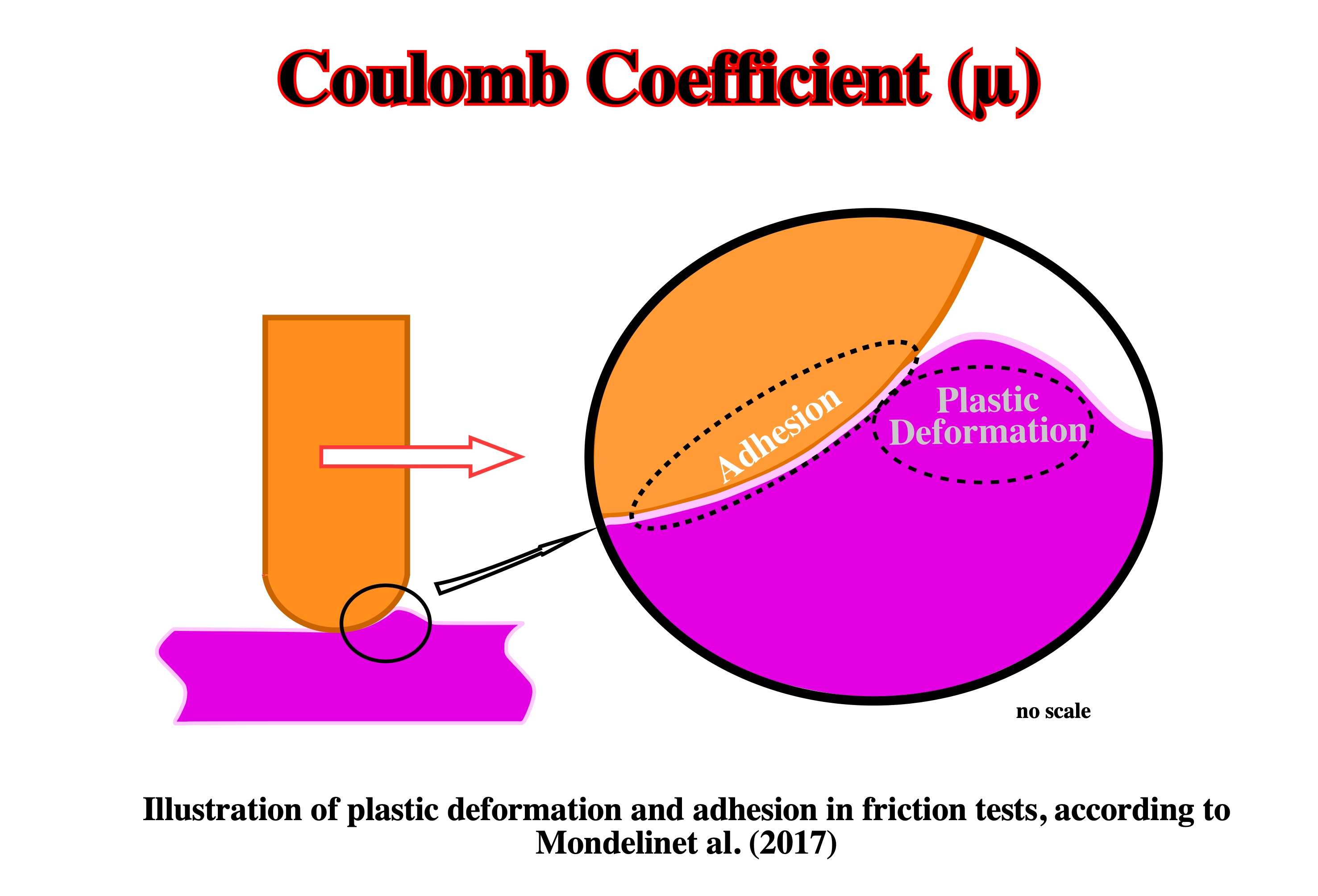
Coulomb's law in mechanics expresses in a very simplified form the intensity of the friction forces exerted between two solids. Depending on whether these solids slide or not against each other, we speak of sliding (dynamic friction) or adhesion (static friction). In both cases, the interactions between these solids include: (i) a normal component σn, which presses them one against the other and (ii) a tangential component τ, which opposes or tends to oppose the slip. As long as the tangential component τ does not reach a certain limit τ0 , the sliding does not occur. We are in adherence situation, However, solids can, eventually, roll, like a bicycle wheel without sliding on the ground. When the limit is reached, slippage occurs. Coulomb's law, which only predicts the intensity from which the slip occurs, determines this limit force τ0 : τ0= μ × σn, where μ is the coefficient of adhesion or coefficient of static friction (sometimes noted μ0 (mu zero), which the value of which depends above all on the two materials present and on the state of their surfaces.
Counter-Regional System
When a growth-fault system, induced by salt evacuation, looks landward (landward vergence). During a progradational loading, allochthonous salt can evacuated in different ways and create two quite different end-members. One with growth faults looking seaward, known, in Gulf of Mexico, as roho systems and another, with growth faults looking landward, known as counter-regional systems.
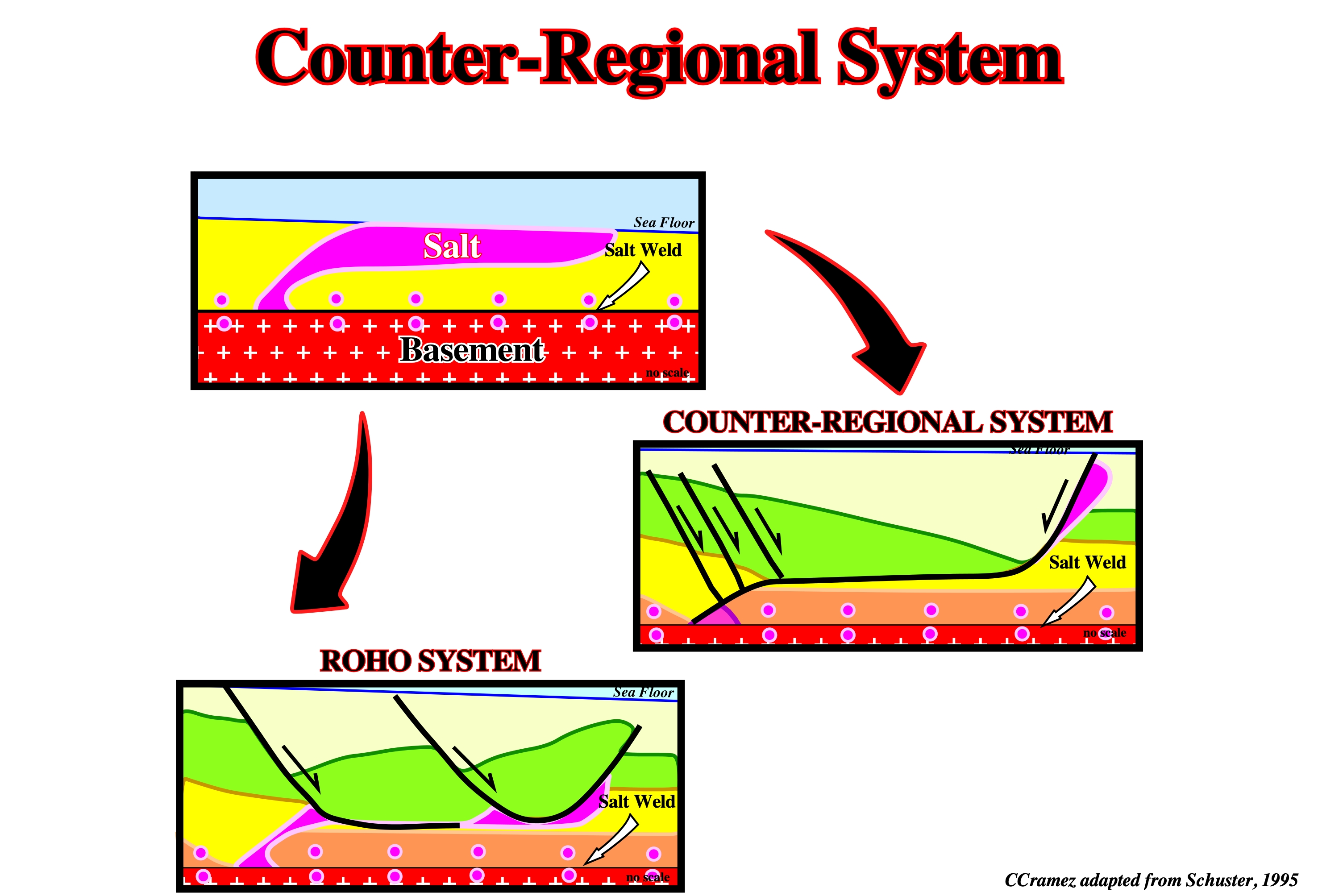
Schematic cross-section showing an allochthonous salt sheet and its ultimate evolution, following depositional loading and salt evacuation, into either of two end-member structural systems: (i) A stepped counter-regional system, consisting of a large growth fault looking landward, and (ii) A Roho system, dominated by a major growth faults looking seaward.

The Bourbon dome (southeast Louisiana), illustrated on this tentative geological interpretation of a Canvas autotrace of A GOM seismic line corresponds to a salt intrusion in a counter-regional faulting system and quite likely it soles in an evacuated salt horizon (tertiary salt weld ?). The depocenter associated with the counter-regional fault systems is quit evident on the hangingwall. All synkinematic layers thick toward the fault planes with northward vergence (continentward).
Cover
Sedimentary pile above the basement including both substratum (salt) and overburden.

The terms cover, basement and substratum are misleading. In salt tectonics, basement corresponds, often, to the infrasalt strata, substratum corresponds to the autochthonous salt and cover corresponds to the sedimentary pile including the substratum (salt) and the overburden. On this seismic line, it is quite evident that the basement, is not the real basement and the substratum (salt) is not the real substratum of the basin. Seems better to use these terms in their original meaning.
Craton
A part of the Earth's crust that has attained stability, and has been little deformed for a prolonged period. As originally defined, cratons included parts of both continents and ocean basins. Modern oceanographic studies indicates the unlikely existence of cratons in ocean basins. The term craton is now restricted to large continental areas of Precambrian age.
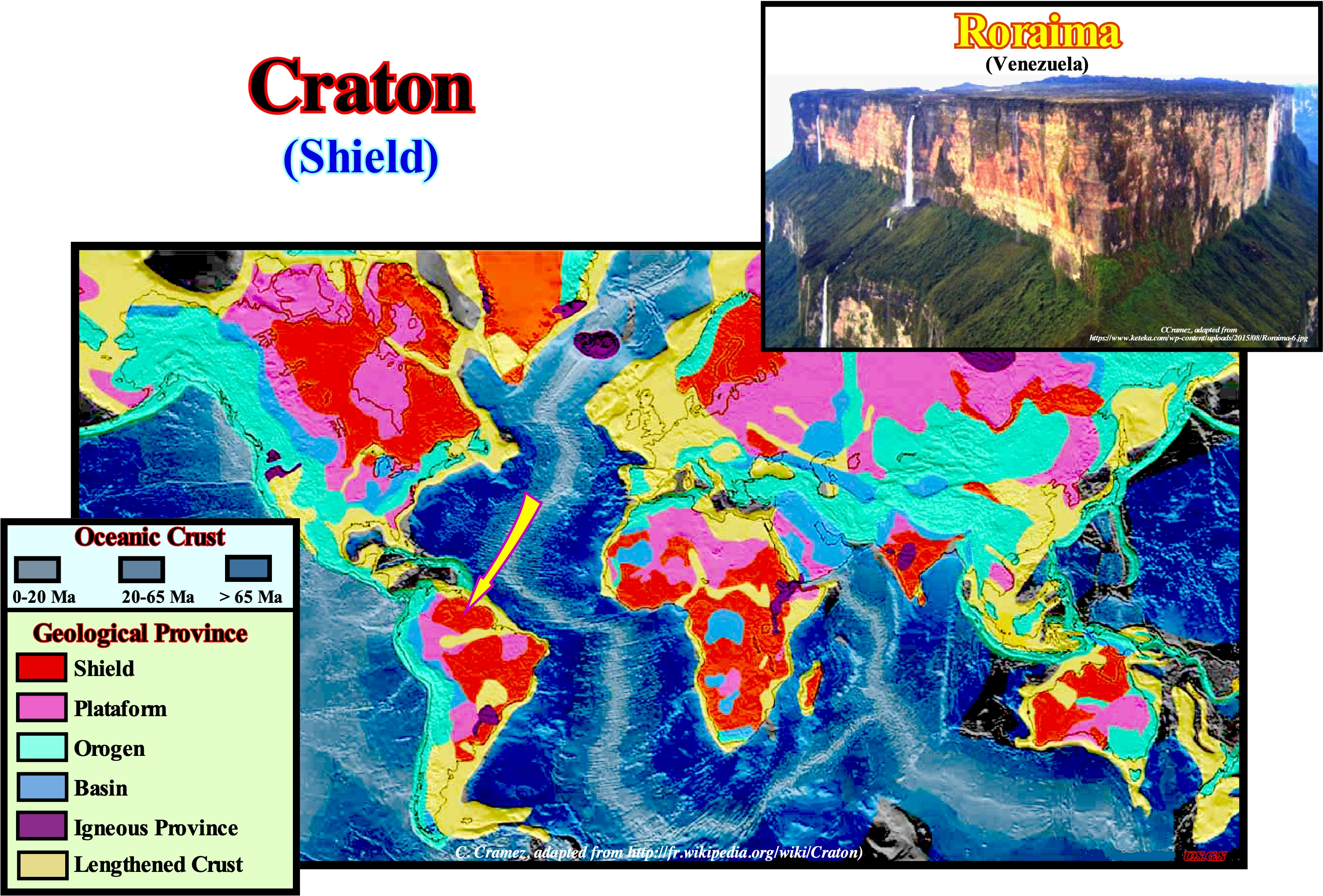
The extensive central cratons of the continents, including both shields and platforms, have been called hedreocratons. Part of the more mature Phanerozoic fold-belts have now achieved or are approaching a cratonic condition.
Creep Law for Halite
The creep law for halite is an expression to quantify the steady-sate flow of halite resulting from the combined effect of solution-transfer creep (dominant at low deviatoric stress and low strain rates) and dislocation creep (dominant at high deviatoric stresses and high strain rates). The strain rate can be approximated by following composite creep law : e° ={7.6 x 10⁻⁴ exp(-66,500/RT) σ4.5 } + {4.2 x 10⁻³ exp(-26,959/RT) σ /Td3}, where: e° is strain rate (s-1), R is universal gas constant (8.315 JK-1 mol-1), T is temperature (K), σ is deviatoric stress (Mpa; typically <3, and d is grain size (mm; typically 1-10 but smaller in extrusions).

Creep or cold flow is the tendency of a solid material, as for instance salt, to move slowly or deform permanently under the influence of persistent mechanical stress. Rock salt behaves as a visco-plastic material ; it has the tendency to creep when subject to stress. The creep strain rate is dependent on several factors: (i) Temperature, (ii) Differential stress, (iii) Confining pressure, (iv) Grain size, and (v) Presence of inclusions of free water or free gas bubbles. Temperature and stress differentials are the main drivers for salt creep. The tachyhydrite, for instance, which is a type of salt formation, is very weak in comparison to halite. It can develop a creep strain rate that is two orders of magnitude faster than halite for the same state variables, temperature, and stress. From a geomechanical point of view, salt creep is the rock deformation caused by the dissipation of strain energy generated by the stress relief in an undisturbed salt rock mass. In the context of a wellbore, creep closure may also provoke stuck pipe and casing collapse, creating significant difficulties for well construction and operations. Even though the creep process is slow. The well closure may still occur and eventually cause severe problems with casing failures in the salt formations , because of excessive stress that goes beyond the mechanic strength of the casing. A typical creep curve for salt rock consists of two or three creep stages. Following the application of the stress difference, the strain rate is, initially, significantly high. This high level of strain rate then decreases, monotonically, with time until a constant strain rate is observed. These two stages are, respectively, called transient and steady-state creep. Depending on the level of temperature and the differential stress applied to the specimen, a third stage, called tertiary creep, may become evident. This is characterized by acceleration of the creep strain rate caused by the specimen structure damage induced by the creep strain accumulation with time. At the tertiary creep stage, the dilation phenomenon, an increase in volume through micro-fracturing develops, leading to failure of the specimen. (https://hal.archives-ouvertes.fr/hal-01626417/document)
Crescentic Fold (Salt)
Fold with concentric axial trace and shallow-plunging fold hinge, originating inside the bulb of mushroom diapir.
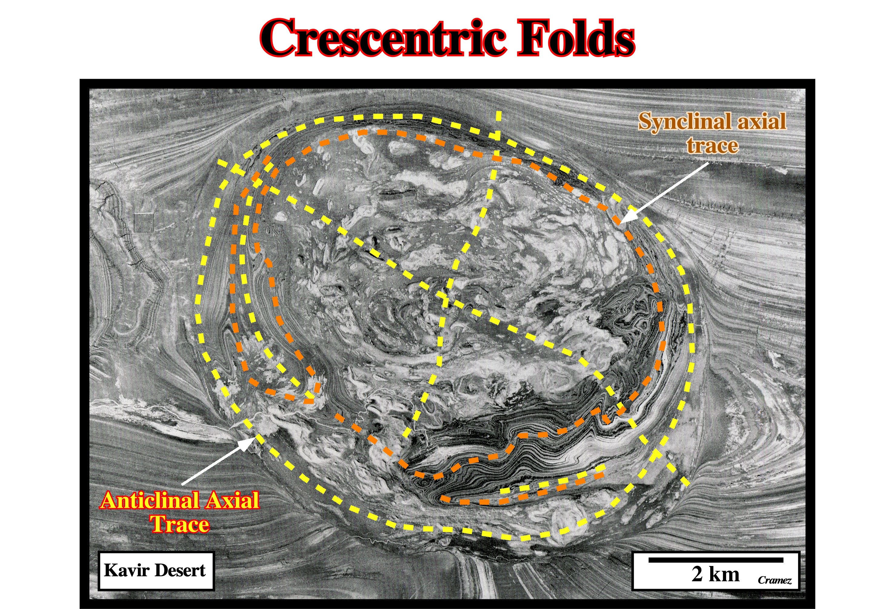
The concentric axial trace of the folds can be easily recognized on the field and on aerial photographs of Kavir desert.
Critical Coulomb Taper
The taper angle of an accretionary wedge, in which compressive forces at any point are balanced by frictional resistance of that part of the wedge ahead of that point.

A critical taper is the equilibrium angle made by the far end of a wedge-shaped agglomeration of material that is being pushed by the near end. The angle of the critical taper is a function of the material properties within the wedge, pore fluid pressure, and strength of the fault (or decollement) along the base of the wedge. The critical taper concept assumes mechanical equilibrium ( when the net force on a particle is zero and by extension, in a physical system made up of many parts is in mechanical equilibrium if the net force on each of its individual parts is zero), which means the compressional force (the push) that created the wedge will be equal to the resisting forces inside the wedge. Do not forget that the preliminary tentative geological interpretation done in a Canvas autotrace of a GOM seismic line is in time, and so the critical taper angle is, probably, quite exaggerated.
Critical Value (Rac)
The minimum Rayleigh number, above which thermal convection is possible.

Rayleigh's number (Ra) is a dimensionless number used in fluid mechanics and characterizing the heat transfer within a fluid: less than a critical value (Rac) of around 1,700, the transfer operates only by conduction, while beyond this value it is free or natural convection which becomes preponderant.
Curtain Fold (Salt)
A diapiric, cylindrical-fold with radial axial trace and steeply plunging hinge, which forms by constriction of the stem, possible incorporating sheath-folds originally formed in the source layer.

Cutaway diagram showing progressive deformation of a representative bed near the base of a salt source layer. As the bed flows toward the central stock, recumbent sheath-folds become folded and perhaps refolded above steps in the basement. The sheath-folds then rotate into the base of the salt stock, where they are refolded by steeply plunging curtain folds.
Cylindrical-Folds
A fold generated or reproduced by moving a line with fixed orientation through space. In structural geology a cylindrical fold strikes perpendicularly to the maximum effective stress (σ1) and, in a stereographic projection, the projection of the flanks (dip) lies on a meridian.
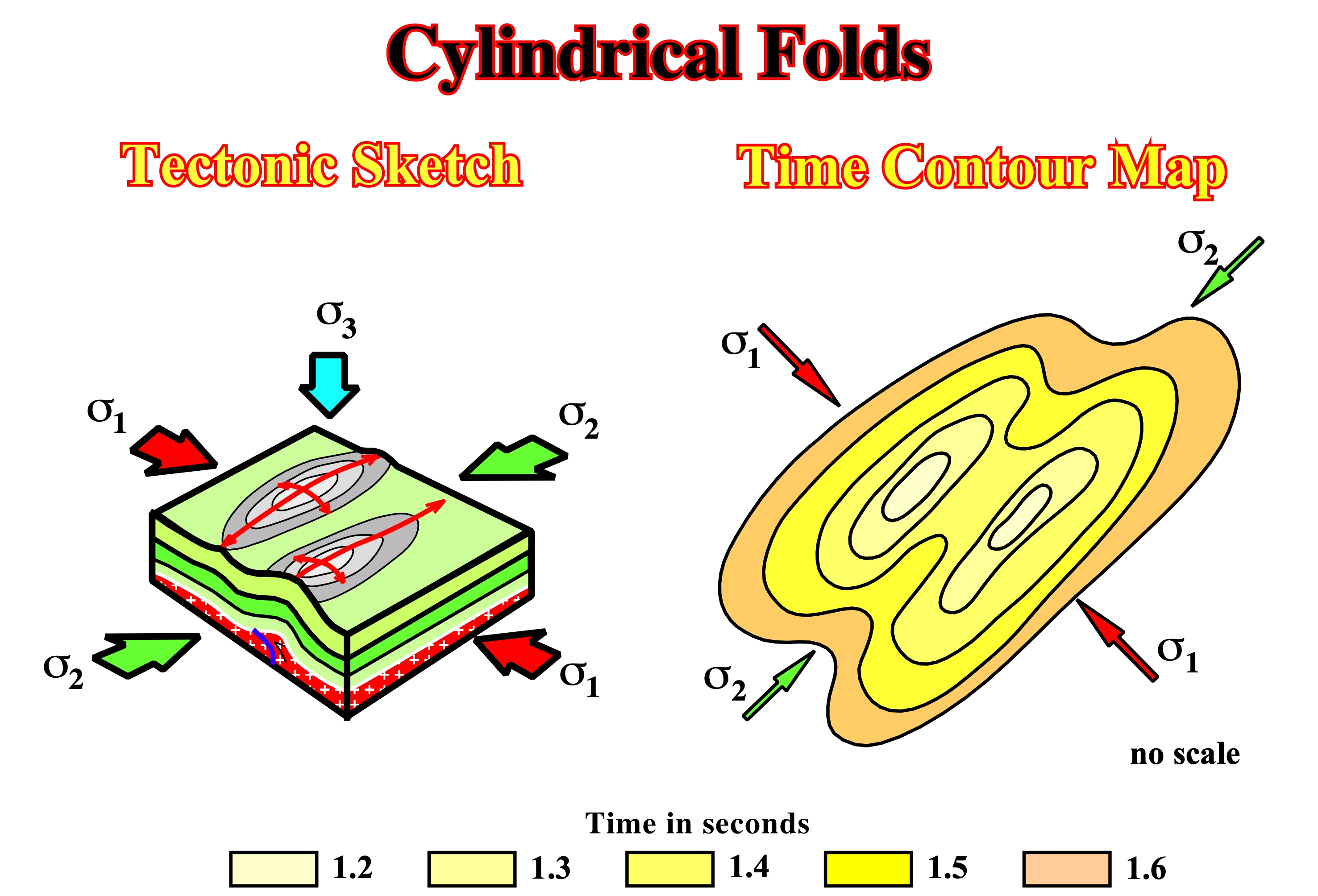
The axis of a cylindrical-fold gives the orientation in the horizontal plane of the medium effective stress (σ2). Similarly, all associated reverse and thrust-faults strike parallel to σ2.
Cylindrical Regime (Diapirs)
When in the evolution of a salt diapir the net rate R°/A° = 1 (flow rate of salt minus dissolution /rate of aggradation minus compaction) and the top salt contacts are molded such that they are, more or less parallel upward (molding models). The angle α° (salt/sediment boundary angle) is quite high approaching 90°.
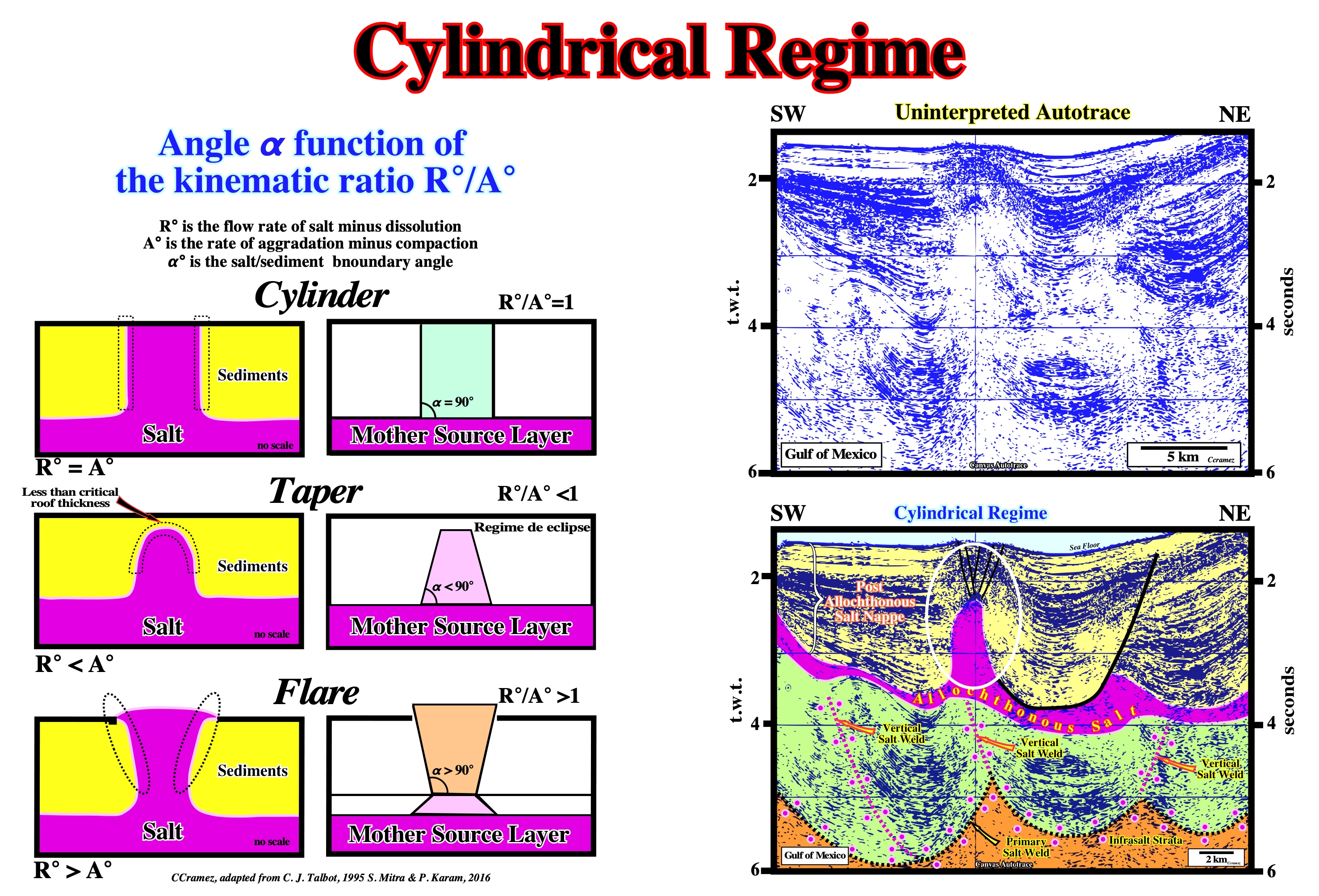
On this tentative interpretation of a Canvas autotrace of a Gulf of Mexico seismic line, the salt dome developed in the allochthonous salt growth during a cylindrical regime. The walls of the salt dome are quite dome are quite stiff, near of vertical. The kinematic ratio R° /A° is near 1. For those who difficulty to recognize the allochthonous salt, the primary salt weld and the associated vertical salt welds, please take a look at the geological evolution of a parallel autotrace illustrated on next figure.
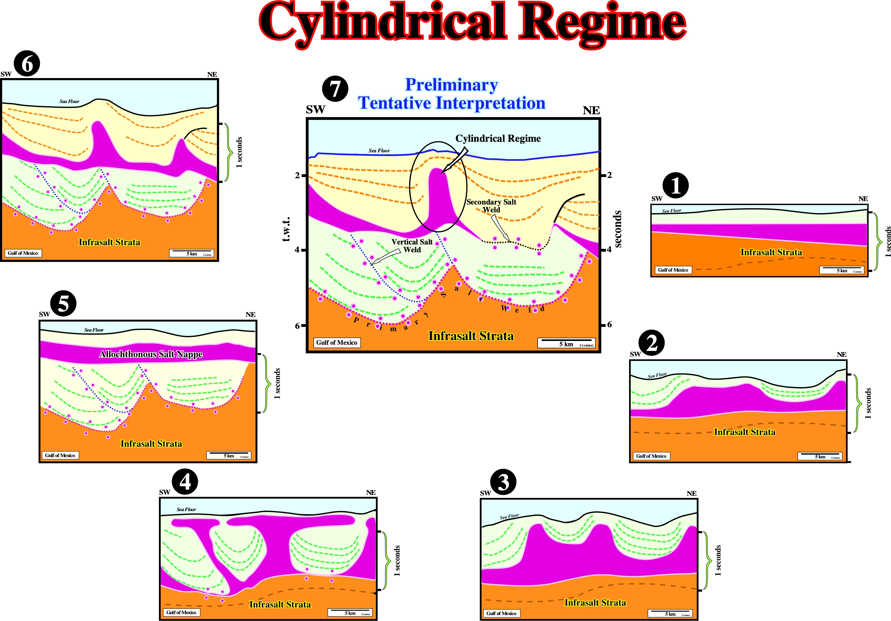
Starting with the preliminary geological tentative of a Canvas autotrace (7, parallel to the autotrace illustrated on previous figure, it is easy to recognize the infrasalt strata is limited by a primary salt weld. The vertical welds, along each the autochthonous salt flowed upward to create an allochthonous salt nappe, in which second generation salt domes (6 & 5), are easily recognized. The allochthonous salt nappe was the result of the coalescence of several salt canopies with salt sutures (4), which stem became vertical salt welds (5). Before the development of the salt canopies, several salt mound structures associated with the autochthonous were likely (3). The autochthonous salt started to form mound structures (2) sometime after the salt deposition (1).