
Daughter Diapir
A second-generation salt wall or stock flanking the mother diapir.
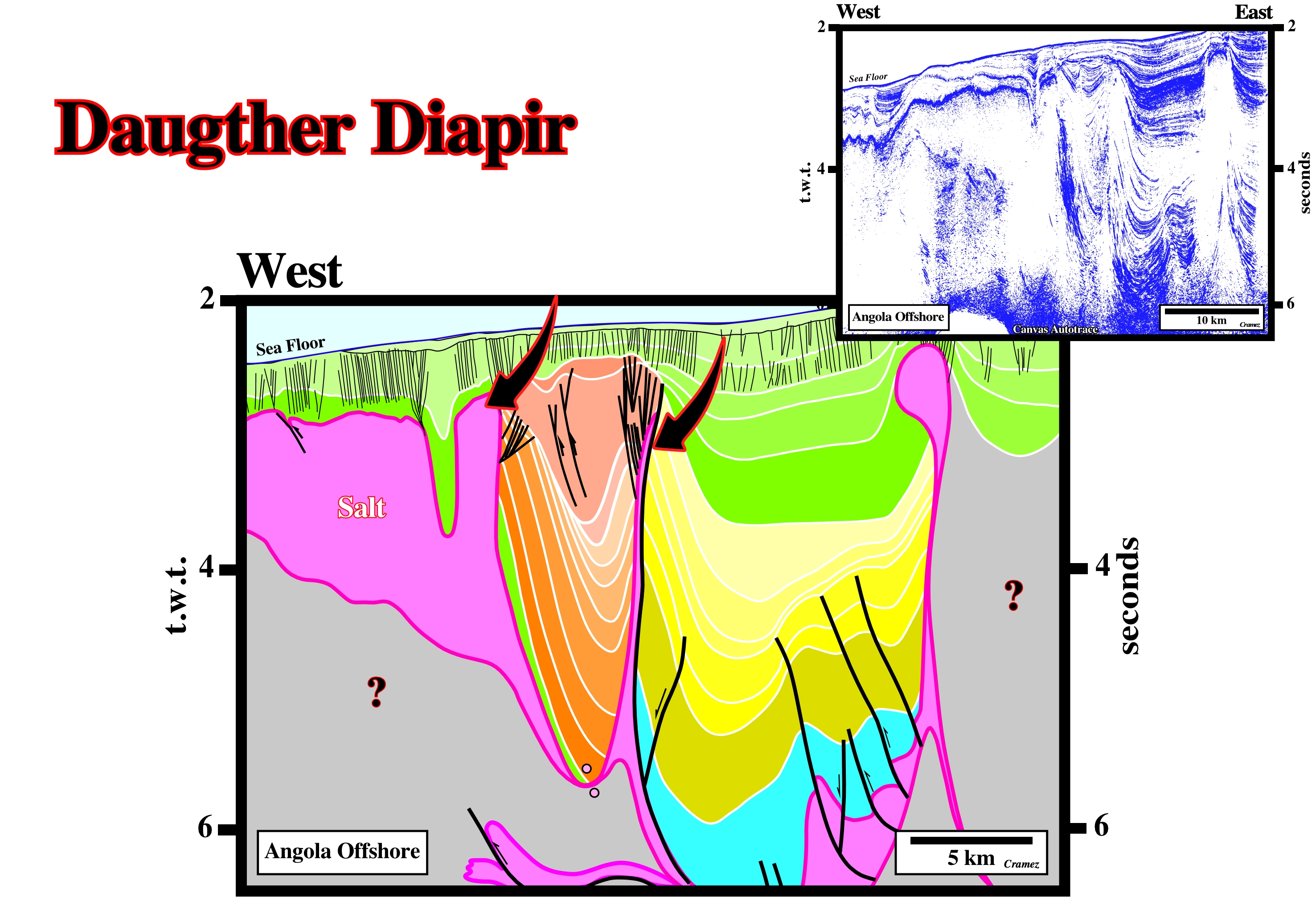
Daughter diapirs are frequent in Angola deepwater where allochthonous salt seems to be emplaced in association with a compressional tectonic regime created as a counterpart of an extensional tectonic regime developed up-dip.
Decaying Bulge
See Dynamic bulge.
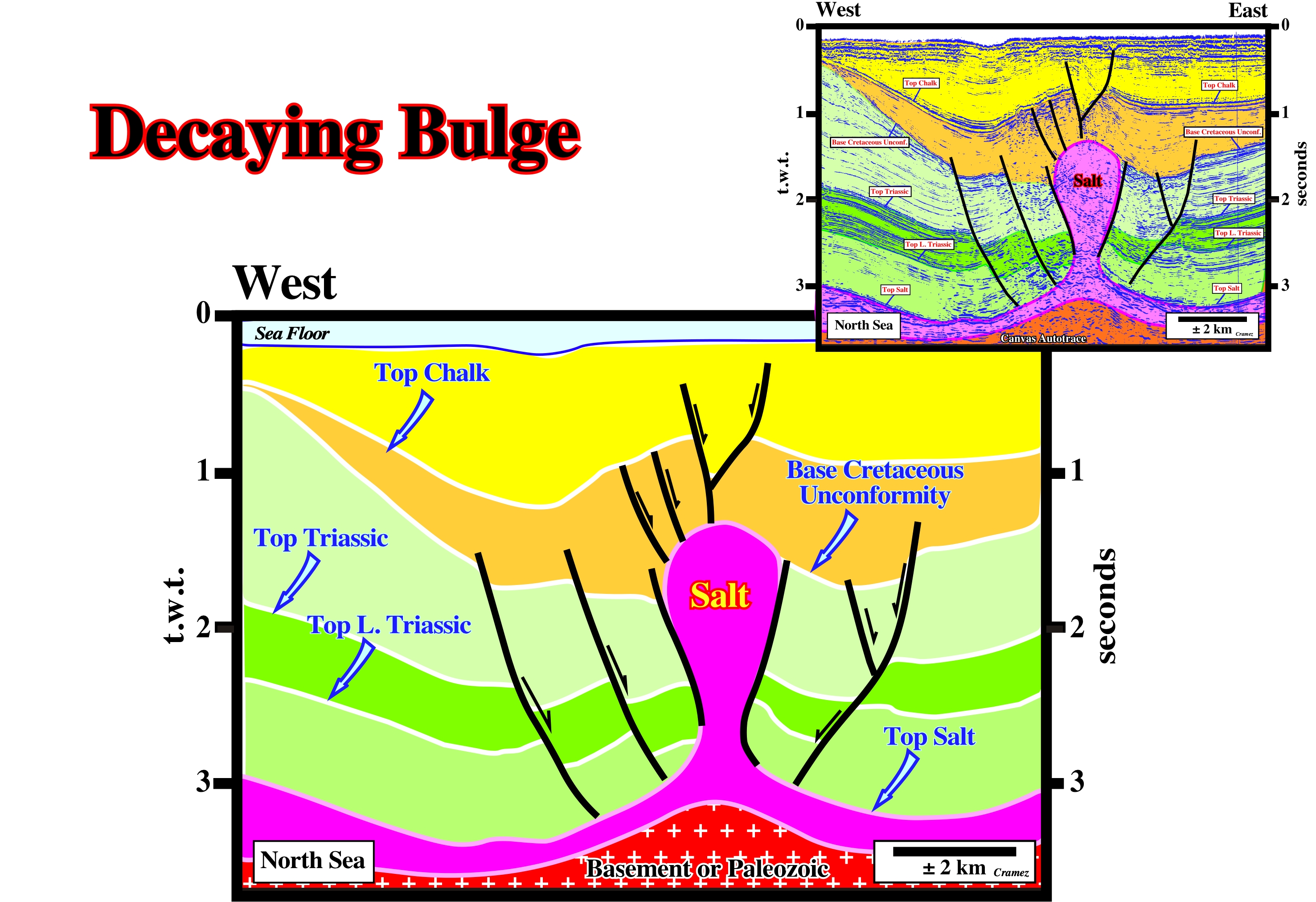
On this tentative geological interpretation of a Canvas autotrace of a North Sea seismic line, it is interesting to notice the depocenter of the light brown interval (base Cretaceous / Top Chalk) is inverted. That means during the Lower Cretaceous the salt dome collapse increased, locally, the space available to the Chalk deposits. Later, a compressional tectonic regime took place shortening the salt dome, as well as, the overburden, creating a nice inversion of the Chalk sediments.
Decollement
A soft or incompetent layer allowing deformation of the overlying strata to be decoupled from underlying rocks. This leads to an independent deformation above and below the decollement surface, i.e., the decollement surface induces a tectonic disharmony.

A major tectonic disharmony is, almost always, associated with a decollement. It was the recognition of such a tectonic disharmony that allowed, in the 60s, geologists working in Angola to advance the hypothesis that the disharmony was associated with an evacuated salt horizon, i.e, a salt weld. On this tentative geological interpretation of a Canvas autotrace of a Cabinda offshore seismic line, the sediments above the tectonic disharmony are quite deformed, while those located below are undeformed (the small undulation observed below the tectonic disharmony are pull-ups and pull-downs induced by the salt structures).
Dejective Fold Style (Stille, H., 1917)
Fold style recognized in the overburden of the Permian Zechstein characterized by narrow synforms and broad, flat-topped antiforms.
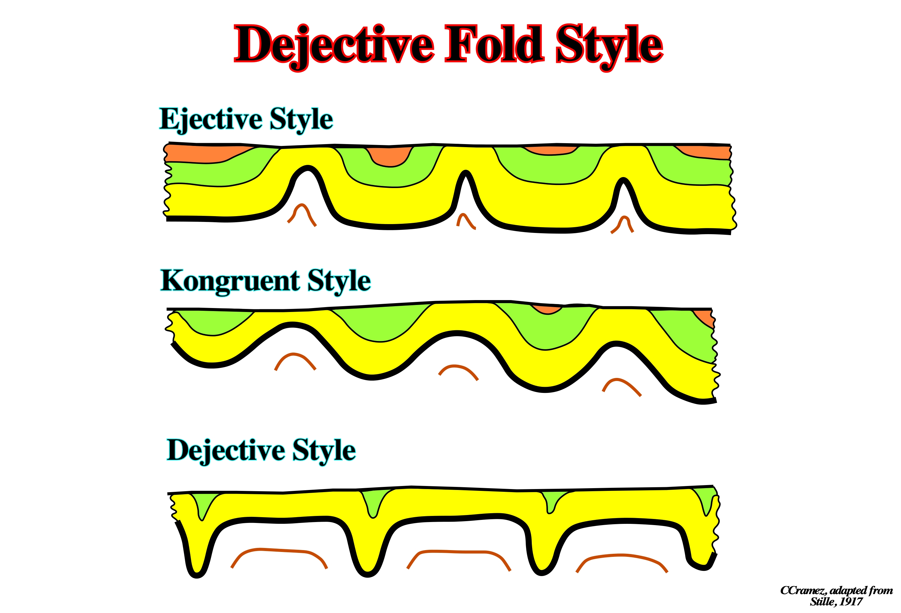
In 1917, in North Sea, Stille identified three major geometries of folds over the Permian Zechstein salt: (i) Ejective, characterized by narrow antiforms and broad, flat-bottomed synforms, (ii) Dejective, characterized by narrow synforms and broad, flat-topped antiforms, (iii) Kongruent, characterized by an intermediate geometry between the two end-members. All these folds are extensional structures developed in a association with a tectonic regime characterized by a σ1 vertical induced by the salt movements.
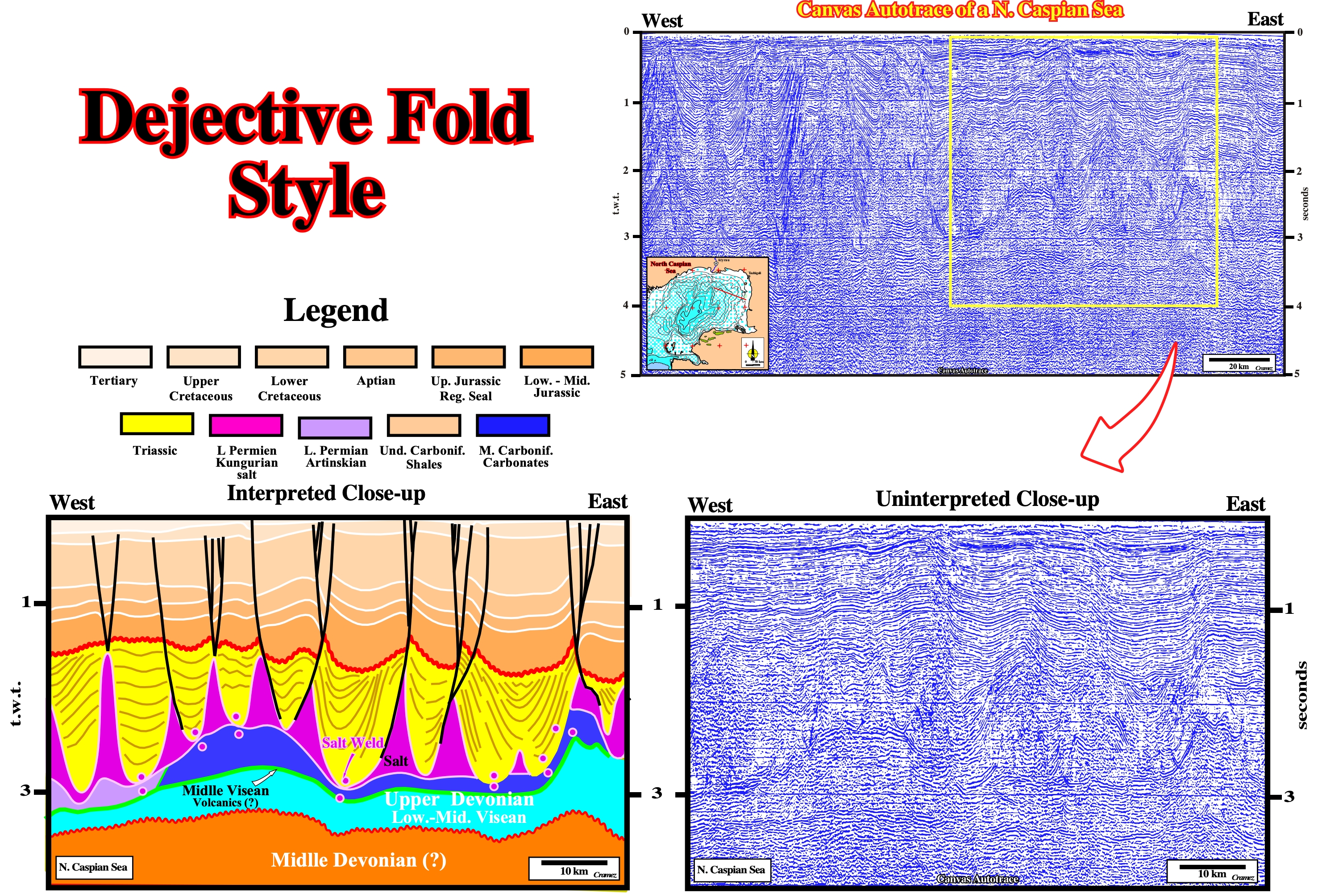
As illustrated on this tentative geological interpretation of a Canvas autotrace of a regional seismic line of the North Caspian Sea, the folds associated with the Kungurian Salt (Lower Jurassic) can be considered as dejective folds (Stille, H., 1917). The salt domes antiforms seem to be, relatively, wider than the synforms structures between the domes. During the post-Triassic, the dome structures seem to be reactivated, mainly, by faulting.
Delta Front (Bates, R. L. and Jackson, J. A., 1980)
A narrow zone where deposition, in a delta, is most active, consisting of a continuous sheet of sand, and occurring at the effective depth of wave erosion (10m or less).
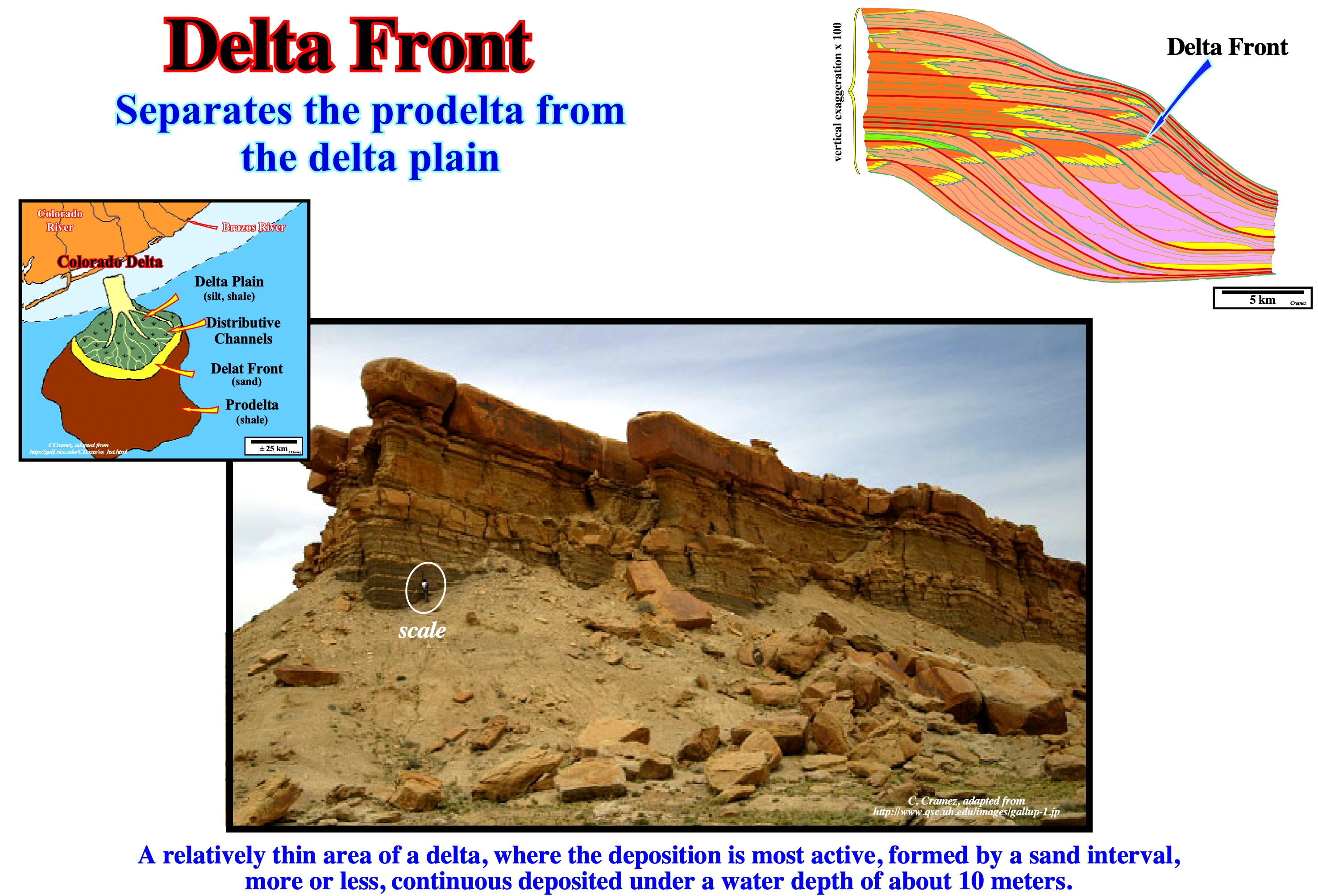
This photograph illustrates the sandstone intervals of a delta front, deposited during the Cretaceous in the New Mexico basin (USA). In sequential stratigraphy, a delta can be considered as a sequence-paracycle, i.e., as a lateral association of depositional systems (lithology with an associated fauna). A lateral chain of contemporary depositional systems forms a sedimentary systems tract. A sedimentary systems tract corresponds, in general, to a sequence-paracycle, limited between two flooding surfaces. Depositional systems are used to subdivide, correlate and map synchronous rocks (which are deposited at the same time) which are, genetically, related, i.e, if a depositional system of a sedimentary systems tract is not deposited, the other systems, usually, are, also, not deposited. A vertical and progradational stacking of a delta sequence-paracycle form a subgroup of either highstand systems tracts, as for instance, the transgressive interval (TI) or lowstand, as the lowstand prograding wedge (LPW). In sequential stratigraphy, a delta corresponds to a sequence-paracycle deposited during the period of stability of the relative sea level occurring after the marine ingression (eustatic paracycle) that created the space available for sediment (shelfal accommodation). The geological model (upper right corner), was made with the help of P. Vail, during a trip to Balikppan (Borneo, Indonesia), to express that in a delta, from the continent seaward, four depositional systems (set of lithologies and associated, generally, with a characteristic fauna) are, often, recognized: (i) Siltstones of the delta plain ; (ii) Sandstones of the delta front ; (iii) Claystones of the prodelta and (iv) Claystones or sandstones (proximal turbidites) at base of the prodelta. In terms of original structural behavior, the strata of the delta plain and the delta front are, practically, subhorizontal. The prodelta strata are deposited with a seaward well-marked dip, while the shales or sands of the base of the prodelta are, more or less, subhorizontal. The delta front corresponds, more or less, to the slope break of the depositional surface between the delta plain and the prodelta. The dipping layers of the prodelta can extend, more or less, horizontally to the continental shelf, forming what certain geoscientists call the lower subhorizontal delta layers, in opposition to the upper delta layers located upstream of the prodelta. In certain cases, when the dip of the prodelta strata exceeds the critical angle (stability angle of the prodelta), subhorizontal lobes of turbidite origin (proximal turbidites of Shell) can be deposited at the base of prodelta progradations. Although deltas are more frequent in sequence-paracycles of the highstand systems tracts (mainly in highstand prograding wedge), they can also be deposited under lowstand geological conditions in the lowstand prograding wedge (LPW). A delta should not be confused with a delta building. A delta (sequence-paracycle which corresponds, sometimes, to a single sedimentary systems tract) has, generally, a thickness lower than 60 meters. A delta building, which is a stacking of deltas, that may belong to different systems tracts subgroup of a sequence-cycle or of different sequence-cycles, can reach thicknesses of several kilometers. Do not say Niger delta (which does not exist), but rather Niger delta building. On the other hand, do not forget: (a) Under normal conditions, a delta is not deposited during a relative sea level rise, as many people think, but during period of stability of the relative sea level following the marine ingression ; (b) The relative sea level is the local sea level referenced to the base of the sediments (top of the continental crust) or the sea floor ; (c) The relative sea level is the result of the combined action of the absolute (eustatic) sea level (referenced to the Earth's center) and tectonics (subsidence or uplift of the sea floor) ; (d) The absolute sea level is dependent on: 1) Tectono-Eustasy, controlled by the volume variation of the ocean basins in association with oceanic expansion following the break-up of the supercontinents ; 2) Glacio-Eustasy, which is controlled by the variation of ocean water volume as a function of the amount of ice ; 3) Geoidal-Eustasy which is controlled by the distribution of ocean water caused by variations in the terrestrial gravity field, and 4) Thermal expansion of the oceans or Steric sea level rise.
Deltaic Environment
A geographical restricted complex area, where deltaic sediments accumulates, described in geomorphological terms and characterized by physical, chemical, lithological and biological conditions pertaining to or associated with a delta.
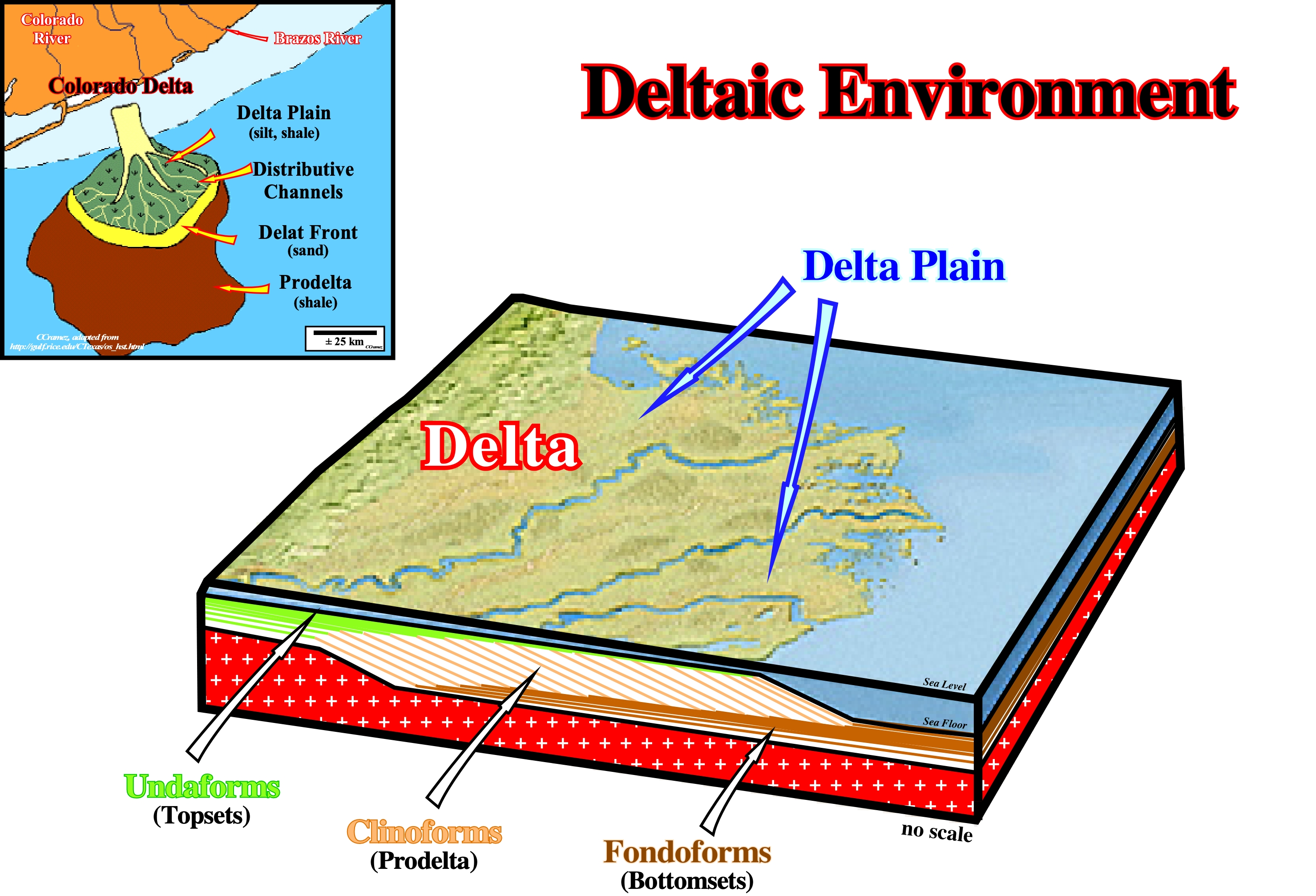
Deltas characterize deltaic environments. Deltas are low, nearly flat, alluvial tract of land at or near the mouth of a river, commonly forming a triangular or fan-shaped plain of considerable area. A delta is crossed by many distributaries of the main river, perhaps extending beyond the general trend of the coast. A delta is the result of the accumulation of sediment supplied by the river in such quantities that it is not removed by tides, waves and currents. Most deltas are, partly, subaerial and, partially, under the water. A delta has a thickness ranging from a few meters to several tens of meters. A delta building (stacking of several deltas), such as the Niger delta building, can reach thousands of meters. Taking into account the dominant forces in the formation process, Galloway classified the deltas into three main types: (i) River Dominated Deltas, characterized by strong terrigeneous influx of the rivers ; (ii) Wave Dominated Deltas, characterized by an high the activity of sea-waves and (iii) Tidal Dominated Deltas characterized by tidal activity and tidal currents.
Density Inversion
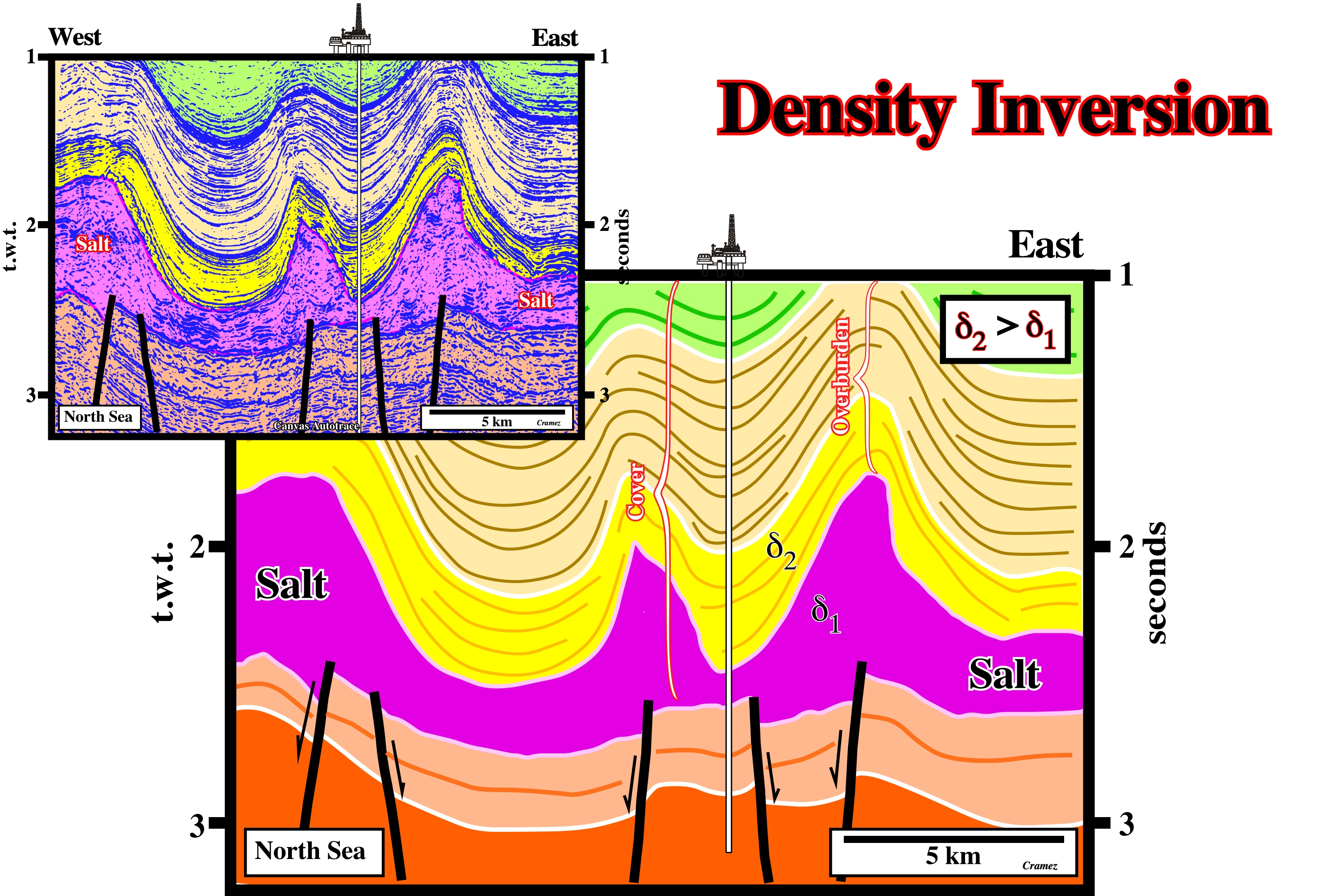
A superposition of a denser sedimentary layer above a less dense layer. In a salt basin, along a salt dome there is always a density inversion below the inversion point. Above the inversion point, the density of the salt, which cannot be compacted, is higher than the density of the sediments. Below the inversion point, as the density of the salt does not increase in depth, the density of the salt is lower than the density of the sediments.
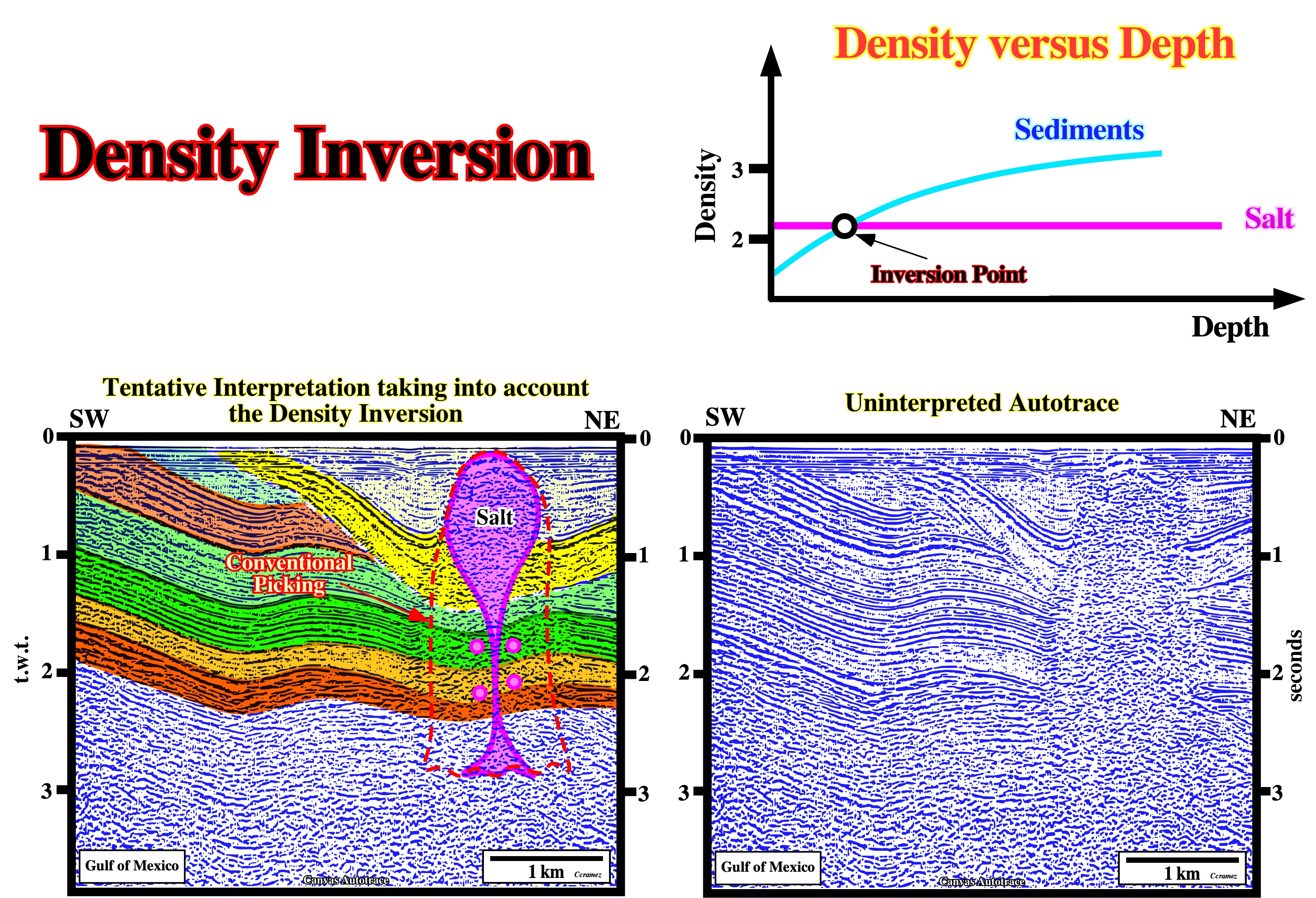
Theoretically, in a salt diapir there is always an inversion point. Above the inversion point, the pressure of the sediments against the salt of the diapir does not balance the pressure of salt against the sediments. Contrariwise, below the inversion point, as the density of sediments is higher than the density of the salt, the pressure of the sediments against the salt is much higher than the pressure of the salt against the sediments. As illustrated in the diagram, the density of the salt is, more or less, constant ranging between 2.15-21.7 (depending on the amount of magnesium). The density of the sediments increases, progressively, in depth. The intersection point of the salt and sediments density curves gives the depth of the inversion point. Below the inversion point the density of the salt is lower than the density of the sediments, above the inversion point is the contrary, the salt is denser than the sediments. On the above example (Canvas autotrace of a GOM seismic line), the proposed geological interpretation is based in the conjecture that a density inversion point exist along the walls of salt dome and so their verticality is a physical impossibility. The apparent verticality observed on the uninterpreted Canvas autotraces (on the right) is due to the fact that the cap rock and salt bulb absorb almost all energy of the seismic waves, which can not penetrate into depth. Under the cap rock there is any seismic reflector (reflection free internal configuration).
The Cretaceous lengthening that took place in southern North Sea, is, partially, due toe the density contrast between the salt layer and the overburden. At a certain depth, the density of the salt is lower than the density of the overburden, so, the salt starts to flow upward developing a lengthening of the sediments of the cover (salt + overburden). A tectonic disharmony exists at the bottom of the salt layer. The presalt strata is much less deformed. In fact, on this tentative geological interpretation, the slightly deformed subsalt strata (lengthened by normal faulting) contrasts, strongly, with the high deformation of the cover, in which synforms and antiforms are paramount. Do not forget to take into account the seismic pitfall induced by the lateral changers of the salt thickness. In a depth version of the original seismic line, the bottom of the salt layer is, more or less, subhorizontal ands not undulated.
Density of the Salt
Ranges between 2.15 and 2.17 depending of the composition.
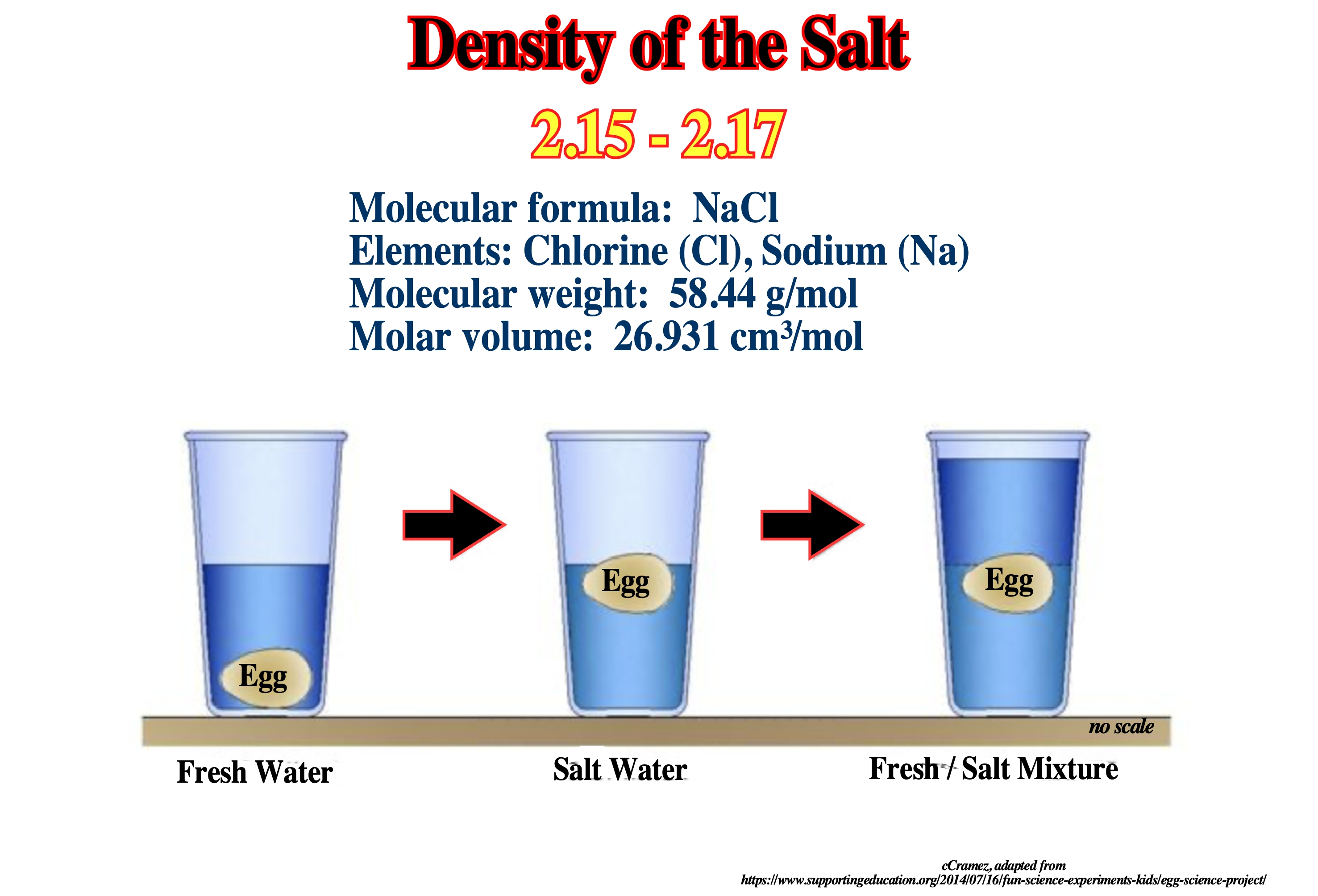
Common salt weighs 2.17 gram per cubic centimeters or 2, 170 kilogram per cubic meter, i.e. density of common salt is equal to 2, 170 kg/m³, at 25°C (77°F or 298.15 K ) and at standard atmospheric pressure. In Imperial or US customary measurement system, the density is equal to 135.469 pound per cubic foot [lb/ft³], or 1.25 ounce per cubic inch[oz/inch³].
Depocenter
An area or site of maximum deposition. The thickest part of any specified stratigraphic unit in a depositional basin.
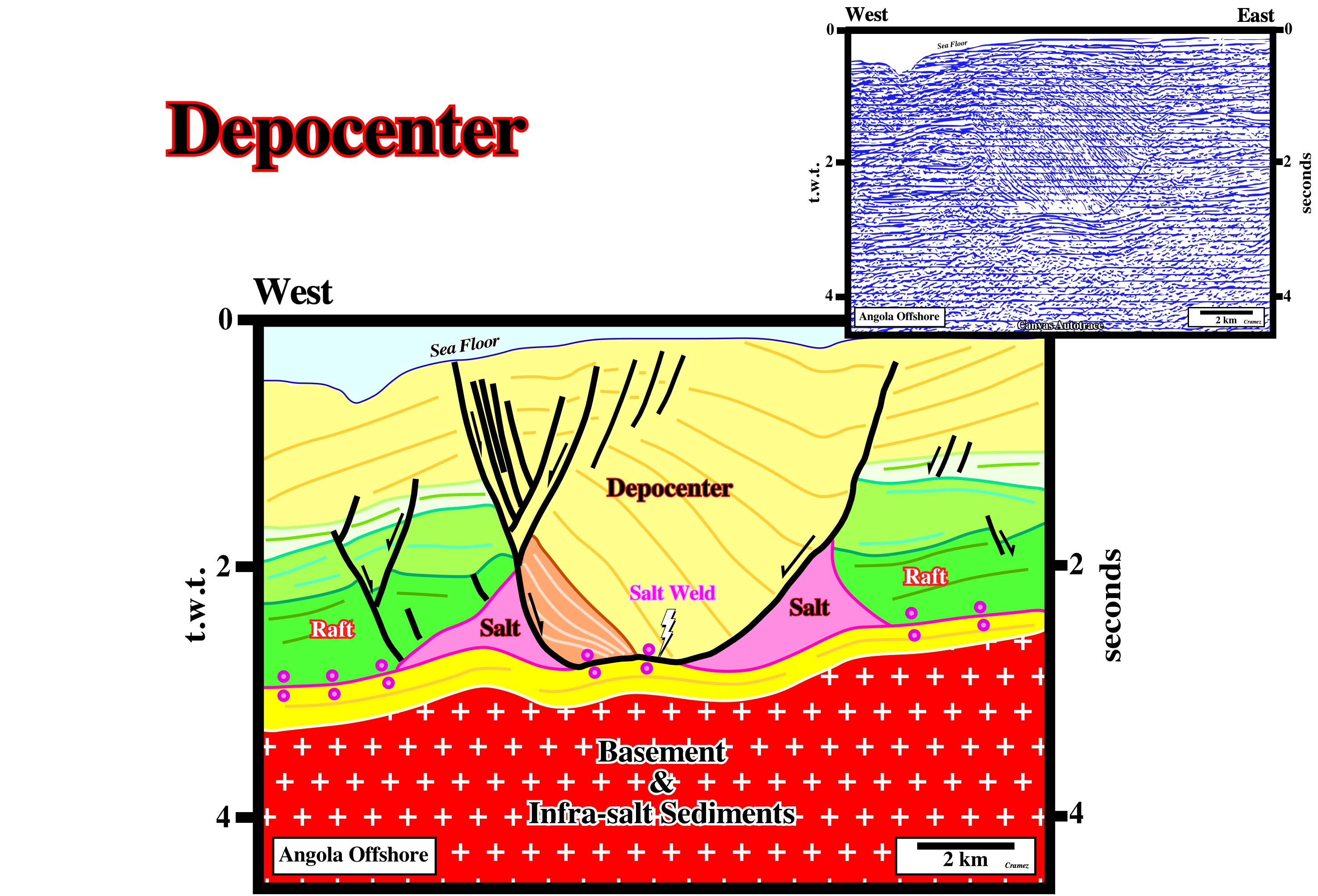
The internal configuration of the stratigraphic interval filling the yellow depocenter, located in the middle of this tentative geological interpretation of a Canvas autotrace of an Angola offshore seismic line, suggests a compensatory subsidence was created by an almost complete down-dip salt evacuation of a salt dome. Two relict salt structures are, easily, recognized up-dip and down-dip of the depocenter. At the bottom of the depocenter, the brown interval has an internal configuration showing an inward thickening suggesting it was deposited in a small pod on the top of the pristine salt dome. Primary salt welds are recognized at the bottom of the depocenter and in left and right ends of the autotrace.
Depopod
A salt expulsion basin subsiding into salt masses in shallow water, typically containing deltaic deposit, the sandiest parts of which drape over or against the flanking salt diapirs.
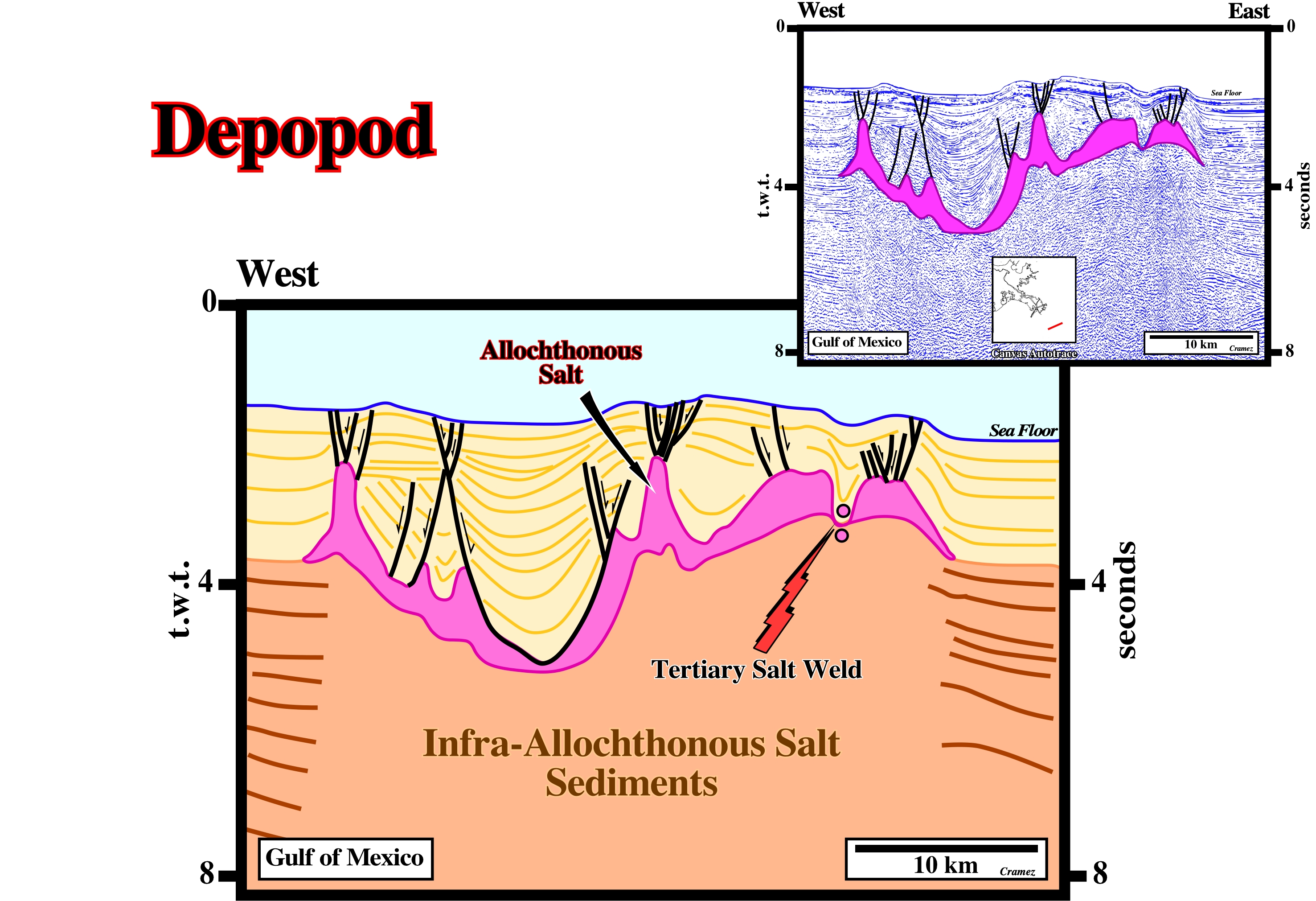
If the deepest parts of the mini-basins, recognized on this tentative interpretation of a Canvas autotrace of a Gulf of Mexico seismic line, were filled by deltaic sediments, then, at the time of the filling, the salt structures could be considered as depopod. Later, it is quite sure they evolved into typical mini-basins (or salt expulsion basins), which were, progressively, filled by deepwater sediments as they buried. The allochthonous salt structure absorb almost all energy of the seismic waves and so any really seismic reflection exits below it.
Depositional Coastal Break
See: Shelf Break
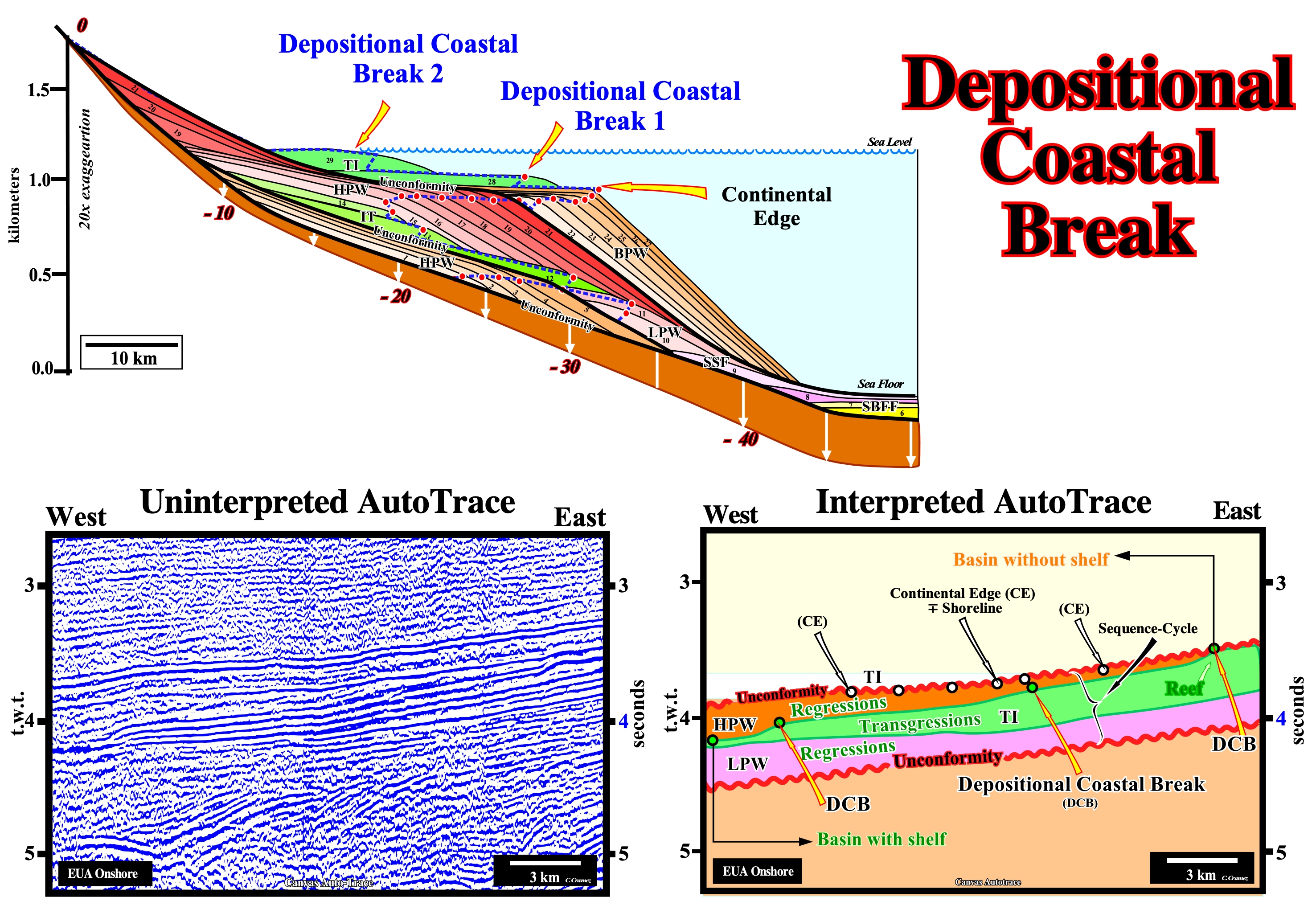
On this tentative geological interpretation of a Canvas autotrace of a detail of an United States onshore seismic line, several depositional coastal breaks of successive depositional surfaces are recognized. Within the considered sequence-cycle (bounded between two unconformities with a age difference not greater than 3-5 My), which was induced by a 2nd order eustatic cycle, some of depositional coastal breaks are associated with the transgressive interval (TI, colored in green) which has a well-marked retrogradational geometry (the thickness of the interval increases eastward, i.e., continentward). The first slope break of the transgressive interval, which marks the continental edge of the lowstand prograding wedge (LPW), before the first transgressive surface, is outside the autotrace (it is located westward, where, practically, the transgressive interval disappears). Three other depositional coastal breaks of successive depositional surfaces are, perfectly, visible within the transgressive interval. The younger is enhanced by the presence of a reef buildup). During the transgressive interval (TI), the shoreline, at the end of each sequence-paracycle (sedimentary interval deposited during an eustatic paracycle and bounded by two successive flooding surfaces, i.e., between two successive marine ingressions), moves continentward, further and further away from the basin edge (located westward of this autotrace) increasing the extent and the water-depth of the new shelf. During the overlying highstand prograding wedge (HPW), the toplaps of the progradations underline the successive positions of the depositional coastal breaks (corresponding, more or less, to the shoreline), which move, progressively, seaward. Only the 1st phase of development of the highstand prograding wedge (during which the basin has a shelf) is visible on this autotrace. These progradations corresponds to delta slopes. They are oblique progradations (seismically, there is no significant aggradation). They correspond to barrier bars deposited in association with deltas developed under the influence of waves, which strongly suggests throughout the highstand prograding wedge (HPW), the basin had no shelf.
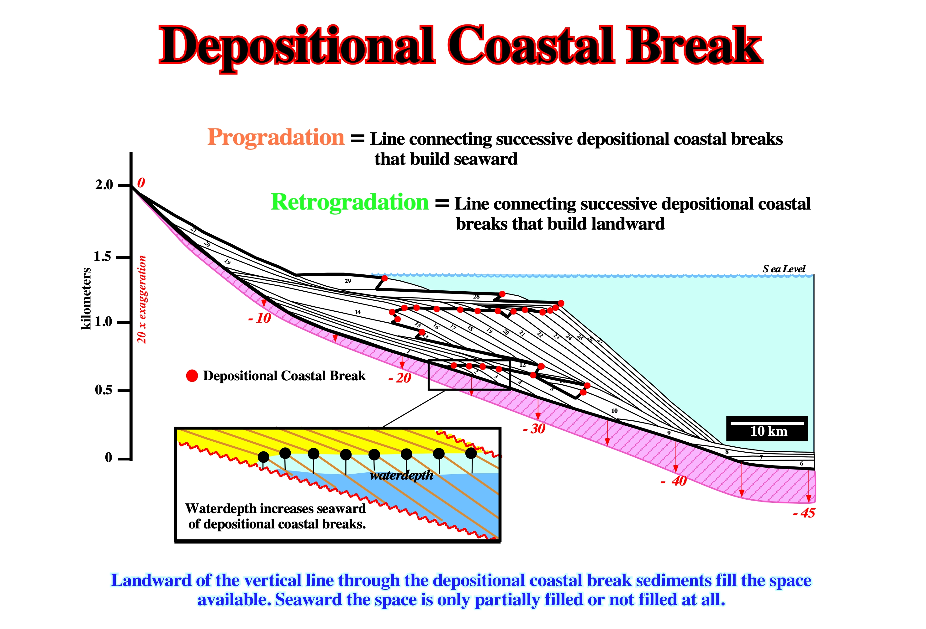
The picking of depositional coastal breaks, roughly, the landward limit of the delta front, allows to individualize transgressive (backstepping) from regressive episodes, which are characterized by a forestepping geometry. As the water-depth in the delta front is almost zero, the loci of the successive depositional coastal breaks allow to determine the water-depth seaward of the coastal break, as illustrated on the close-up.
Depositional Rate
The amount of sediment accumulated in an aquatic environment over a given period of time, usually, expressed as thickness of accumulation per unit of time. Depositional rate is a synonym of rate of sedimentation. However, as suggested by Sadler (1981), one should never forget stratigraphic sections are local archives of the geologic history. The records of these archives are the sedimentary beds deposited, in sequence, and which are, mostly, numbered according to their thickness rather than their time of deposition. Briefly speaking, depositional rates must take into account the completeness and preservation of stratigraphic sections.
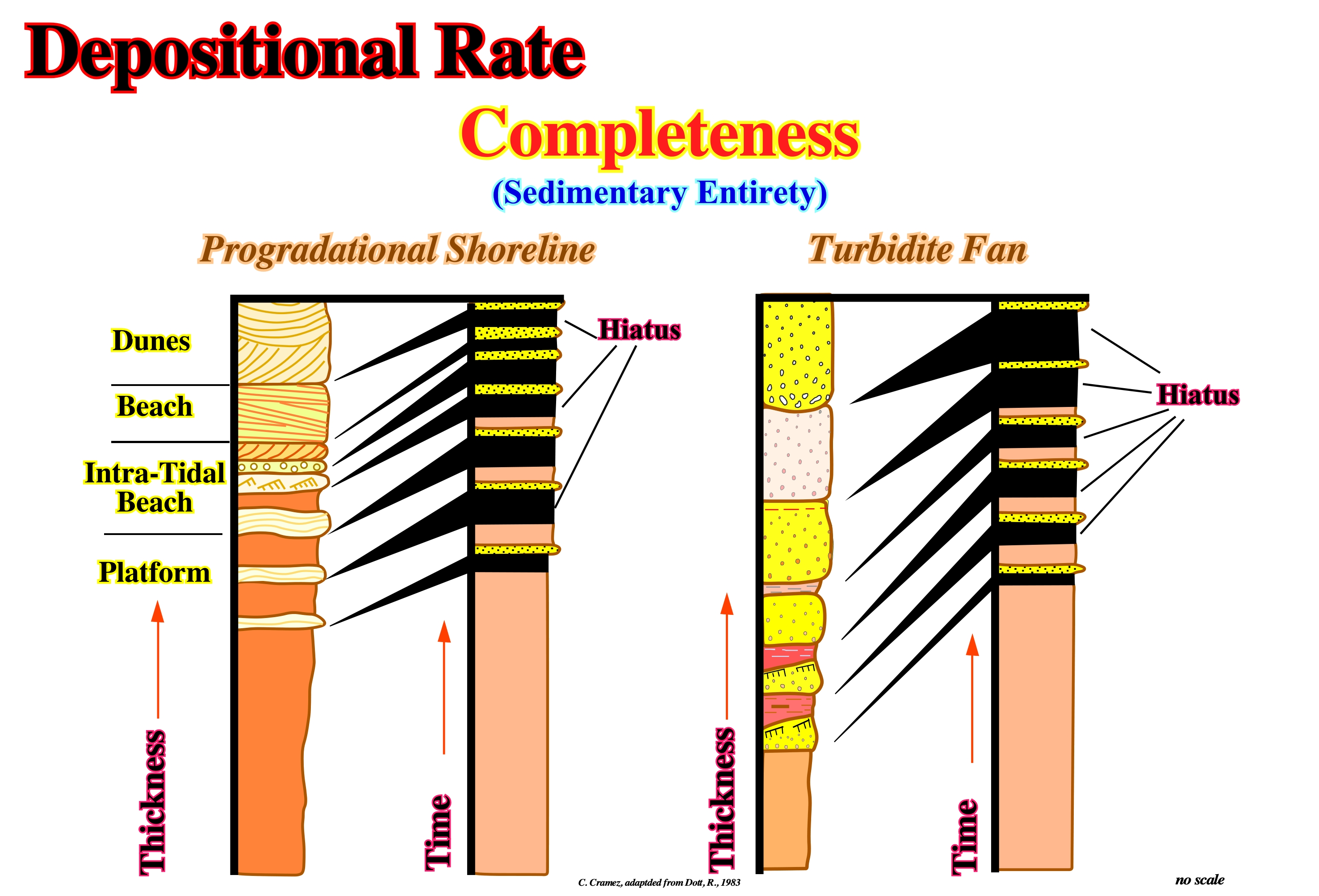
In these two stratigraphic models, it is important to notice, in the upper part of both sections, the time-duration of the periods of non-deposition is greater than the deposition time-duration. Most of the geologic events, which took place during deposition periods are not preserved. Therefore, the completeness (effective deposition time versus the total time of stratigraphic section) and preservation of stratigraphic sections must be taken into account when assessing depositional rates.
Depositional Sedimentation Level
Roughly, the effective depth of wave erosion (10 m or less), particularly in shallow water deposition or, in other words, the surface to which sediment accumulation fills up to or erodes down to, which is related to continental erosion. The depositional sedimentation level is a dynamic surface controlled by erosion, sediment deposition, tectonic movement and eustasy.
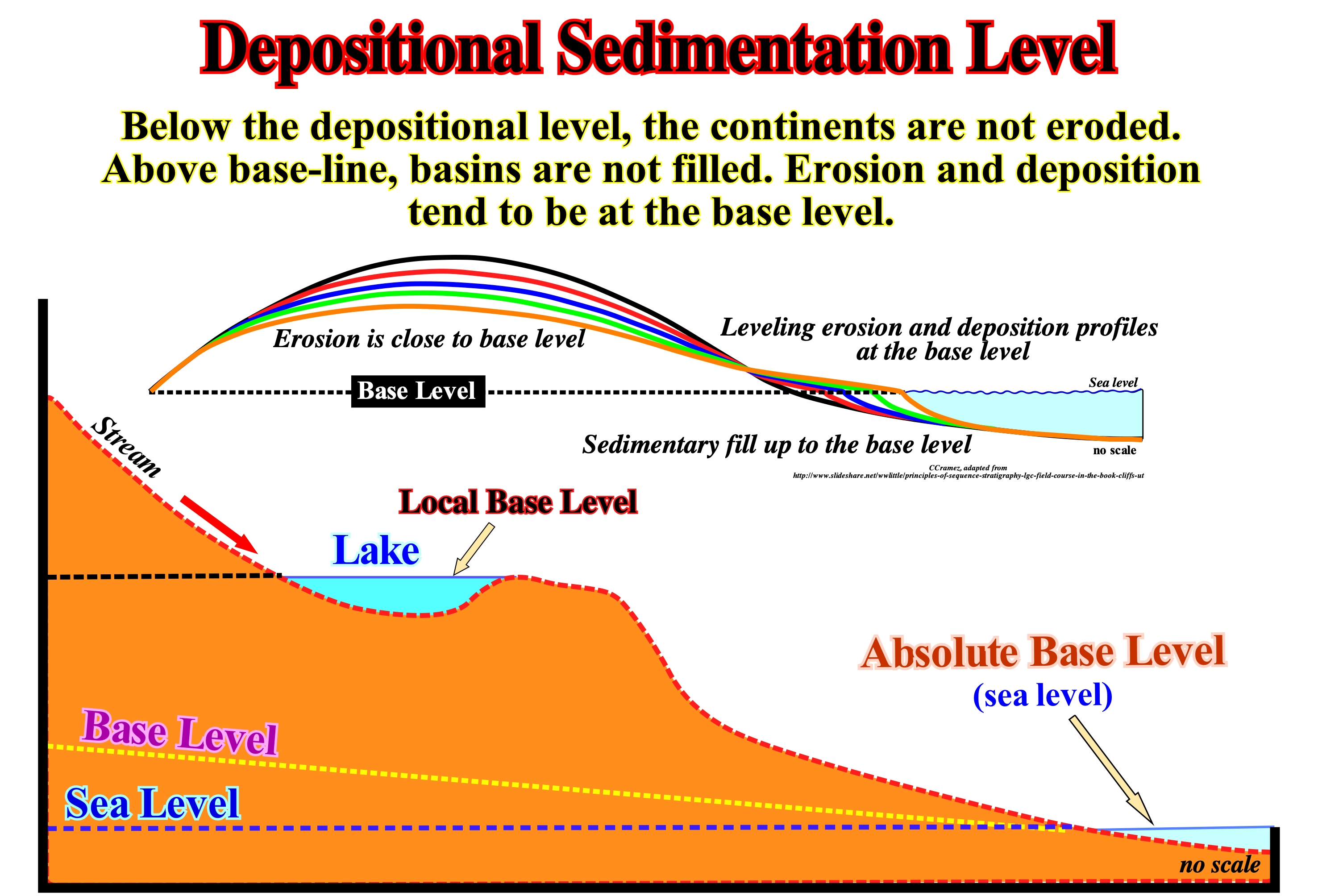
The depositional sedimentation level or base level of a current is the lowest point of the current beyond which the current can no longer erode. When a current reaches its base level, its kinetic energy is, practically, zero. As illustrated in this figure, the base level of a current may be represented by: (i) A lake, in which case the base level is temporary or (ii) The sea (in this case, the base level is definitive). The base level is, more or less, associated with the longitudinal profile of the water-course. When the current is young, the profile corresponds to a concave line upwards. I represents, more or less, the irregularities of the current bed, which means the profile of the current is not in equilibrium once the current is, continuously, eroding. When the current reaches a maturation stage, its longitudinal profile is, relatively, abrupt in the upper sector of the current. In the middle sector, it is a curved and concave upward and ends near the mouth by being horizontalized. Theoretically, since a current reaches its longitudinal equilibrium profile the current does not erode any more, which many geoscientists consider an utopia. For them, an equilibrium profile is always provisional. Without much error, in general, the base level of a current is, more or less, the sea level. In reality, it is, usually, a little lower due to the action of waves and coastal currents. The continuation of the base level continentward defines the final level of denudation. However, it should not be forgotten the base level of a current changes with the position of the relative sea level (the result of the combination of tectonics (subsidence or uplift of the sea floor) and absolute sea level (supposed global and referenced to the Earth's center).
Depotrough (Spindler, 1977)
A salt expulsion basin subsiding into or between thick salt masses in deep water, typically containing mass-flow or turbiditic deposits, whose sandiest part lie in uplapping configuration in the center of the depotrough. Synonym of depocenter in salt expulsion basins.
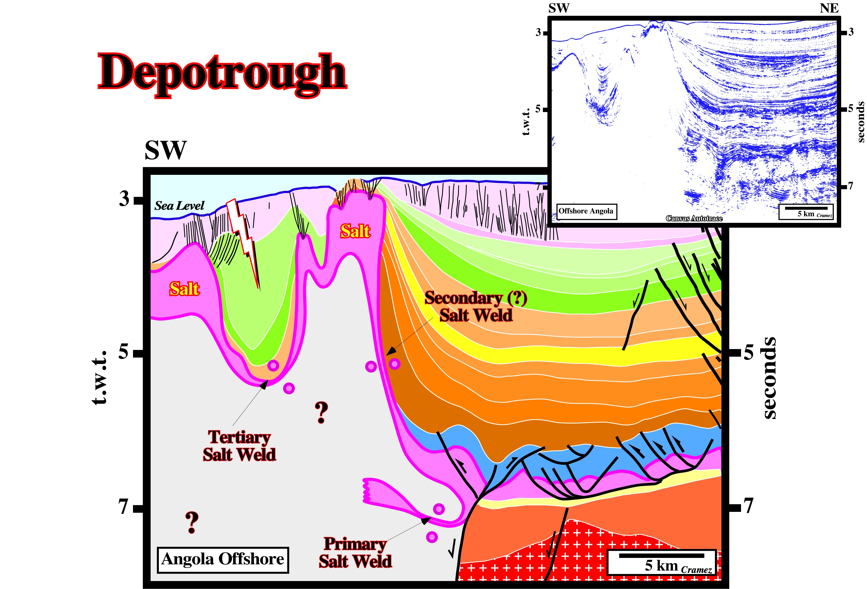
On this tentative interpretation of a Canvas autotrace of an Angola offshore seismic line, the mini-basin looks more a depotrough, with turbidite deposits at the base, rather than a depopod. In fact it is difficult to hypothesize the presence of deltaic deposits at the base of the mini-basin knowing the geological history of the area and the present water-depth (more than 3.0 seconds t.w.t.).
Detached Salt Stock
Pluglike salt diapir with subcircular planform detached from the mother salt layer.
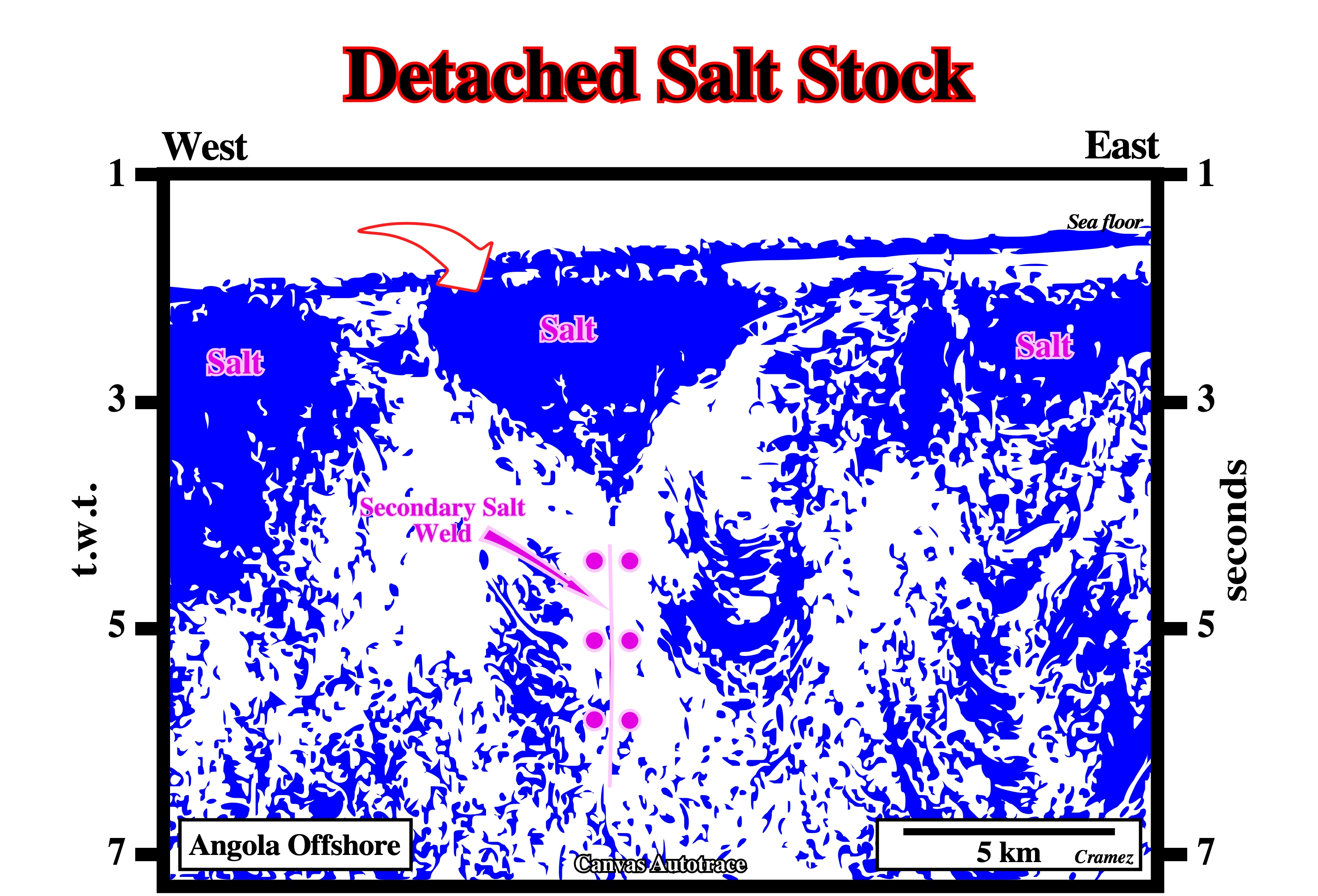
Detached salt structures are also known as drop structures ("gouttes" in French). They are separated from the mother salt layer by a vertical salt weld (secondary or tertiary salt weld), which can be predicted, and sometimes picked, using the geometry of the reflectors underlain the detached structure.
Deviatoric Stress
A deviatoric stress is a stress component in a system which consists of unequal principal stresses. There are three deviatoric stresses, obtained by subtracting the mean (or hydrostatic) stress (σ−) from each principal stress (i.e. σ1− σ−, σ2 − σ−, and σ3 − σ−). The hydrostatic pressure is simply the negative of hydrostatic stress. Deviatoric stresses control the degree of body distortion. Directed stresses acting in particular directions. This causes the alignment of minerals, giving rocks their foliation. Depending on the direction of the stresses, different structures and/or textures may develop.
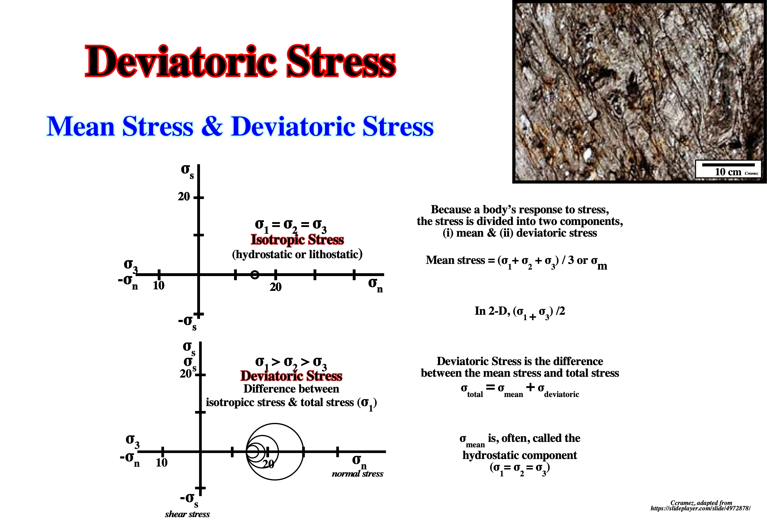
Stress is always simply , but some complexity does arise because the relative orientation of the force vector to the surface normal dictates the type of stress. When the force vector is normal to the surface, the stress is called normal stress . When the force vector is parallel to the surface, the stress is called shear stress. The foliation recognized in majority of the metamorphic rocks, as illustrated above, is induced by deviatoric stresses.
Devonian Salt Deposits (Zharkov, M. A., 1984)
Devonian salt-bearing deposits are known at present from a lot of geographic basins, as illustrated below.
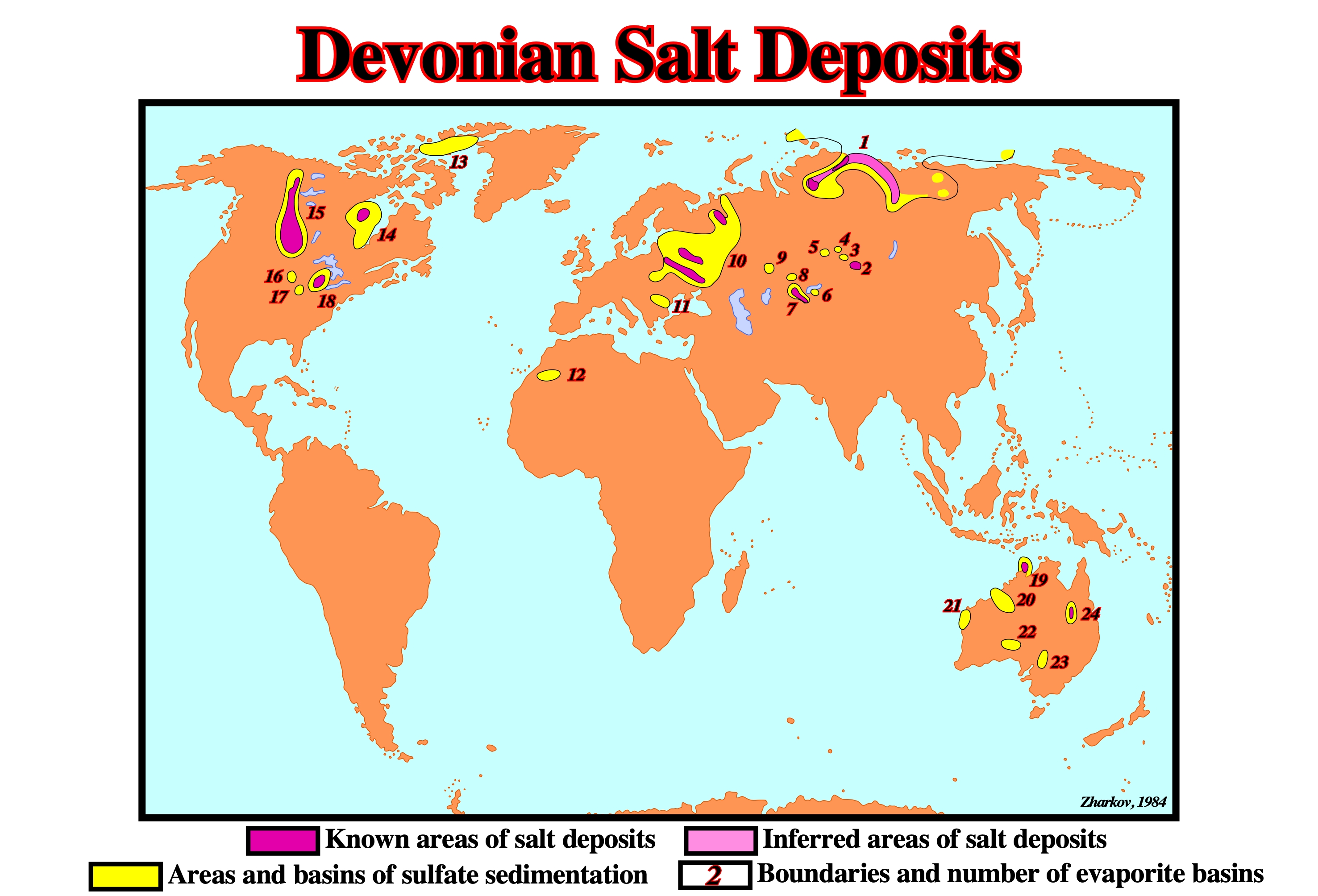
The Devonian evaporites illustrated on the above map come from the following geographic basins: (1) North Siberian ; (2) Tuva ; (3) Minusins ; (4) Chulym-Yenise ; (5) Ili ; (6) Chu-Sarysu ; (8) Teniz ; (9) Turgai ; (10) Morsovo and East European Upper Devonian ; (11) Moesian-Wallachian ; (12) Tondouf ; (13) Canadian Arctic Archipelago ; (14) Hudson ; (15) West Canadian ; (16) Central Iowa ; (17) Illinois ; (18) Michigan ; (19) Bonaparte Gulf ; (20) Canning ; (21) Carnavon ; (22) Arckaringa ; (23) Bancannia ; (24) Adavale.
Diapir
Mass of salt that has flowed in a ductile manner to discordantly pierce or intrude its overburden.
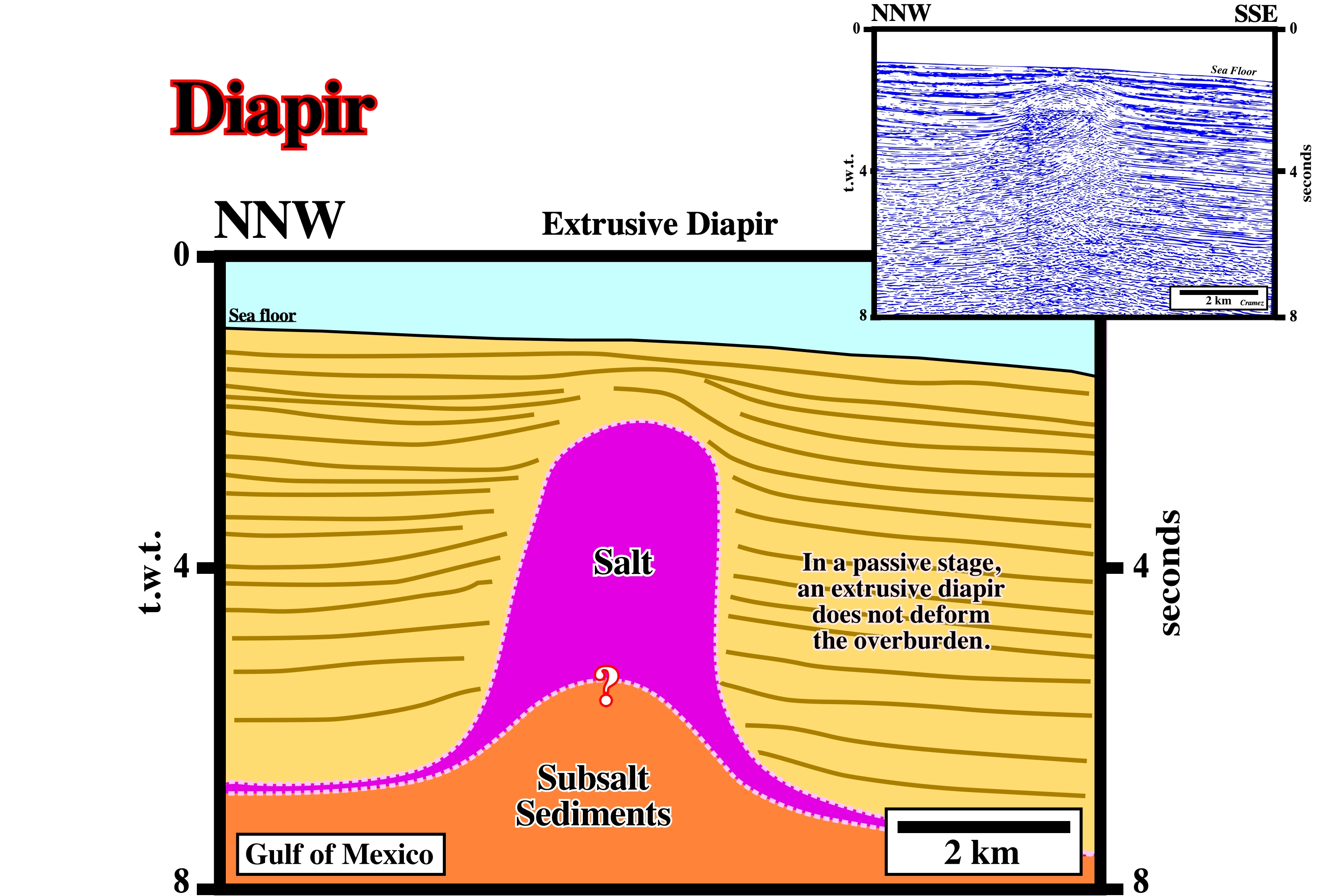
The preliminary tentative geological interpretation of this Canvas autotrace from a seismic line of the Gulf of Mexico, suggests an apparent diapirism. There is almost any deformation of the adjacent sediments of the overburden. Looks that the salt reach the surface quite soon and then, passively it moved upward as sedimentation of overburden progressed. On this tentative interpretation the diapir is, still, attached to the mother salt layer. In depth, the bottom of the diapir is roughly flat. However, such a depth is speculative. There is any marker associated with it and it is quite difficult to calculate the pull-up induced by the thickness of the diapir. Geological diapiric structures are, generally, considered to be driven upward, entirely, by buoyant forces resulting from the density contrast between a low-density layer and the heavier rocks above it. As the low-density material rises, there is a complementary sinking of the overlying-higher-density material. Shale diapirs form where folding of unconsolidated sediments has taken place or where rapid sedimentation and compaction have generated high fluid pressures in unlithified shales and caused them to move upward. They form ‘mud volcanoes’ where they reach the surface. Fabric and strain patterns of diapirs have been determined experimentally and numerically. There are internal structures formed by flow in the intruding mass and external structures expressing the deformation of the country rock by the piercing diapir. The pattern of these secondary structures reflects the diapiric mechanism. (http://www.files.ethz.ch/structuralgeology/JPB/files/English/ 12diapirs.pdf)
Diapiric Fold (Ruig, M. J., 1995)
The expression used by several authors, in Eastern Prebetic Foldbelt, in reference to folds in the overburden that are supposedly cored by Triassic evaporites. These folds are thought to have been forced by the active diapiric rise of evaporites. However, when they formed, no clear density inversion existed between the Triassic evaporites and their carbonate cover, which precludes uplift of large blocks of the overburden. It seems these folds were formed by buckling, under lateral compression, rather than by vertical diapiric motion. Synomym of Diapiric Uplift.
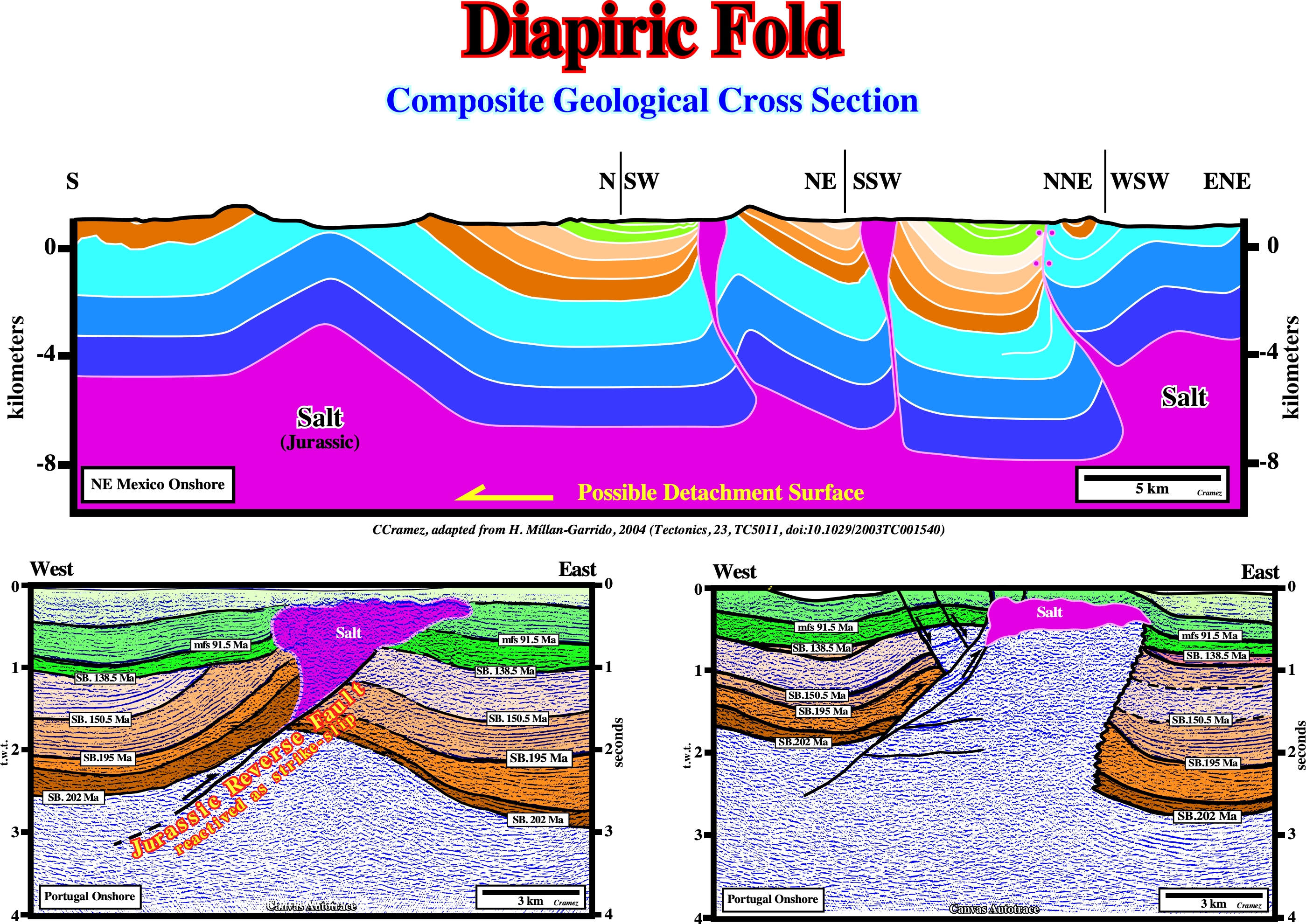
On the geological cross-section, as on the tentative geological interpretation of the Canvas autotraces (Portugal onshore seismic lines), the salt structures can be considered as diapiric folds since they are excellent examples of tectonically controlled diapirism. In the geological cross section the sediments were deformed by a thin-skinned tectonics forming typical folds developed in multilayer that underwent a shortening more or less parallel to the bedding. Later the folds were penetrated by Jurassic salt diapirs, responsible of the growth observed in Late Cretaceous-Tertiary strata. On the Canvas autotraces, the salt emplacement is associated with the reactivation in strike-slip of an reverse fault, which is, probably, the reactivation of an old normal fault controlling the salt deposition.
Diapiric Uplift
See diapiric fold.
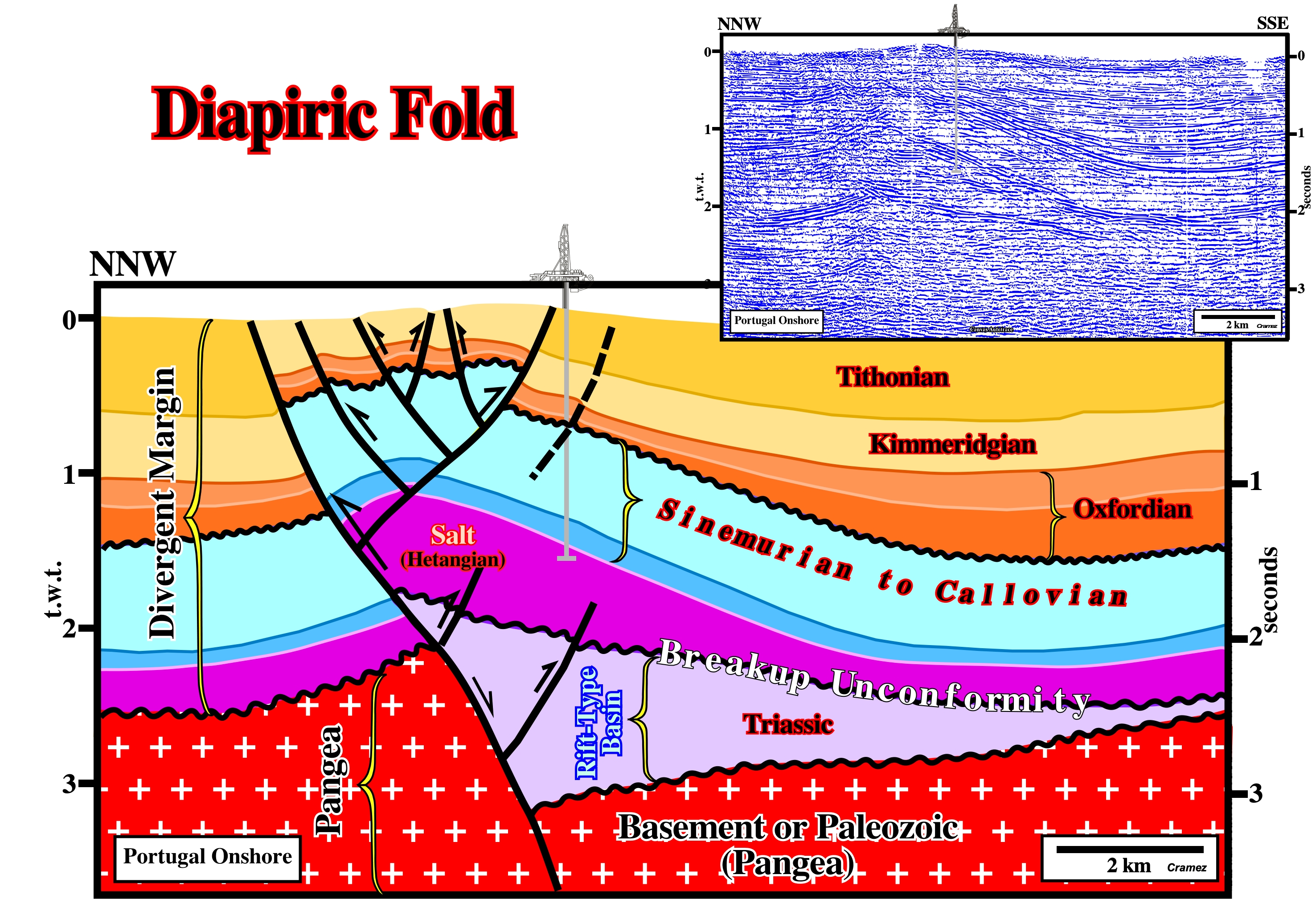
On this tentative geological interpretation of a Canvas autotrace of a seismic line of the Lusitanian geographic basin (Portugal onshore), the salt structure can be considered as a diapiric uplift, since the salt structure is tectonically controlled. A tectonic inversion is quite evident. The old normal fault bordering the Triassic rift-type basin was, significantly, reactivated with a reverse movement. The null point is located in lower section of the fault plane. The inversion started in Lower Oxfordian, but the chiefly paroxysm seems to have been in Late Tertiary. The drilled well, as the majority of wells drilled in this area, was drilled in a high point of a structural traps, likely, posterior to the migration of the, eventually, generated hydrocarbons.
Diapirism
General term expressing different processes of piercing or rupturing of domed or uplifted rocks by mobile core material.
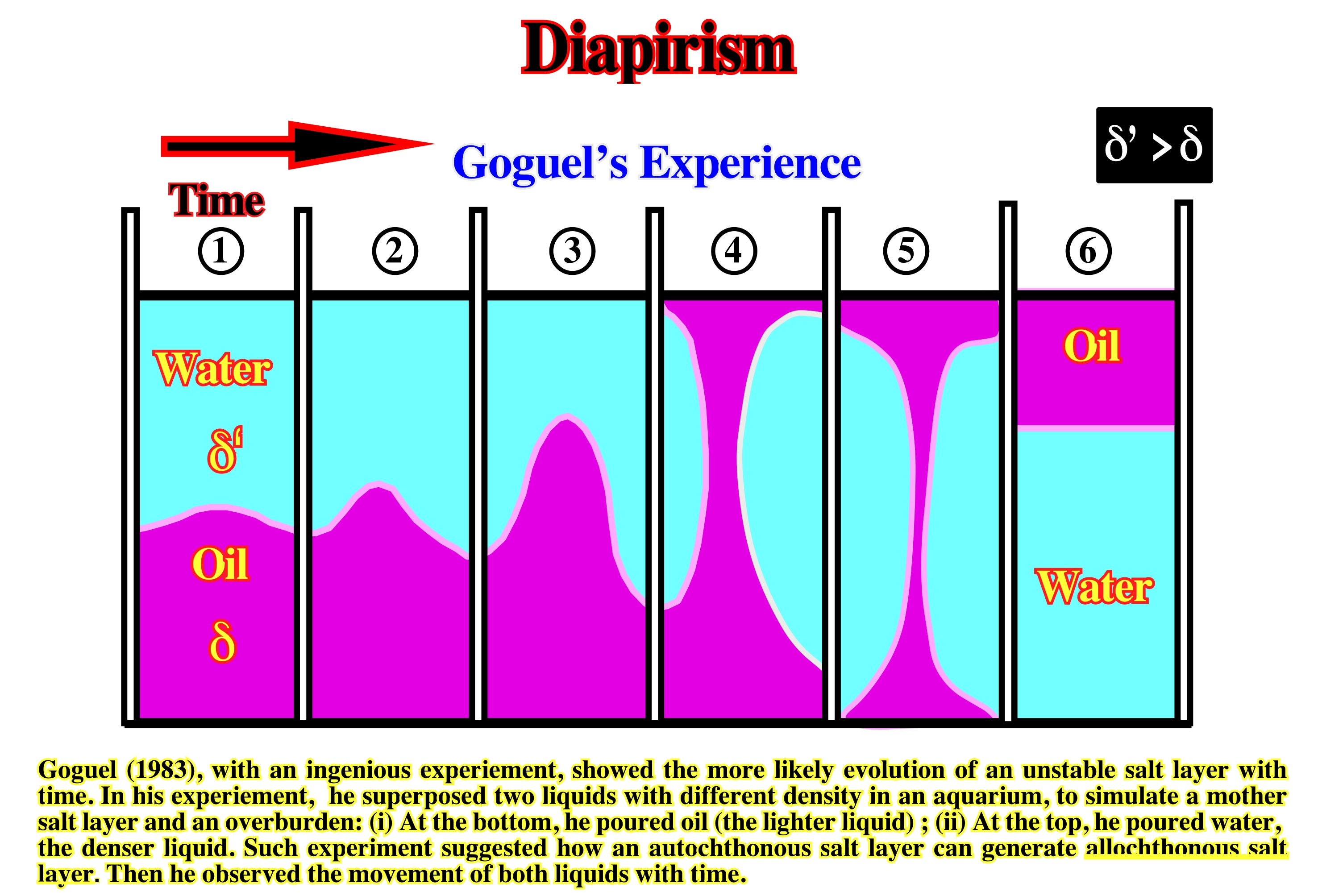
A lighter fluid under a denser one is an unstable situation. Thereby, with time, the lighter fluid will become to surface, while the denser goes to the bottom. During such an inversion, several steps or stages can be considered: (1) Small Positive Anomaly, at the oil-water interface small an anomaly is formed (in a large aquarium equidistant anomalies develop) ; (2) Mound Stage, the anomaly grow-up forming a mound characterized relatively flat flanks ; (3) Dome Stage, the mound grows and become a dome (their flanks reach a quite high dip, near the vertical) ; (4) Post-Dome Stage, since a dome arrives at surface, the oil starts to flow laterally, creating post-dome structures (in the case of several domes some of these structures become disconnected from the mother oil layer) ; (5) Canopy Stage at surface, the oil flowing in opposite direction creates canopy structure similar to those created by ascendant convection currents ) ; (6 ) Stable Stage, finally, all oil will be transferred at surface, reaching an equilibrium state.
Differential Loading
Creation of lateral pressure gradients on salt caused by surface slope or lateral variations in thickness, density, or strength of the overburden. Such variations may be sedimentary or structural. Unlike the buoyancy mechanism, differential loading requires no density inversion or burial of salt below the level of neutral buoyancy to operate; it is thus an effective initiator of halokinesis and is especially effective near surface.
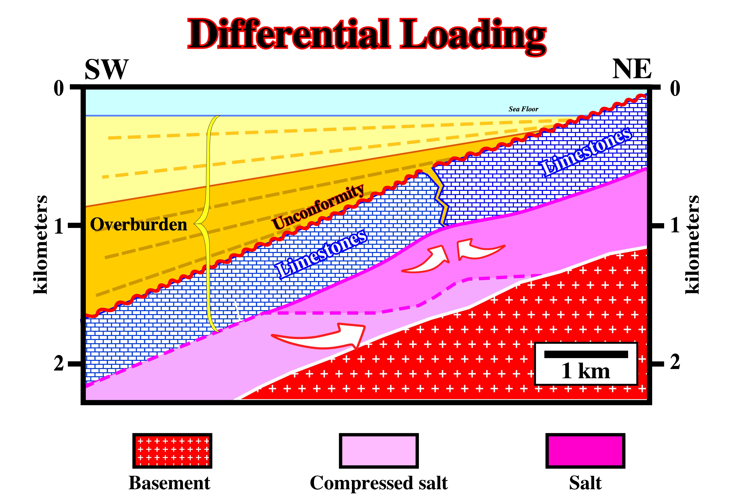
Whenever a salt interval is overlain by overburden whose average density exceeds that of the salt, there is a mechanically unstable situation. Different geological situations can be considered: (i) Isopachous and Homogeneous Overburden ; (ii) Variable Overburden Thickness ; (iii) Tectonic Tilting. Physically speaking, a tectonic tilting of the salt, as illustrated above, is equivalent to a thickness variation of the pre-tilting overburden. The progressive seaward thickening of the overburden, mainly due to thickening of the post-unconformity sediments, creates a differential pressure on the salt layer that, when big enough to overcome the friction strength, obliges the salt to flow. When the top of the salt layer has a tectonic dip, the salt moves in a direction, which depends on the average density of the overburden: a) If the average density of the overburden is lesser than that of the salt, the salt moves down-dip ; b) If the average density of the overburden is greater than the density of the salt, the salt moves up-dip. For an overburden thicker than 1,000/1,500 m, the average density is higher than 2.15, thereby the salt tends to flow up-dip. Nevertheless, as, generally, salt movements are initiated under much less thick overburden, the salts flows down-dip.
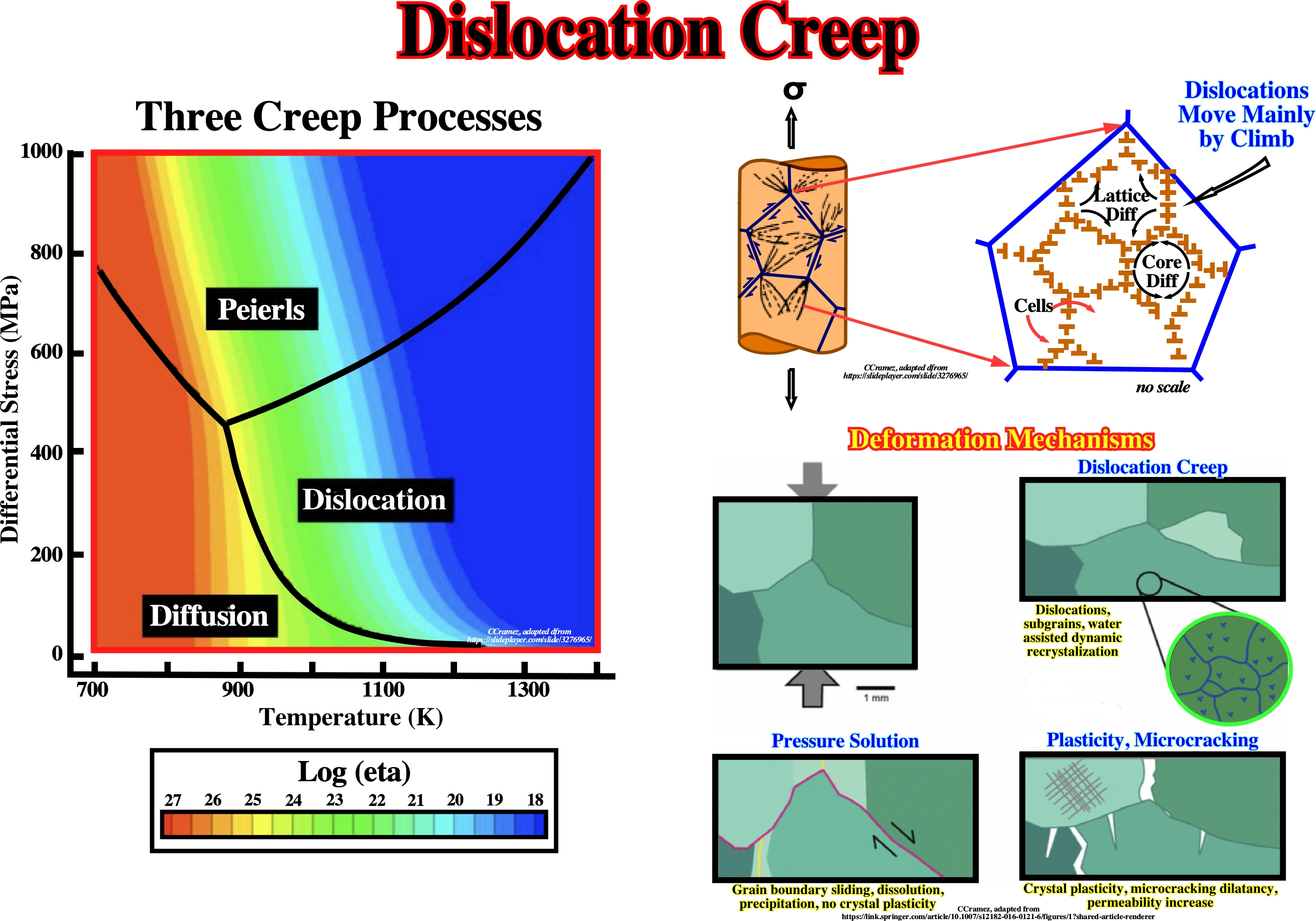
Dislocation Creep
An intracrystalline plastic flow involving a combination of glide and climb of dislocations through the crystal lattice to change grain shape. At low temperatures, grain boundaries and inclusions can obstruct gliding, resulting in dislocation tangles and work hardening. At higher temperatures, recovery takes place by cross-slip and climb past obstacles. This annihilates dislocation tangles or orders them into dislocation walls by polygonization. Dislocation creep is dominant at high deviatoric stresses and high strain rates.
Generally, rocks respond to stress in one of two ways: a) Breaking or b) Bending. When a rock breaks, the deformation is said brittle, i.e., it exhibits a brittle behavior (sudden and very rapid cracking under stress where the material exhibited little or no evidence of ductility or plastic degradation before the fracture occurs). When a rock bends or flow, the deformation is called ductile. In the ductile deformation there are three mechanisms, function of the differential stress (MPa) and temperature K : (i) Dislocation creep ; (ii) Diffusion creep and (iii) Peierls creep. Dislocation creep involves processes internal to grains and crystal of rocks, in fact, in any crystalline lattice there are always single atoms, i.e., point defects or rows of atoms , i.e., line defects or dislocations missing. These defects can migrate or diffuse within the crystalline lattice. The motion of these defects allows a crystalline lattice to strain or change shape without brittle fracture. Diffusion creep involves the transport of material from one site to another within a rock body (the material transfer me be intra crystalline , inter-crystalline or both). Peierls creep involves mixed glide and climb. This mechanism has a finite field stress (Peierls stress) at absolute zero temperatures conditions. The Peierls stress is the force needed to move a dislocation within a plane of atoms in the unit cell.
Dissolution (Salt)
Salt, as other rocks, can be dissolve whether, at bottom of the sea, by seawater or, in depth, by an aquifer. Salt dissolution can create complex structures in the overburden that are often difficult to interpret as illustrated below.

In North Sea, particular structures, as the one illustrated above, can be recognized on seismic lines. Such structures cannot be explained by the conventional tectonic regimes. Salt dissolution is, often, the more likely explanation. These structures were explained by Shell's geologists invoking a complete dissolution of an autochthonous salt layer by the sand 1 (aquifer).
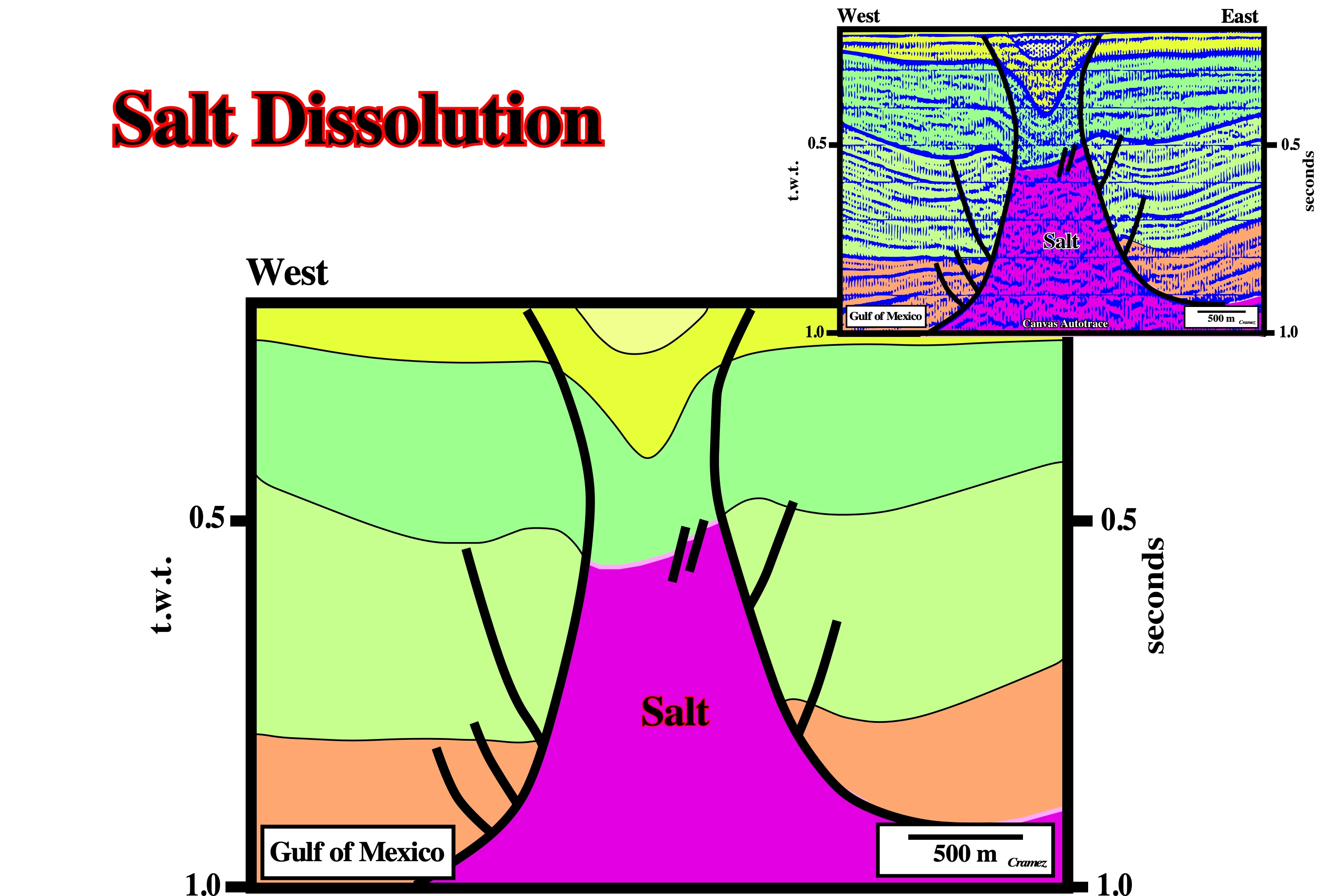
A salt-dissolution depression, on the top of the salt dome, is quite evident. The salt dome was squeezed. The synform and antiform structures are, easily, explained by the volume problem induced by the salt dissolution rather than a shortening created by a local compressional tectonic regime. Just above of the dome, the topography of the sea floor (not visible on this Canvas autotrace) has a subcircular trough morphology, similar to that of the Grand Saline dome, in onshore Texas.
Dolomite
A common rock-forming rhombohedral mineral: CaMg(CO3)2. Part of the magnesium may be replaced by ferrous iron and less frequently by manganese. Dolomite is white, colorless, or tinged yellow, brown, pink, or gray. It had perfect rhombohedral cleavage and a pearly to vitreous luster, effervesces feebly in cold dilute hydrochloric acid, and forms curved, saddlelike crystals.
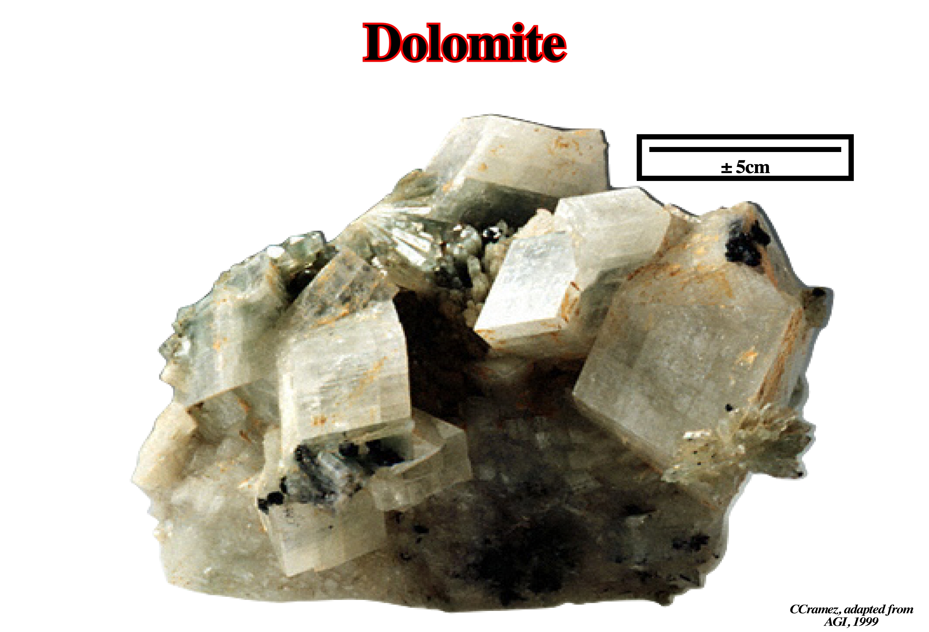
Dolomite is found in extensive beds as dolomite rocks. It is a common vein mineral, and is found in serpentinite and other magnesian rocks. Dolomitization is a process by which a limestone is changed in dolomite (sedimentary organogenetic rock constituted by dolomite, calcite, with traces of clay, quartz, pyrite and marcassite). When a limestone is in contacted with a water rich in magnesium, the dolomite, calcium carbonate mineral and magnesium, CaMg (CO3 )2, replaces calcite (calcium carbonate, CaCO3) in the rock, volume by volume. Dolomitization implies large-scale recrystallization. The dolomite (mineral) grains, which often show very distinct crystallographic faces, have, more or less, an uniform size that is smaller than the grains of calcite. When the recrystallization is not complete, the dolomite crystals are disseminated in a calcite matrix. Certain limestone rocks exhibit patches of dolomite (different colour), which geoscientists interpret as the result of local contamination by waters rich in magnesium. Dolomite stains which are, totally, independent of the stratification may also be the result of a simple separation from a crystalline mixture of calcium and magnesium carbonates as well as magnesium carbonate, i.e., a local precipitation of dolomite CaMg (CO3 )2. Dolomitization is very common in supra-tidal sabkhas where magnesium ions resulting from evaporation of water replace calcium ions in calcite and form dolomite. As the volume of dolomite is lower than that of calcite a dolomitization implies a porosity increasing of, more or less, 13%.
Dome
See: Diapir
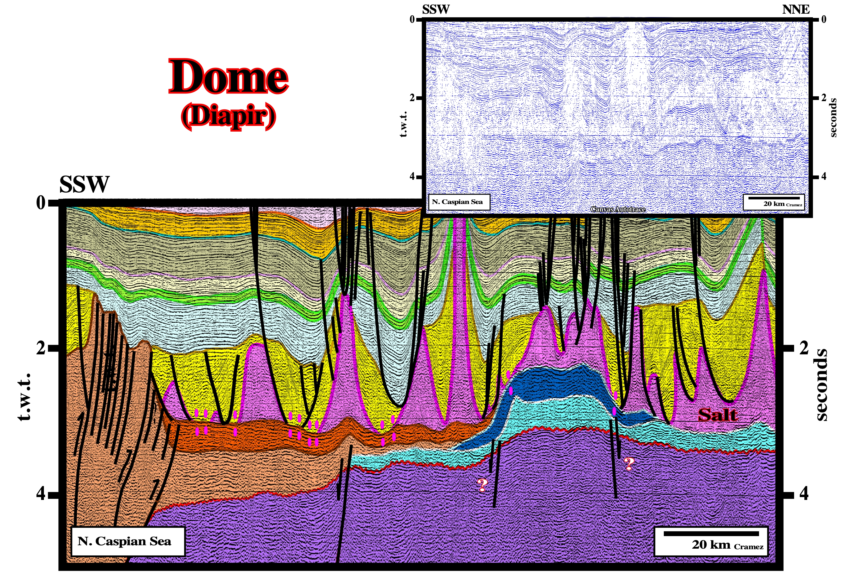
On this tentative geologic interpretation of a Canvas autotrace of a regional North Caspian Sea seismic line, nearby the Kasaghan oil discovery (dark blue), salt domes and salt ridges striking, perpendicularly, to the thrust-faults and cylindrical-folds of the fold-belt (in the left end of the line) are present. The differentiation between these two types of salt structures is quite difficult on a single seismic line. However, on time slices or in a map, salt domes exhibit a circular morphology, while salt ridges have a more or less rectilinear morphology. Salt domes are, often associated with halokinesis, while salt ridges are, often, tectonically controlled.
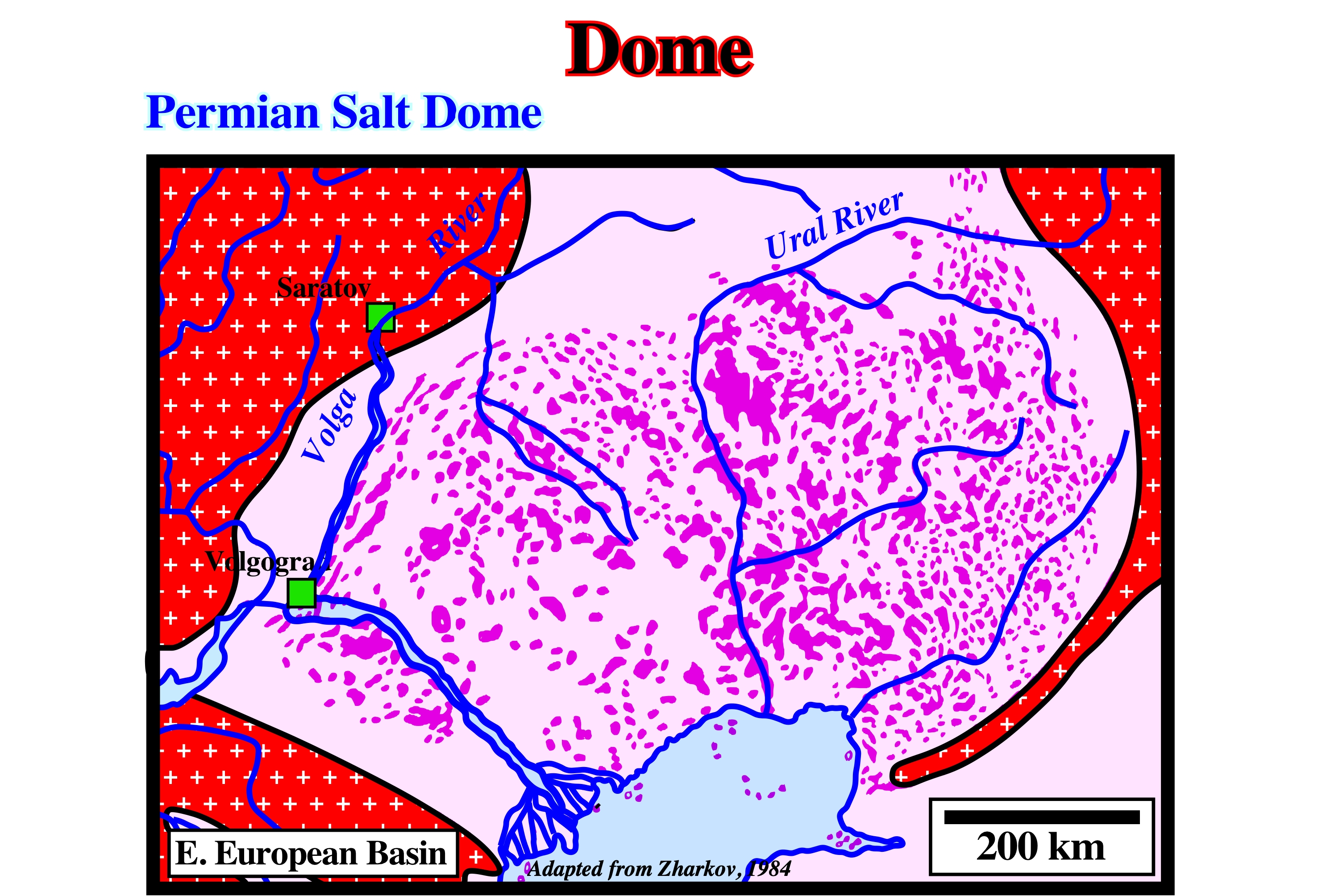
The mapping of the Permian salt of the Eastern European Salt geographic basin suggests that the Rayleigh-Taylor instability was a main mechanism controlling the spatial distribution of the salt structures. Indeed, on this map, besides on the western most area (near the Volga River), it is difficult to recognize a particular lineation pattern on the distribution of the salt structures. In other words salt dome structures look preponderant.
Dome Stage
A salt structure, generally, disconnected from the mother salt layer with thick overburden depocenters are developed around it. Depocenters developed during the mound stage are, generally, located outward of those associated with the dome stage: depocenters migrate toward the flanks of the dome.
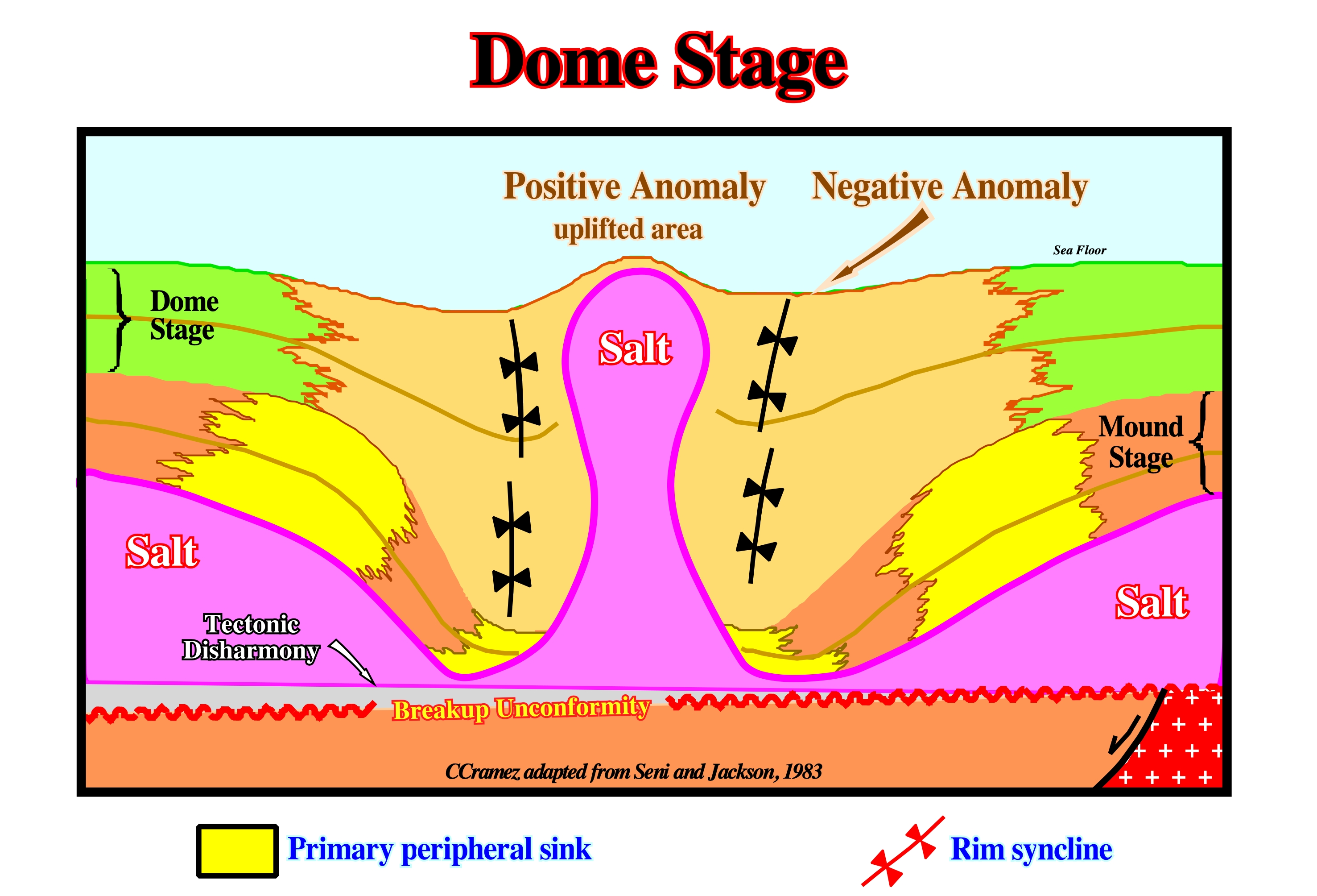
The continuation of the salt flowage from the flanks toward the central part of the salt mound, as the thickness of the overburden increases (depocenters), creates an uplift the apex of the mound forming a dome structure or diapir. The differential subsidence induced by the salt movements creates depocenters in the overburden, in which the central parts are displaced toward the dome. The apex of the dome continues to rise until the salt of the dome will be completely isolated from the mother salt layer. In such a geological situation, the flanks of the mature dome (are almost vertical. However, due to the geostatic inversion point, such a subvertical geometry is mechanically unstable. With time the unstable dome geometry changes to a stable post-dome geometry. Notice the migration of the depocenters towards the flanks of the salt dome, as well as the uplifted area just above the top of the dome.
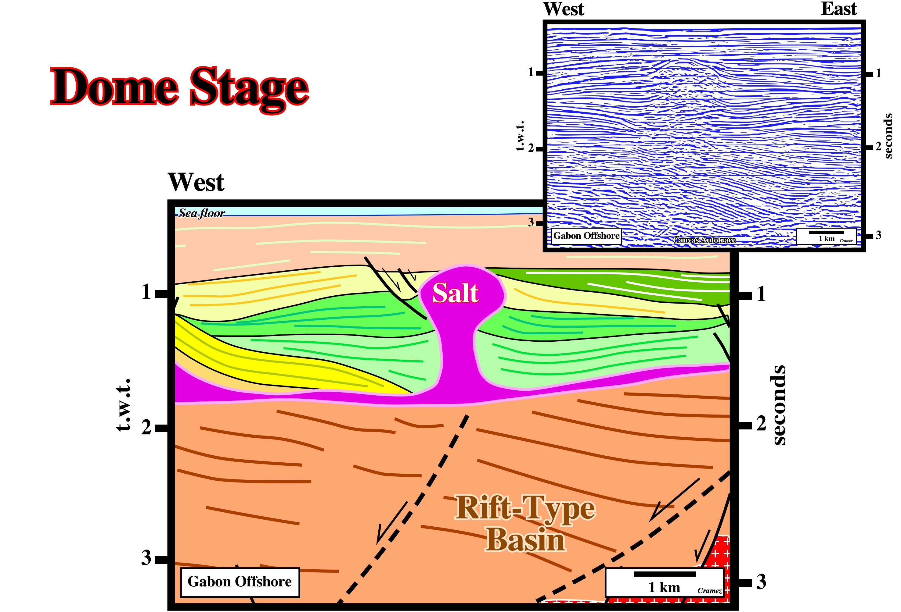
On this tentative interpretation of a Canvas autotrace of Gabon offshore seismic line, as illustrated in the previous sketch, the depocenters migrate toward the flanks of the dome, which is not disconnected of the mother salt layer.
Dominant Wavelength (δc)
The observed periodic spacing of an instability. It may differ from the characteristic wavelength if the interface is, initially, deformed or if Rayleigh-Taylor instability is influenced by other effects, such as differential loading, regional strain, thermal convention, or faulting. Synonym with Characteristic Wavelength (δc).
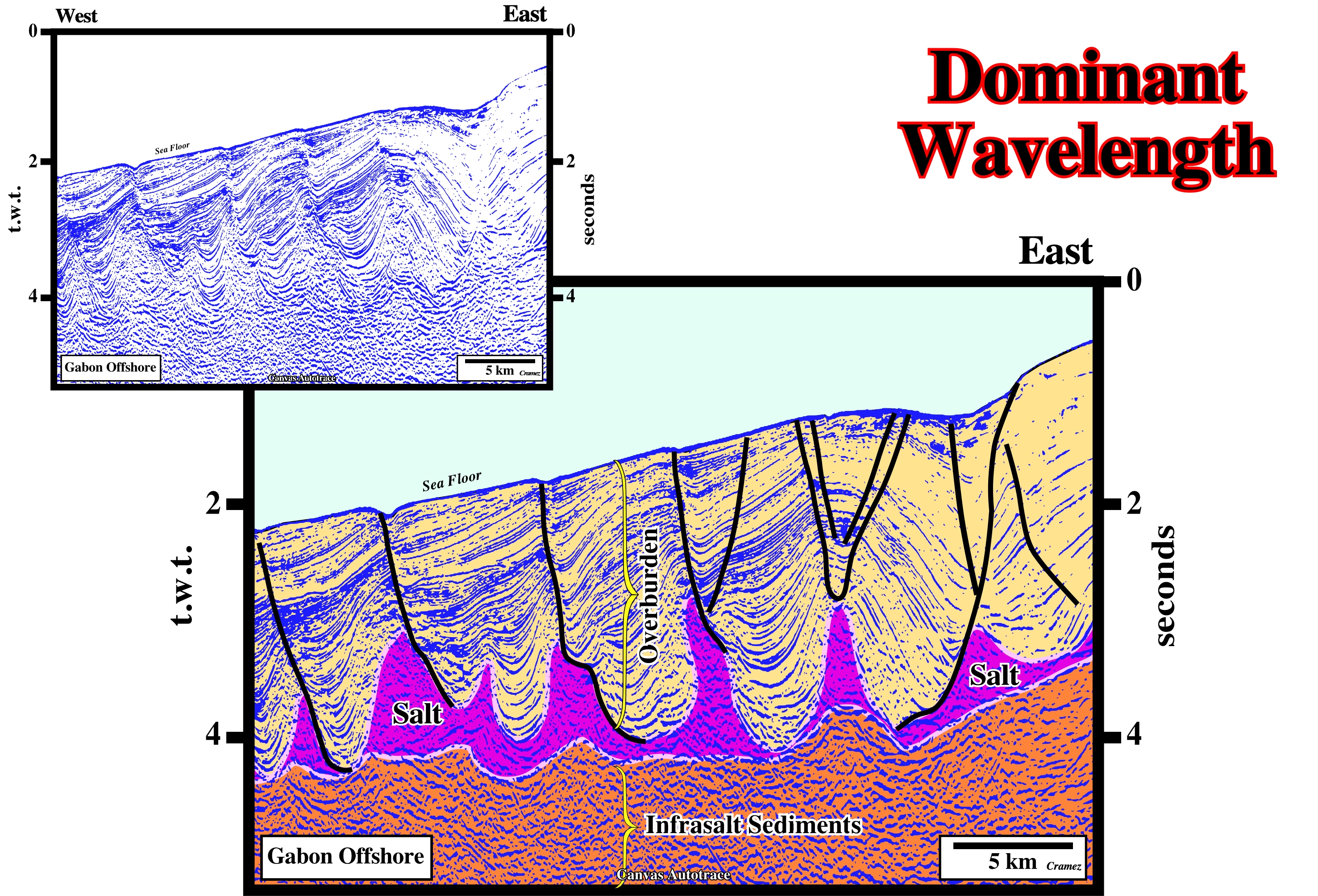
The landward dipping faults, which are well marked by the sea floor morphology, suggest a local up-dip movement of the salt layer with formation of salt domes, periodically, spacing. Such a particular upward fault geometry occur, mainly, when the lower section of the overburden is denser than the salt. A limestone facies of the lower overburden is likely. On the other hand, the divergent internal configuration of the lower part of the overburden implies that it s deposition is coeval with the salt flowage.
Downbuilding
Syndepositional diapir growth. Synonime of passive piercement.The structure increases relief by growing downward relative to the sedimentary surface. Its base subsides together with surrounding strata as the basin fills with sediment, while its crest remains at or near the surface.
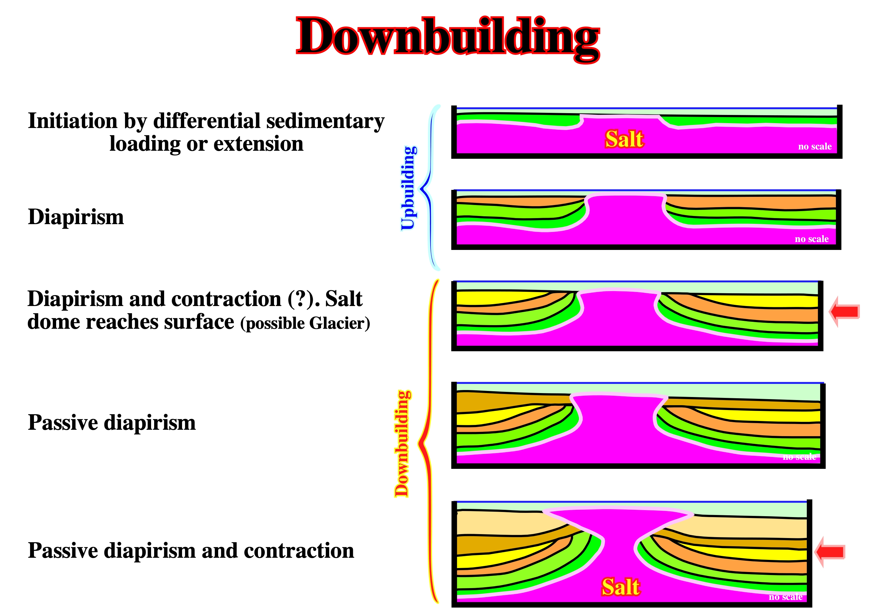
This downbuilding tectonic evolution was proposed as a likely explanation of the Green Knoll structure, in Gulf of Mexico, which is illustrated on the Canvas autotrace of a Gulf of Mexico seismic line below.
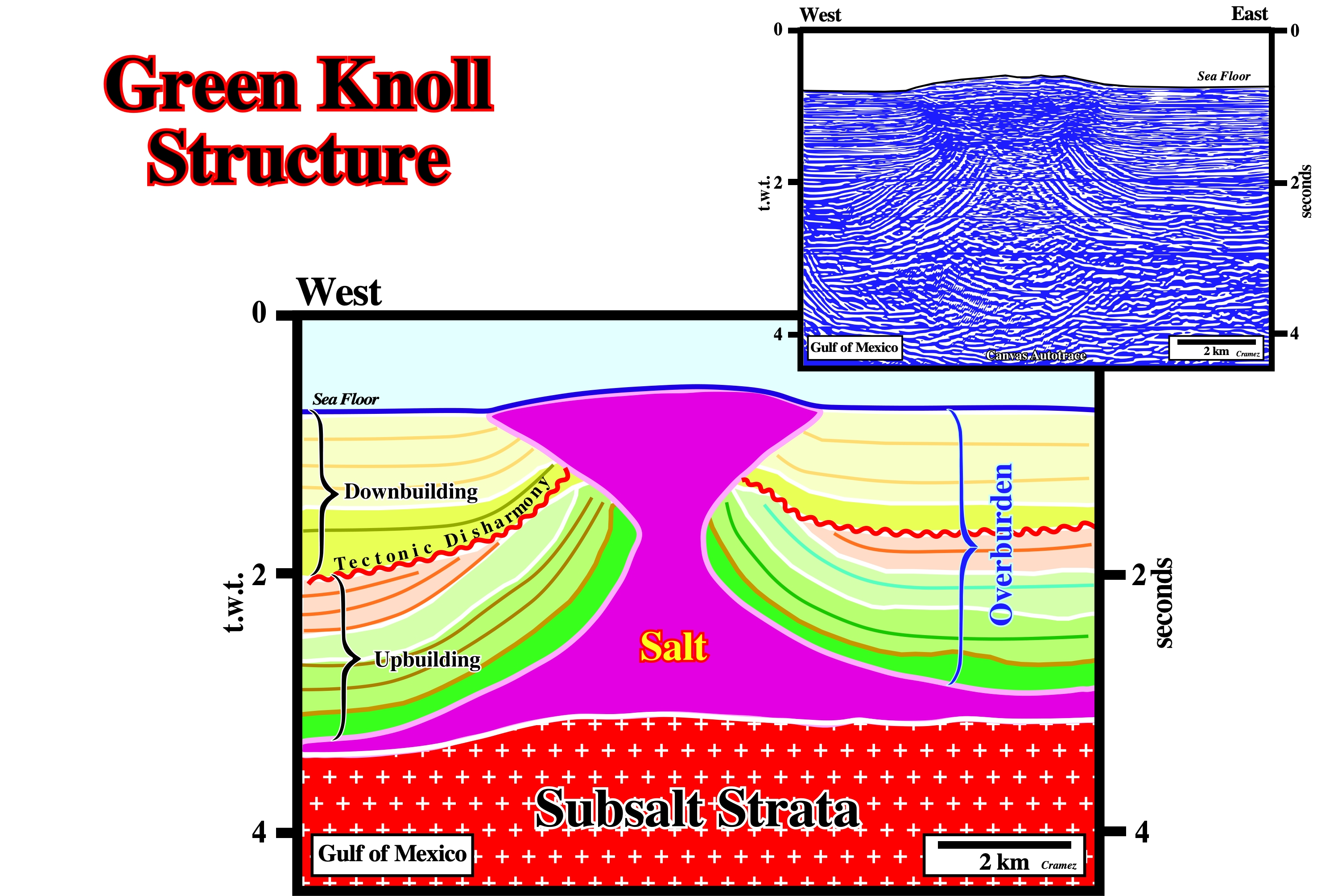
This structure (Green Knoll) is explained by certain geoscientists as a consequence of a downbuilding evolution associated with passive diapir and contraction. Its hydrocarbon potential was tested recently, but the result, as suggested by the proposed evolution (see previous figure), were more than disappointing.
Downlap
Basal geometrical relationship in which initially inclined strata terminate down-dip against an initially horizontal or less inclined surface.
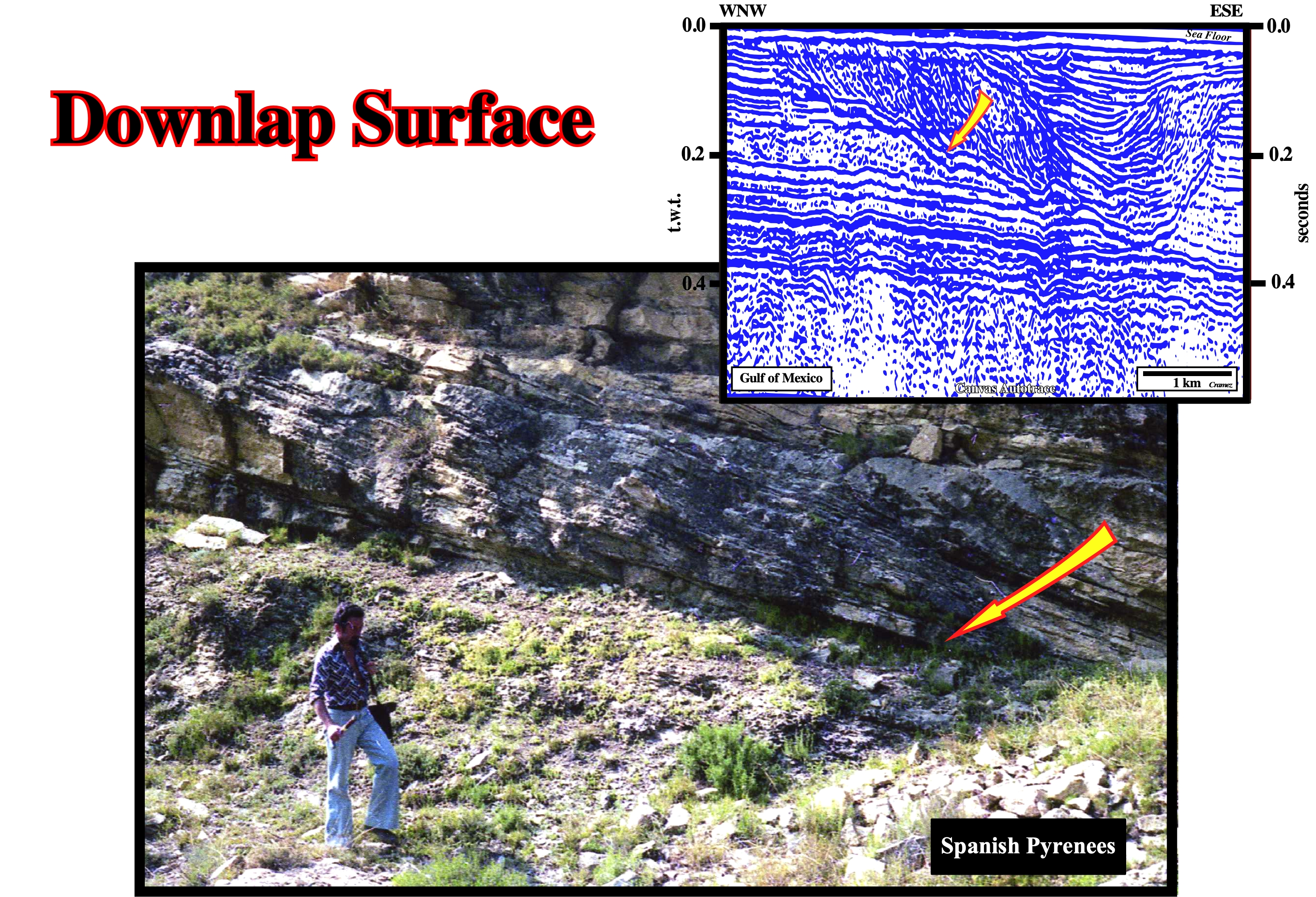
Downlap surfaces, as the one illustrated above (bottom of a point bar), are at the base of progradational or regressive interval. Seismic downlap is a downlap surface interpreted from a Canvas autotrace or a seismic section. It is a relation in which seismic reflection interpreted as, initially, inclined strata terminate down-dip against a reflection discontinuity interpreted as an, initially, inclined or horizontal unconformity. Apparent downlap on seismic section may occur where reflections are representing units of inclined or tangential strata terminate down-dip, but the strata themselves, actually, flatten and continue as units which are so thin that they fall below the resolution of the seismic tool.
Downward Fault Compartment
Synonym of Hangingwall.

The sediments are lengthened by normal faults. The lengthening of the sediments is evident on this tentative geological interpretation of a Canvas autotrace of the Aegean Sea seismic line. The tectonic regime is characterized by σ1 vertical. The antiform morphology of the sea bottom is quite significant. The majority of the normal-faults die on the tectonic disharmony associated with the salt layer (top of the salt). The sediments above and below the tectonic disharmony show different deformations. Above it, the substratum, i.e., the salt and overburden have been strongly extended (the extension still is going on). Below the tectonic disharmony, the infrasalt strata are just slightly deformed. The cartography of the salt structures, which are bordered by normal-faults, indicates they have a more or less rectilinear geometry. Thereby, the salt structures can be considered as salt ridges striking parallel to σ2.
Downward Salt Bulb
Decoupling above and below evaporites. In certain salt basins and particularly in Iran, the Miocene salt decoupled upper cover from lower cover in such way that salt flow into the overlying anticline and underling synclines. This segregation formed salt bulbs (looking upward and downward) laterally separated by much thinner salt.
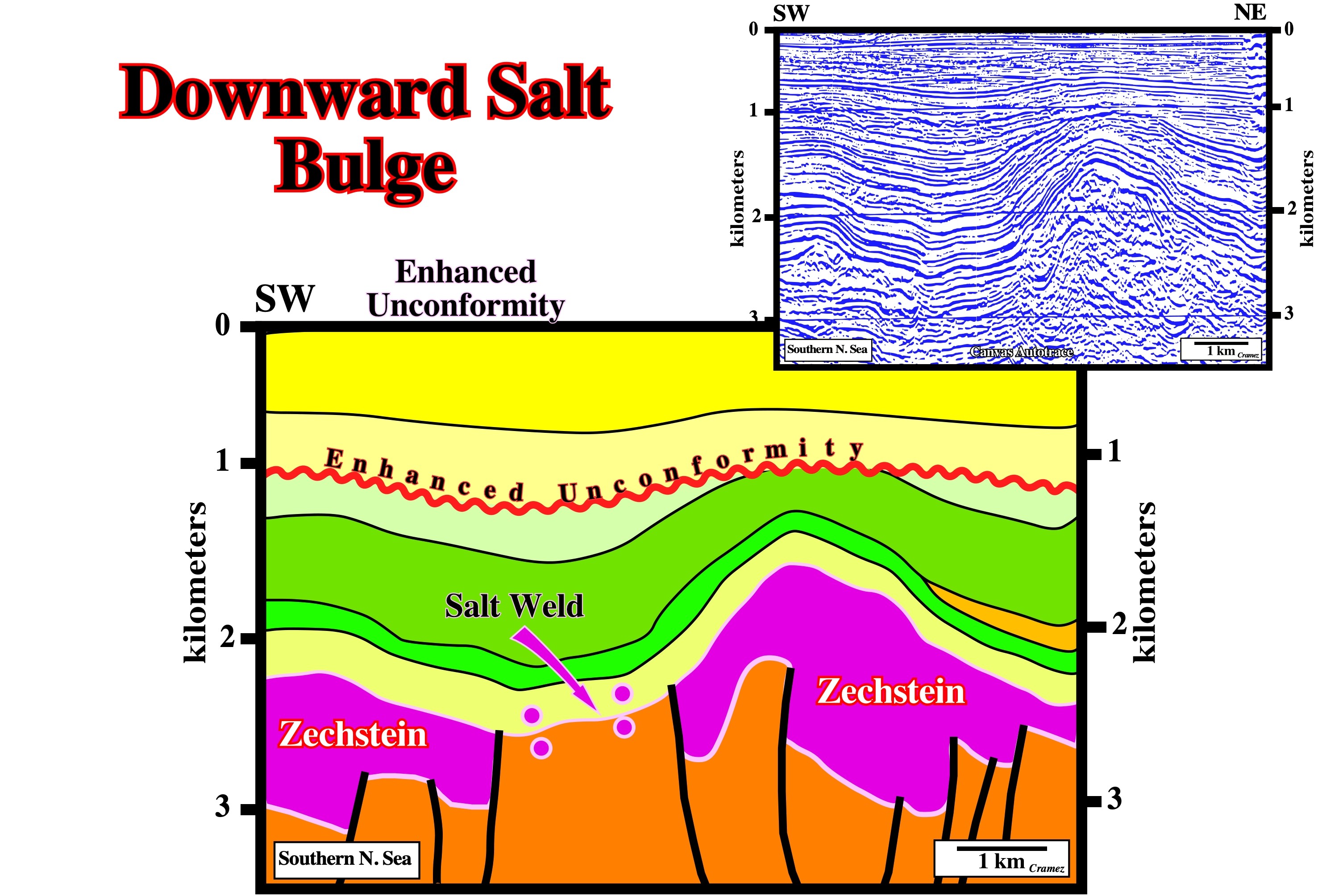
This tentative geological interpretation of a Canvas autotrace of a Southern North Sea seismic line can be used as an example of downward salt movement assuming : (i) There is no significant extension before the salt deposition ; (ii) The salt was deposited in a, more or less, horizontal and continuous stratigraphic layer ; (iii) Overlying the salt, isopachous sedimentary intervals were deposited (prekinematic layers) ; (iv) A regional extension took place and reactivated, as normal faults, the pre-existent faults or fracture zones of the infrasalt strata ; (v) The salt flowed, laterally, and downward filling the space created by lengthening ; (vi) Such a salt flowage induced in the overburden (above the prekinematic layers) a depocenter as well as a tectonic disharmony and a salt weld ; (vii) A regional compressional tectonic regime took place and thereof the cover was shortened ; (viii) The compression could locally reactivate the salt layer initiating a halokinetic phase.
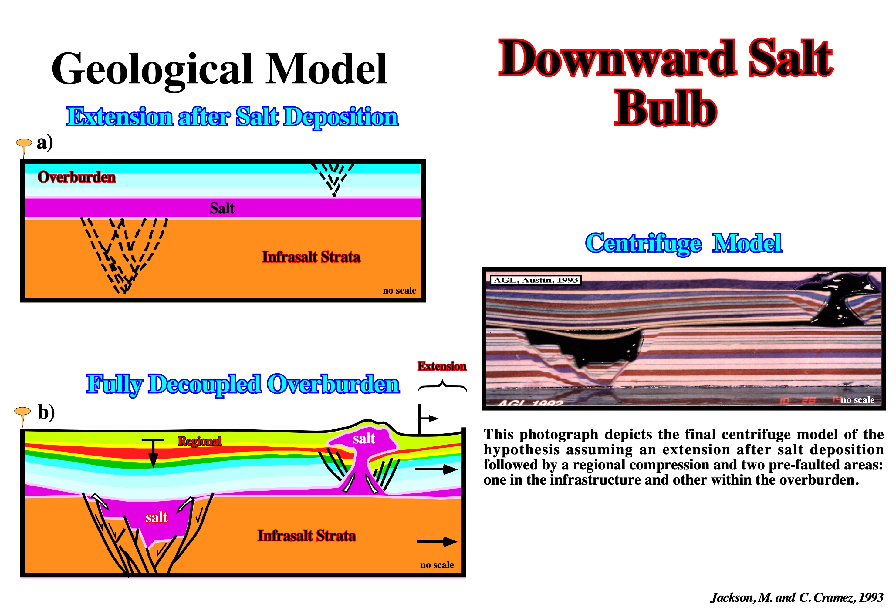
A post-salt extension fits quite well the observed data. The undulations of the overburden area associated with a late compression. The depocenter overlying the isopachous layers dates the lateral and downward flowage of the salt, as well as it divides the overburden into prekinematic and postkinematic and the age of the salt weld. The geometry of the grabens is similar to the one recognized on seismic data. The salt diapir developed on the pre-faulted area of the overburden fits also the salt structures found on seismic data (before the late shortening, i.e. before the fault reactivation).
Drag Zone
Zone of bending strata on either side of a fault or salt flanks. Drag may occur because a fault surface or salt flanks are curved or as a manifestation of the resistance to slip.
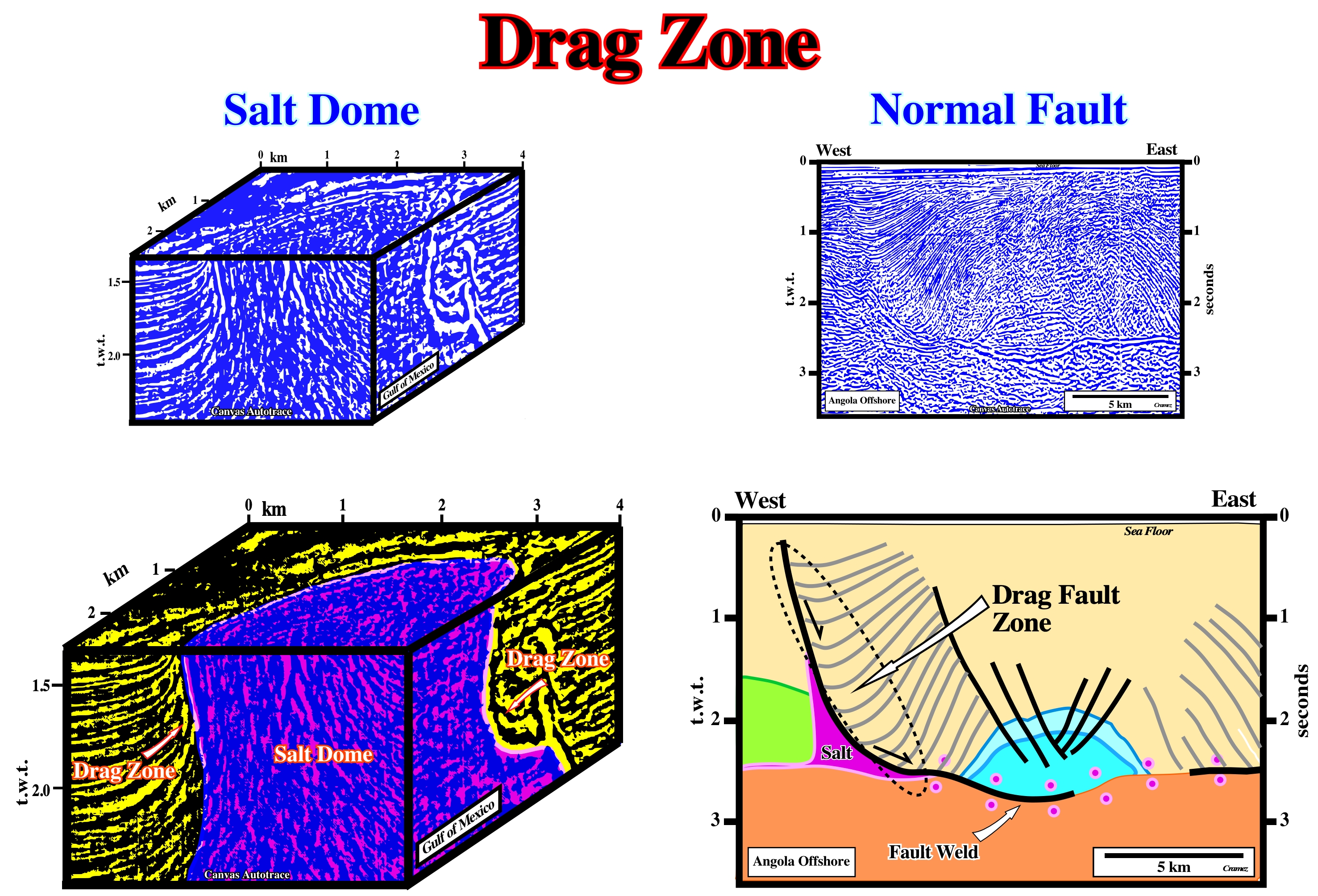
The limits of the salt diapir are marked by strong deformed reflectors which form a drag zone. On the time slice, the reflections are concordant. The original geometric relationships between the seismic markers were deformed by salt flowage. Around the diapir, the deformation (drag zone) of the overburden reflectors is not homogeneous. The chaotic seismic reflectors within the salt emphasize the flowage of the salt. The antiform structure is a typical extensional structure created by halokinesis, in which the lateral depocenters are synkinematic intervals deposited in association with a compensatory subsidence created by salt flowage. The limits of the depocenters correspond to drag zone developed in the hangingwalls of the growth faults bordering the turtle back structure. The core of this structure,which is mainly prekinematic, was inverted by halokinesis. The normal faults with opposite vergence located near the apex of the turtle back antiform extend to the upper overburden intervals.
Drop Structure
Synonym of Detached salt stock.
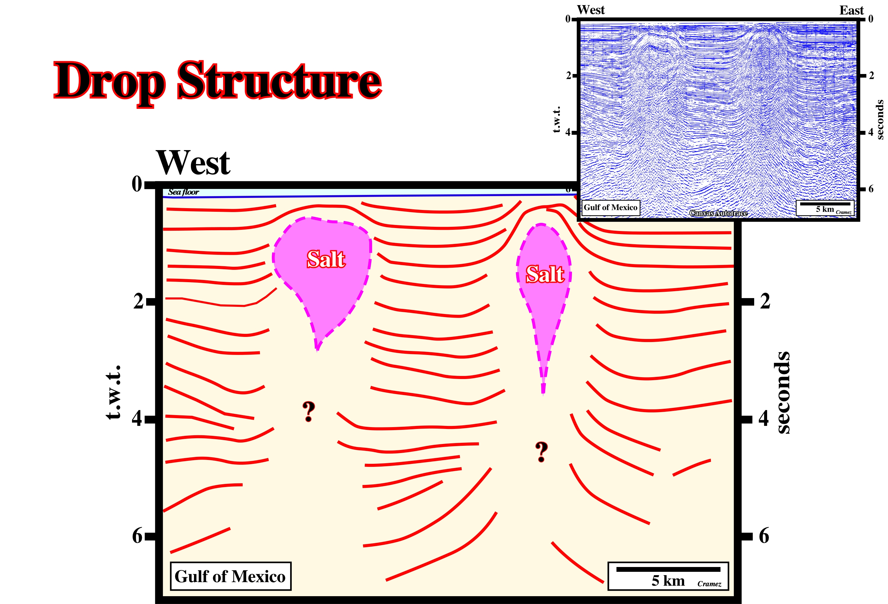
On this preliminary tentative geological interpretation of a Canvas autotrace of a GOM seismic line, it is quite difficult to see whether the drop structures are associated with an allochthonous salt nappe or to a deeper autochthonous salt layer. Indeed, two obvious tectonic disharmonies are recognized. One at 4.2 seconds and another at 6.0 seconds (t.w.t.). Certain geoscientists attach the eastern structure to the mother salt layer (autochthonous salt), while the western structure is attached to an allochthonous salt layer, which is just underlined by a vertical salt weld.
Dyke
A tabular igneous intrusion that cuts across the bedding or foliation of the country rocks. In salt tectonics few geologists use the term salt dyke as synonym of salt sill.
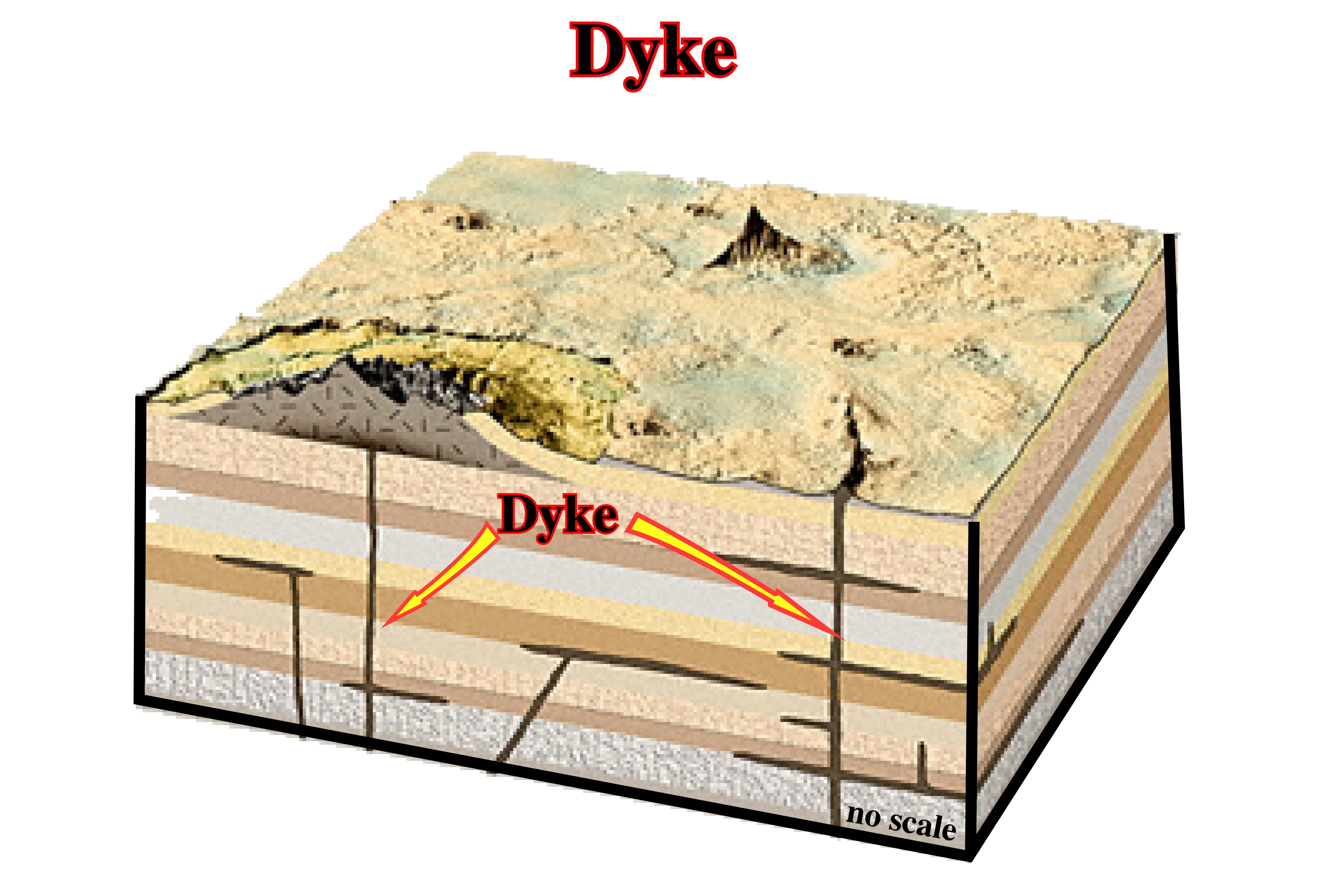
Dyke sets, i.e., groups of linear or parallel dykes are often good hydrocarbon reservoirs, as it is the case in certain oil and gas fields in Argentine. However taking into account the dimensions of the dykes, generally , they cannot bre recognized on the seismic lines.
Dynamic Bulge
Bulge caused by pressure of flowing fluid against its overburden, as the viscous flow (analogous to a fountain) of salt upward from a diapir stem. Such bulges can extend above the level of neutral buoyancy, the most striking examples being the mountainous extrusive salt domes of southern Iran. Dynamic bulges can lift strata above the regional surface. This deformation is recorded by onlapping strata and erosional truncations, which may themselves be deformed later. A dynamic bulge is likely to subside after the underlying stem pinches off or the source layer is exhausted. The record of a decaying bulge is preserved as structural inversion in any synkinematic overburden.
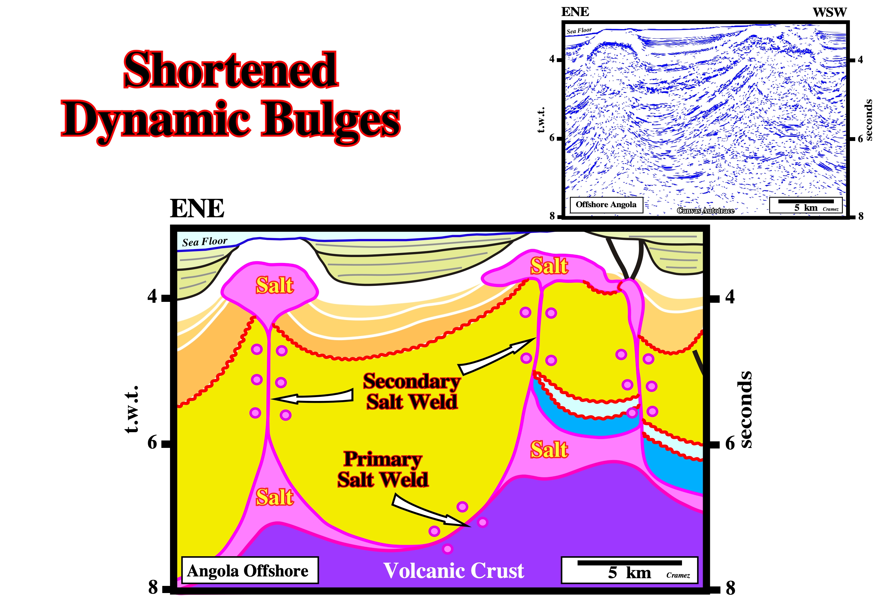
On Angola offshore, these salt structures have been interpreted as dynamic bulges shortened by a quite recent compressional tectonic regime that certain geologists associate with a significant ridge-push. The deformed onlap surfaces fossilizing the sedimentary interval overlying the bulge suggest the ridge-push still is going on.