

Ma (Geological age)
Millions years ago. Therefore, it expresses a geological age. Ma should not be confused with My, which means a period of time expressed in million years. Thus, SB. 30 Ma expresses the unconformity with age 30 M years ago, which is bounds a stratigraphic cycle, while 30 My expresses a period of time of 20 M years , which can be Paleozoic or Meso-Cenozoic.
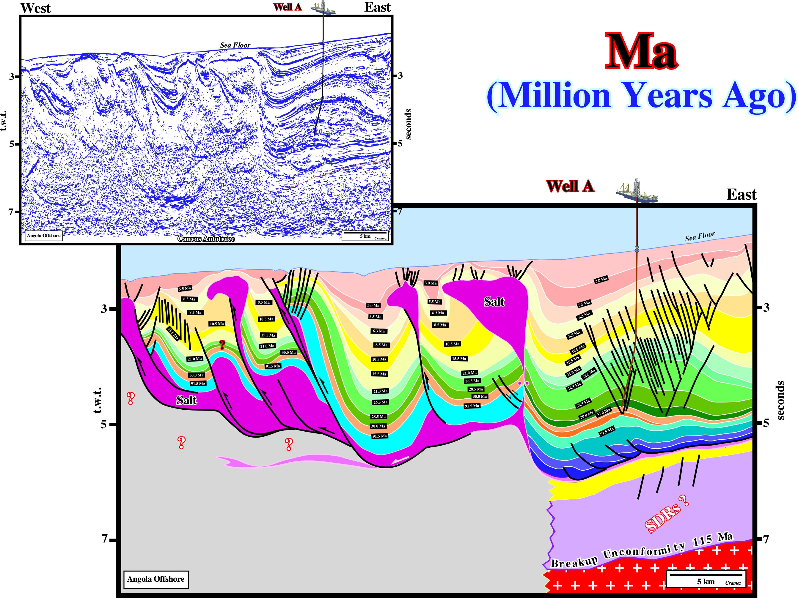
On this tentative geological interpretation of a Canvas autotrace of an Angola offshore seismic line, in which a discovery well was located, the unconformities (significant relative sea level falls) were dated, before drilling using the stratigraphic signature and the relative sea level curve of the area. The well's results do not falsify, too much, the tentative interpretation.
Mafic Igneous Rocks
Igneous rocks composed. chiefly, of one or more ferromagnesian, dark-colored minerals in its mode. The term igneous was proposed by Cross (1902) to replace the term femag, that is to say, a mnemonic term derived from ferric + magnesium. It is a complement of felsic.
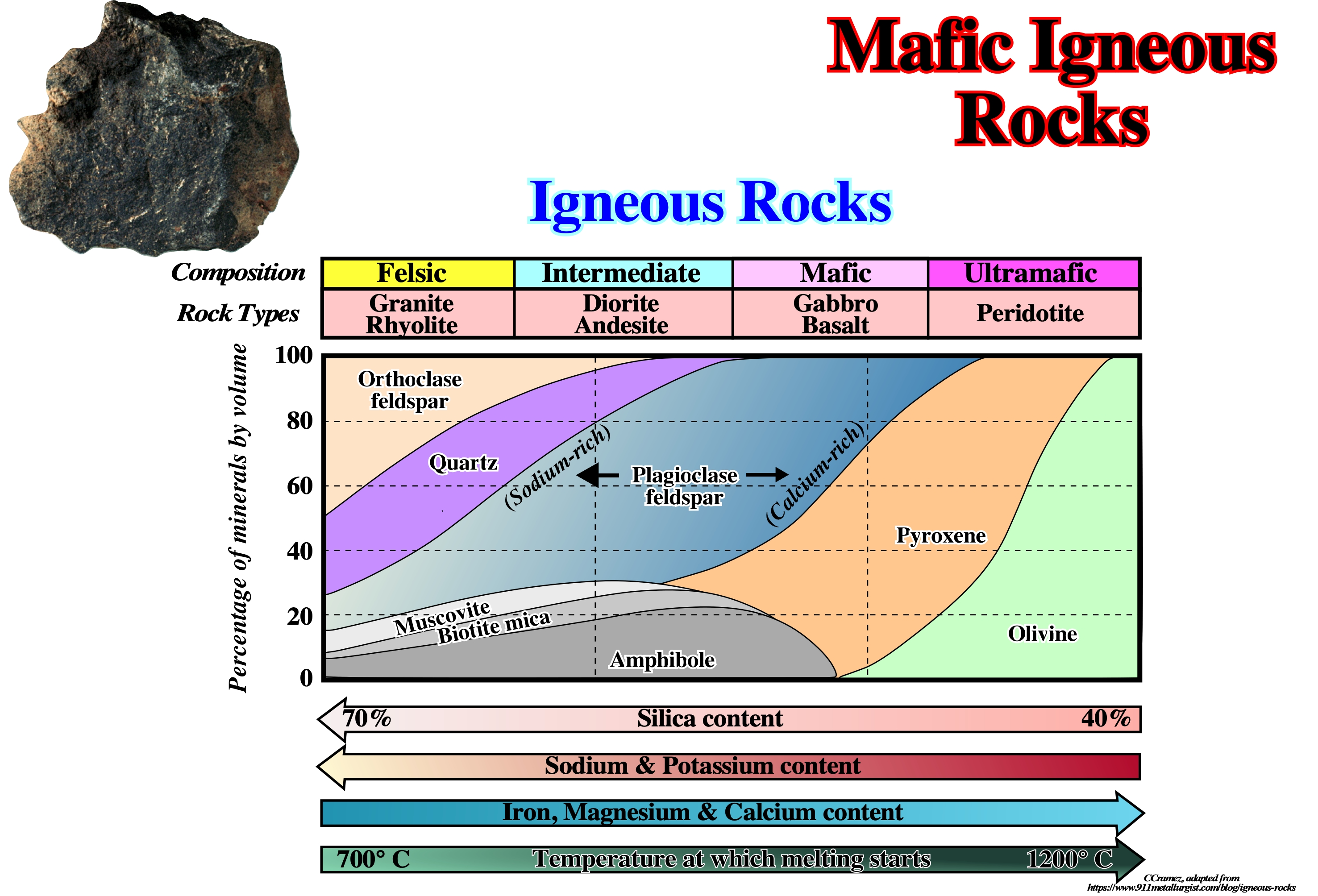
The picture above illustrates a mafic igneous rock, that in this particular case is a basalt. The term igneous was proposed by Cross (1902) to replace the mnemonic term femag.
Marginal Syncline
A withdrawal basin flanking elongated salt walls without a rim.
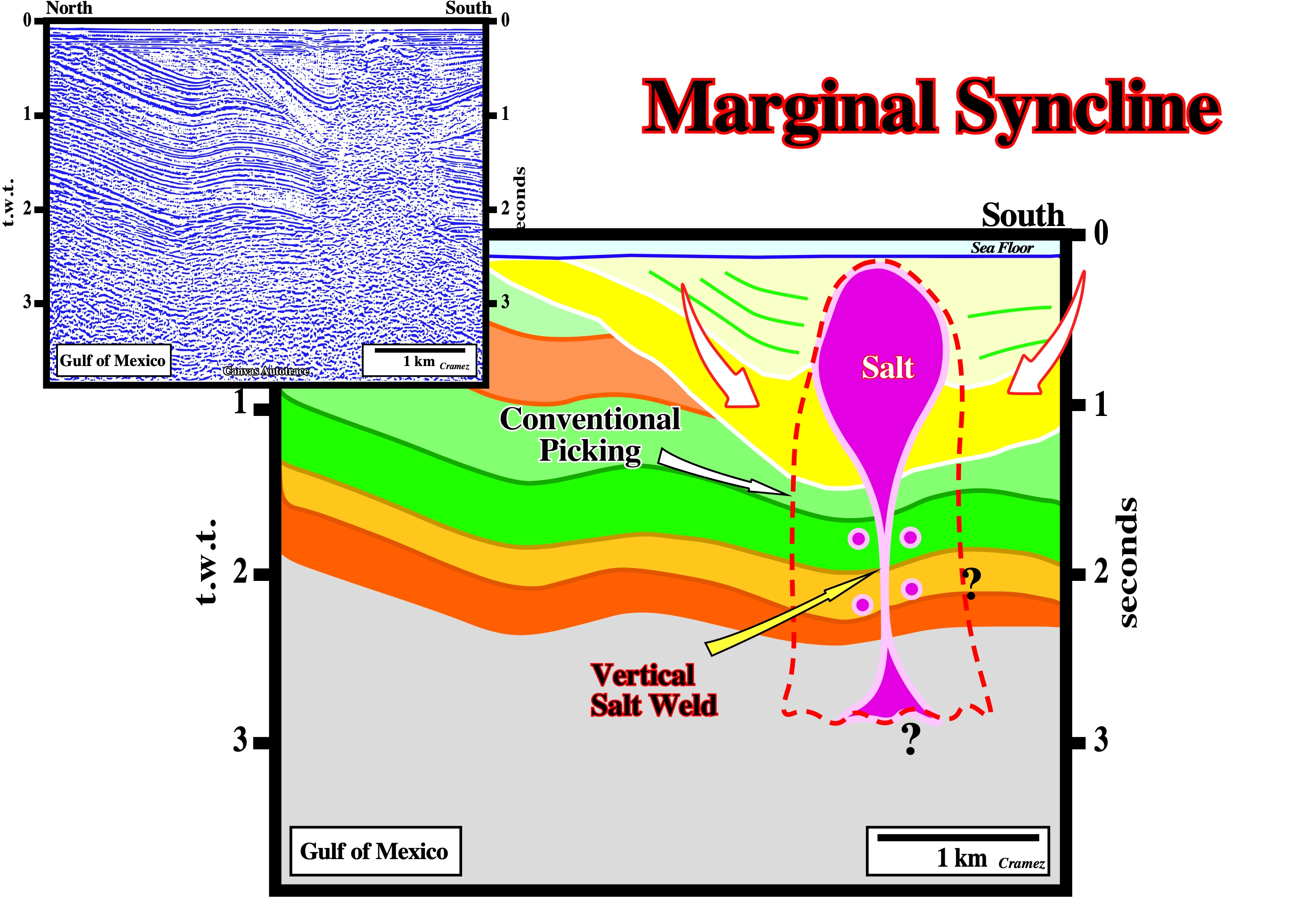
On this tentative interpretation of a Canvas autotrace of a GOM seismic line, synkinematic layers form the rim synclines, in each flank of the salt dome. The prekinematic layers are isopachous. Their thickness is roughly constant. A vertical salt weld connects the salt diapir with the mother source layer.
Mature Piercement
A diapiric growth by the diapir's stem necking after the adjoining source layer has been exhausted during the formation of a tertiary peripheral sink. Because salt supply is restricted, growth is slow and the diapir can easily become buried if sedimentation continues.
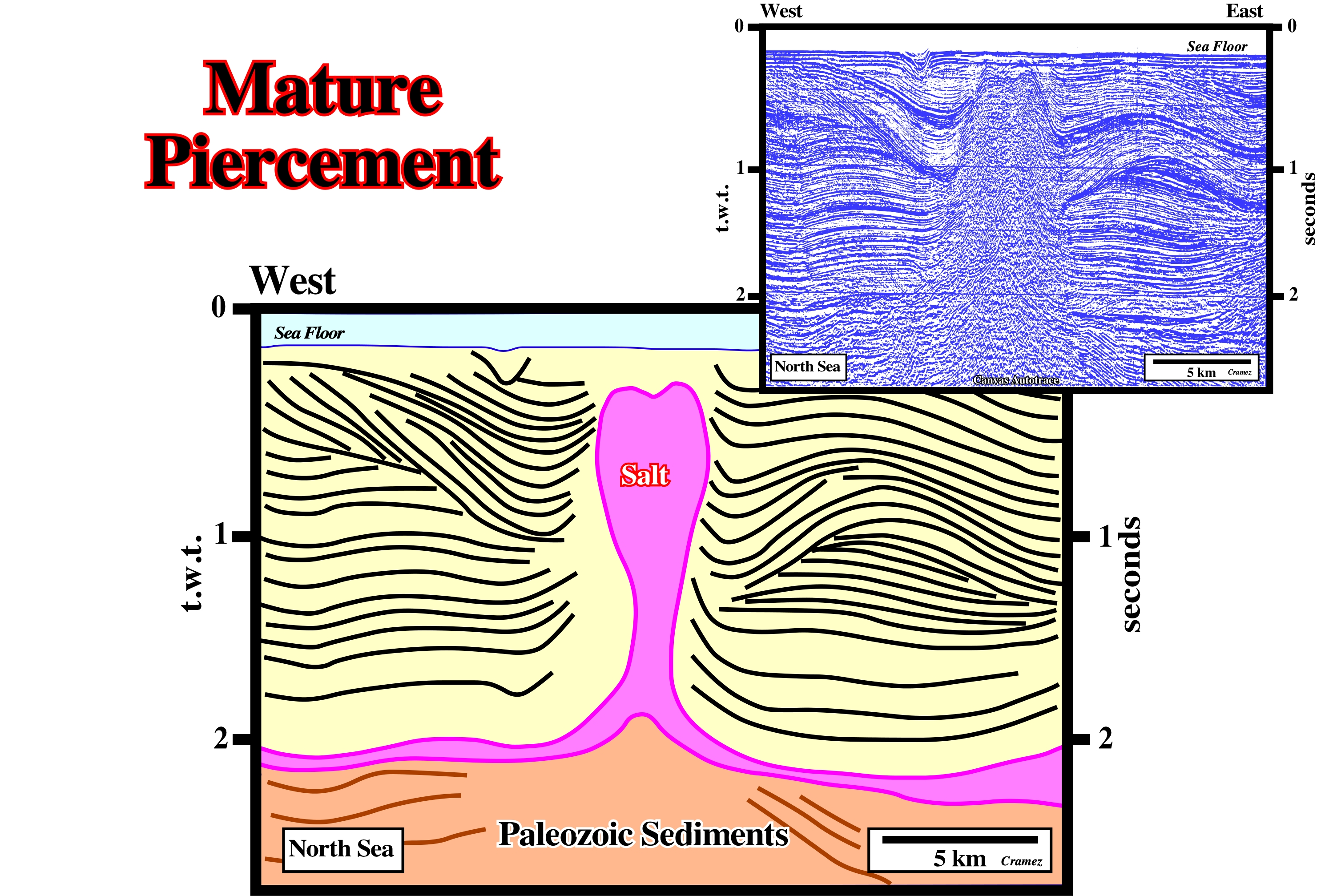
On this seismic line of South North Sea, the prekinematic and synkinematic layers of the overburden are obvious. The piercement is mature. The diapir is completely isolated from the mother source layer. A vertical salt weld individualizes the diapir from the autochthonous salt layer. Lateral pinched-off source layers are quite evident.
Maximum Effective Stress (σ1)
The maximum axis of the effective stresses ellipsoid. It can be vertical (extension) or horizontal (compression).
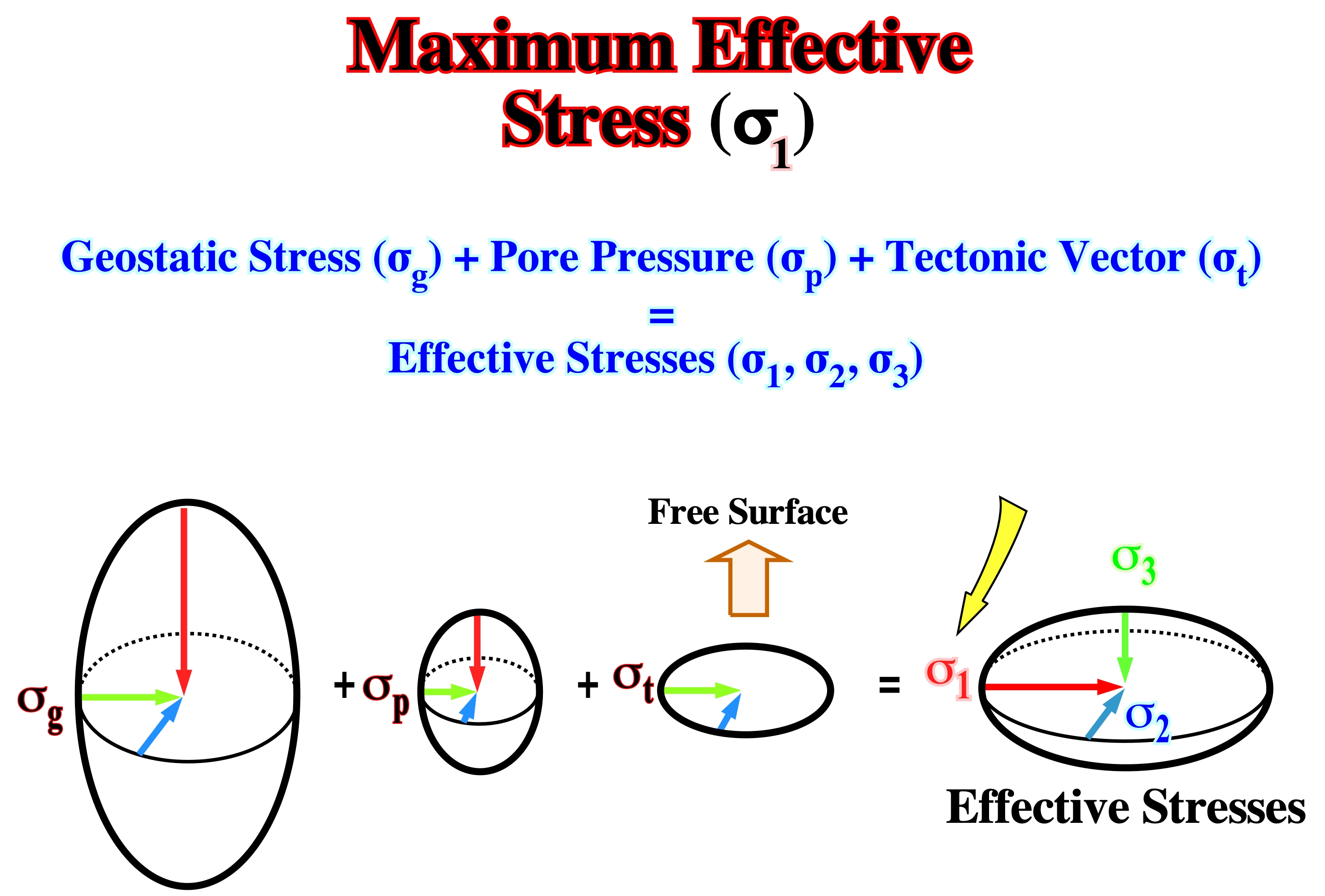
Conventionally, when the maximum effective stress, i.e., σ1 is vertical the sediments will be lengthened. When σ1 is horizontal the sediments will be shortened. The axis of the shortened structures are parallel to the σ1. Notice that σ1 (French terminology) corresponds to σ3 in English terminology.
Medium Effective Stress (σ2)
The medium axis of the effective stresses ellipsoid. It is along of this axis that faulting and fracturing takes place.
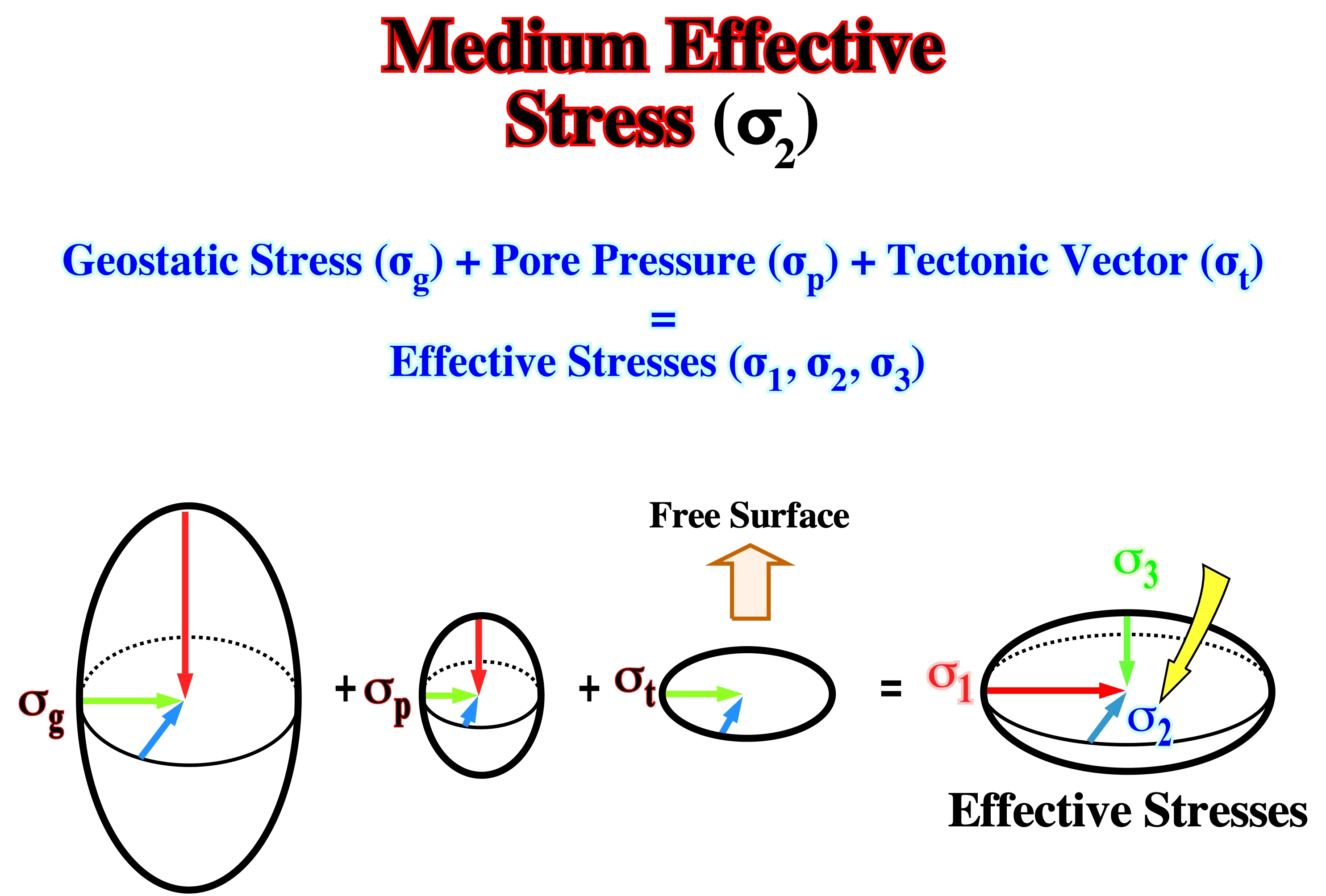
All faults strike parallel to the medium effective stress, σ2. If two fault systems (normal or reverse) strike in different directions, two medium effective stresses must be recognized. Therefore, one can say the area was affected by two tectonic regimes, one compressional and the other extensional.
Megasuture
Earth's mobile area (folded and faulted belts) evidencing the complexity of the accretion and deformation phases undergone by geologic bodies in areas where compressional tectonic regimes are preponderant.
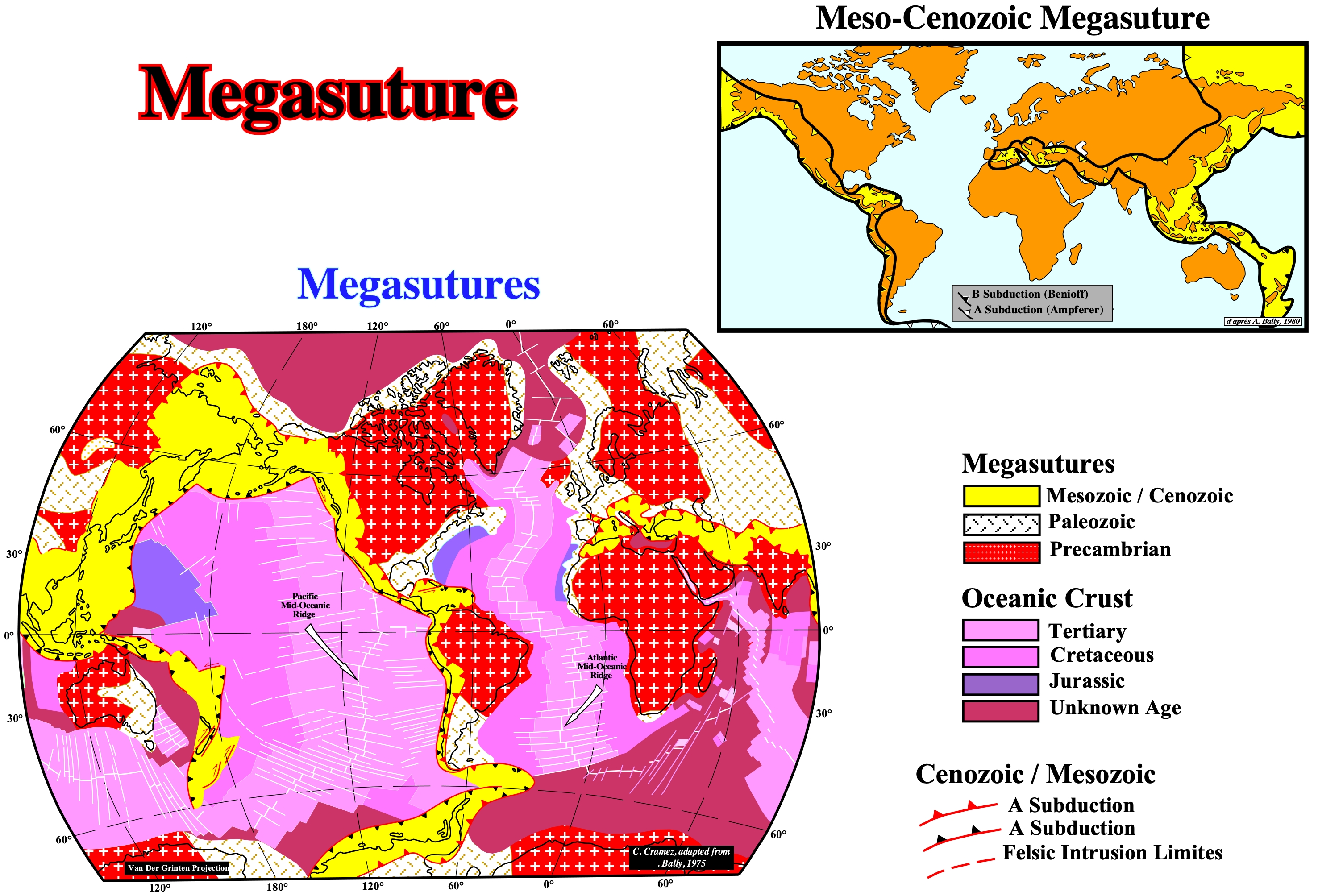
The Mesozoic-Cenozoic Megasuture is quite easy to map. Indeed, it corresponds to the post-Pangea fold-belts. Older megasutures (Paleozoic and Precambrian) are much more difficult to map. Subtle palinspathic reconstitution are necessary. The Mesozoic/Mesozoic megasuture is, as A. Bally (1980) said, the integrated product of all subduction processes that are contemporaneous with the Mesozoic/Cenozoic sea floor spreading (ocean expansion). Mesozoic/Cenozoic megasuture encompasses the folded belts, as well as the sedimentary basins they piggy-back basin. Mesozoic/Cenozoic megasuture can be visualized as a float orogen or as deformed sediments and fragments of the Earth's crust that were, mechanically, separated from their roots. Three megasutures are usually considered: a) Precambrian ; b) Paleozoic and c) Meso-Cenozoic. The most important limits of a megasuture are: (i) B-type subduction zones (or Benioff), which coincide with the subduction of the oceanic lithosphere ; (ii) A-type subduction zones (or Ampferer), which are outer boundaries of continents adjacent to folded belts, where a certain amount of continental lithosphere seems to disappear in depth by a mechanism similar to subduction ; (3) Limits dominated by strike-slip tectonics (such as in Californian basins) ; (iv) Limits poorly defined by felsic intrusions (as in China, Mongolia and Siberia). A megasuture can be considered as a suture formed by a Continent/Continent (between two continents) or Continent/Volcanic Arc (between a continent and a volcanic arc, created by a B-type subduction zone) with, more or less, of the metamorphic granite substrate. The Mesozoic/Cenozoic megasuture encompasses all the geological bodies associated with the subduction phenomena (A and B type) that have occurred since the Permian/Triassic until today. It represents the response to the sea floor spreading that accompanied the dispersion (cause or effect) of the continents formed by the breakup of the Pangea supercontinent. It encompasses all products of orogenic and igneous activity following the breakup of the Pangea supercontinent and associated sedimentary basins, in particular the episutural basins and mountain ranges. As can be seen above, the Paleozoic megasuture now consists, exclusively, of continental crust and A type subduction zones (Ampferer). The absence of Paleozoic oceanic crust is explained by a very intense B type (Benioff) subduction mechanism that would have consumed almost all the oceanic crust of that age. Also, the orogenic zone that constitutes the Precambrian megasuture does not also show evidence of Archaeozoic oceanic crust. Bally used the concept of megasuture to classify the different domains of subsidence. It divided the sedimentary basins into two large groups: (i) Basins not associated with megasuture formation i.e., basins associated with the formation of a new oceanic crust (cratonic, rift-type, Atlantic and non-Atlantic type continental margins) and (ii) Basins associated with megasuture formation, in which he considered two families: (a) Perisutural basins, i.e., formed in the periphery of the megasuture (forearc basins, foreland basins, etc.) and (b) Episutural Basins, i.e., basins formed within megasuture (backarc basins, Pannonian basins, Mediterranean basin, folded belts, etc.). The concept of megasuture is based on the basic principles of plate tectonics, which can be summarized as follows: 1) The outer and rigid layer of the Earth is a mosaic of tectonic plates that move relative to each other ; 2) The plates are born at the level of the mid-oceanic ridge and float on the asthenosphere ; 3) The plates move away without deforming ; 4) The new oceanic crust, continually, moves away from the axis of the mid-ocean ridges, and as it approaches the continents, it is destroyed along the B type subduction zones ; 5) The continents are, generally, considered as passive objects carried by the spread of the ocean floor ; 6) The continents or blocks of the continental crust can collide and create large continents ; 7) The boundaries of the plates are constituted by mid-ocean ridges, subduction zones and transforming faults ; 8) The internal energy of the globe dissipates in the limits of the plate ; 9) The relative movements of the plates are governed by the mathematical laws of kinematics on a sphere.
Mesozoic
See: Mesozoic-Cenozoic.
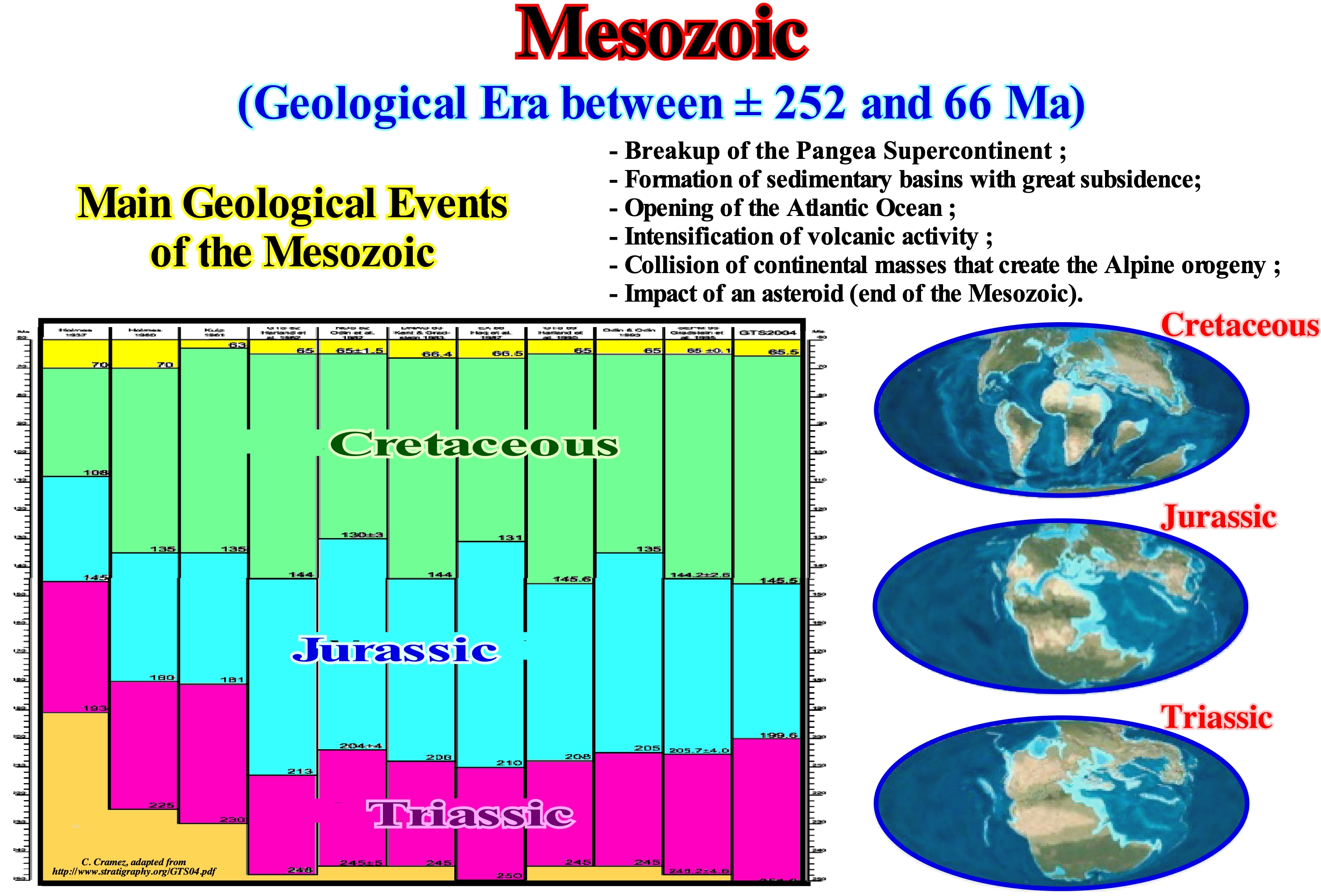
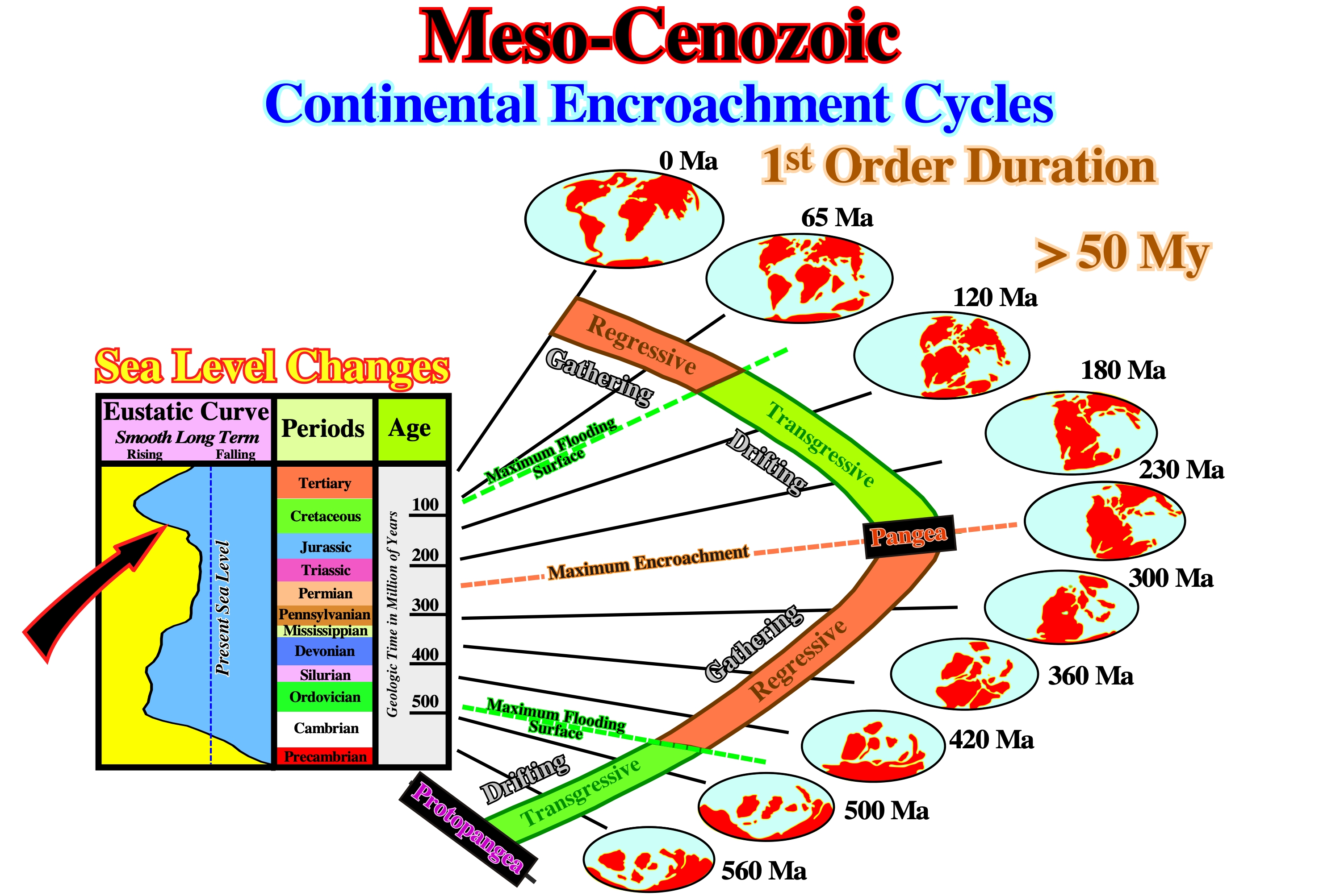
The Mesozoic is divided into three periods: (i) Triassic, which lasted more or less 35 My, between 245 and 208 Ma ; (ii) Jurassic, which lasted approximately 62 My, between 208 and 146 Ma and (iii) Cretaceous, which lasted about 81 My, between 146 and 65 Ma. The Mesozoic, which in etymological terms means average life (animals), is the time during which the terrestrial fauna changed, drastically, in relation to the Paleozoic fauna. Dinosaurs, which are perhaps the most popular organisms of the Mesozoic, developed in the Triassic, but until the Jurassic, were not very diversified. Except for birds, the dinosaurs died out at the end of the Cretaceous. The Mesozoic was, also, a time of great change of terrestrial vegetation. At the beginning of the Mesozoic, the foetuses, cicadas, ginkgophytes and other plants, that today are not very common, were predominant. Modern gymnosperms, such as conifers, appeared in their most recognizable form at the beginning of the Triassic. Around the middle of the Cretaceous, appeared the first angiosperms, which began to diversify, surpassed all other types of plants. In terms of sequential stratigraphy, it can be said the Mesozoic corresponds, roughly, to the absolute (eustatic) sea level rise induced by the dispersion of the continents resulting from the breakup of the Pangea supercontinent, i.e., the rise of sea level of the first order eustatic, which began with the Pangea breakup. It was from the Cenomanian-Turonian that the eustatic sea level began to fall. The Mesozoic corresponds, roughly, to the transgressive phase of the continental encroachment stratigraphic cycle, which is characterized by sedimentary intervals with a retrogradational geometry, which explains the progressive increase of the depositional water-depth, as the extension of the continental shelves was growing. More rigorously, as said before for the rise of sea level, from the Cenomanian/Turonian, that is, from downlap surface 91.5 Ma, the geometry of the Mesozoic sedimentary intervals ceases to be retrogradational to become, predominantly, progradational, since, globally, the absolute sea level began to fall.
Mesozoic-Cenozoic
Post Pangea continental encroachment stratigraphic cycle deposited during the younger first order Phanerozoic eustatic cycle.
The Phanerozoic Eon is composed by three Eras (i) Paleozoic, (ii) Mesozoic and (iii) Cenozoic. The Mesozoic corresponds to the older post-Pangea eustatic cycle, while the Cenozoic corresponds to the younger post-Pangea cycle.
Messinian Salt
Salt deposited during the geological event in which the Mediterranean Sea entered a partial cycle of dissection, completely, or almost during the last part of Messinian. The salt crisis ended with the Zanclian ingression (Zanclian flood of certain geoscientists), when the Atlantic Ocean returned to enter the basin of the Mediterranean ocean.
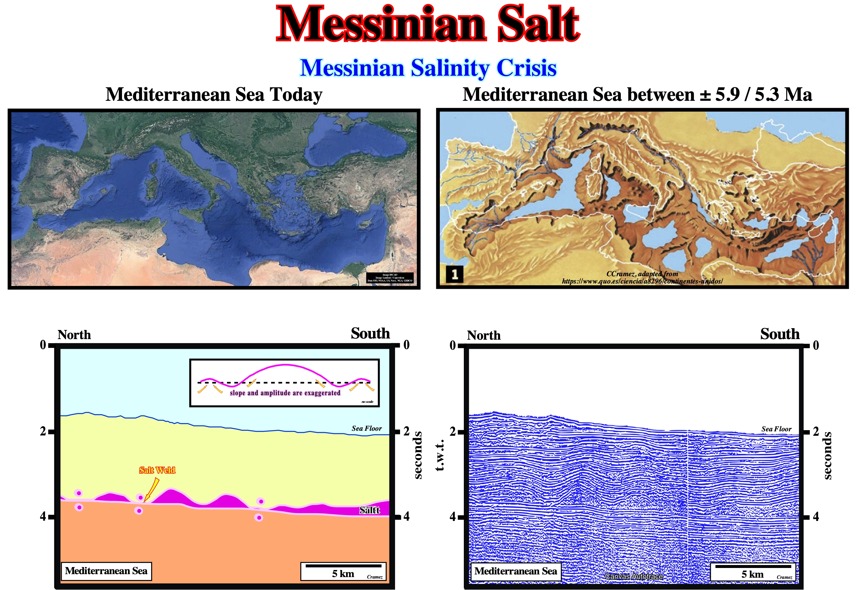
The Messinian drying of the Mediterranean sea seems rather of tectonic origin than a consequence of the Plio-Pleistocene glaciation. It was, probably, due to the gradual closure of the Strait of Gibraltar as a result of the northward movement of the lithospheric African plate. This closure prevented eustatic rebalancing with the Atlantic Ocean and led, locally, to to a drop in sea level of about 1,500 to 2,500 meters. At the rate of 3,300 km 3/year of net evaporative loss, the Mediterranean geographic basin (3.7 Mkm3) dried up roughly in 1,000 years, leaving a salt layer with some tens meters thick (decreasing the average salinity of the the world ocean and rising its freezing point) and rising the absolute sea level around 12 meters (the evaporated water reached the oceans when it fell as rain or snow). On the left part of the tentative interpretation of a Canvas autotrace of Mediterranean line, Messinian salt anomalies (undulations) are easily recognised. They have a, more or less, similar amplitude, which seems to be big enough to break, by traction, the bottom of the overburden, particularly when its facies is compact sandstones or carbonates.
Metamorphic Rocks (McNeill, L. et al., 1999)
A group of gneiss and crystalline schists (originally used by Lyell, 1833, see below).
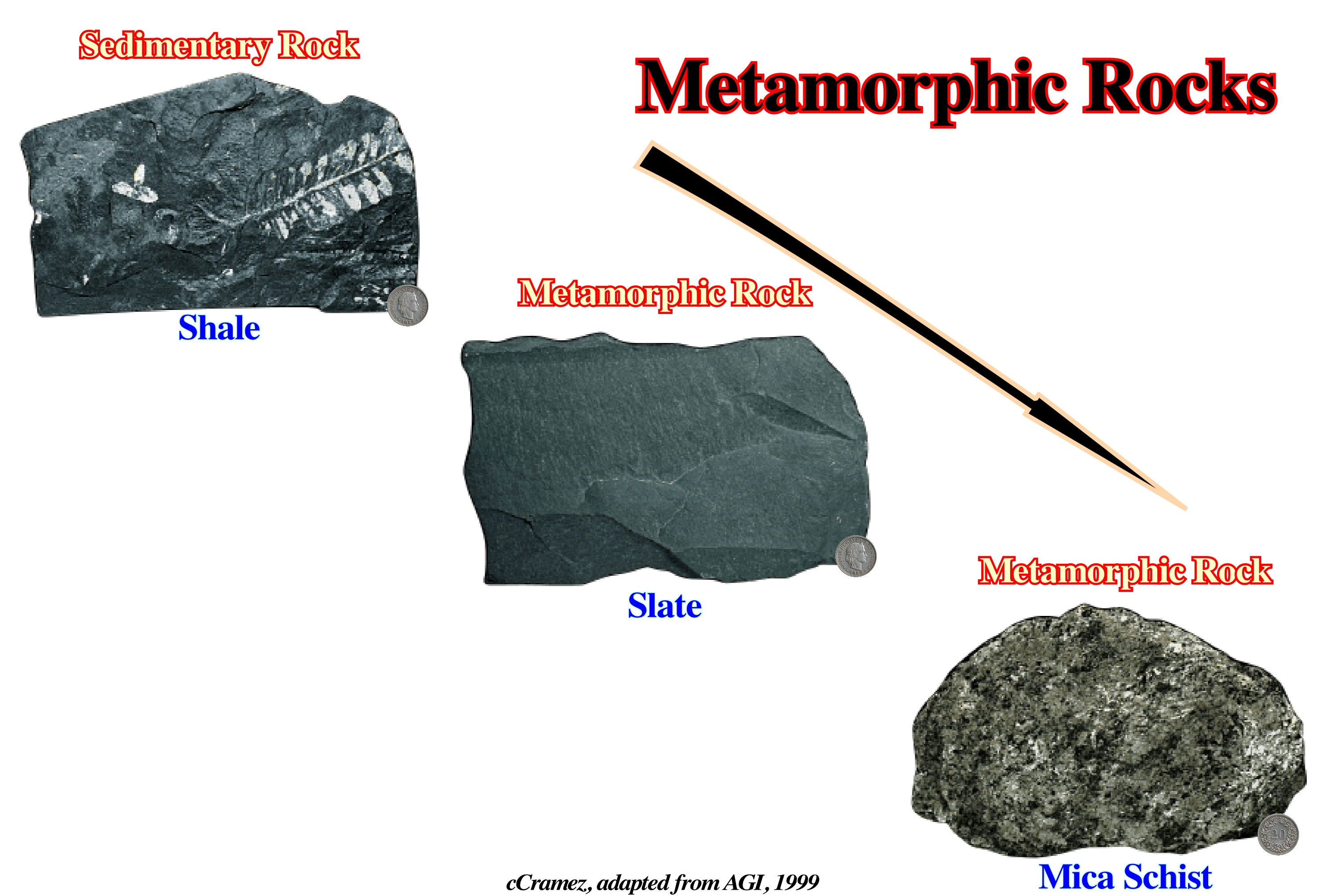
Currently, metamorphic rocks express any rock derived from pre-existing rocks by mineralogical, chemical and/or structural changes, essentially in the solid state, in response to marked changes in temperature, pressure, shearing stress, and chemical environment, generally at depth in the Earth's crust.
Mini-Basins
Synonym of Salt expulsion basin.
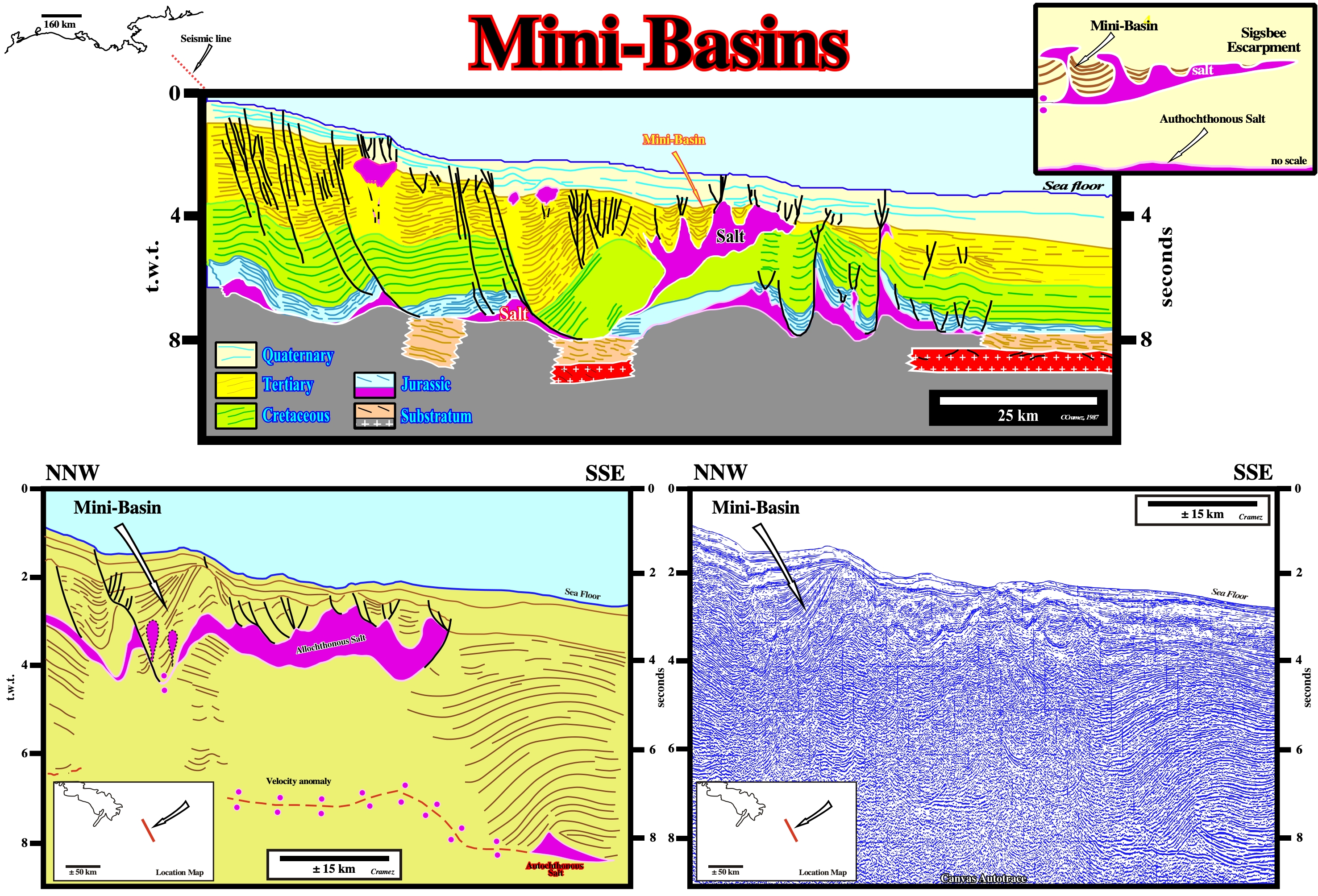
The term mini-basin is used, mainly, to express to salt expulsion basins associated with allochthonous salt. The intelligence of the mini-basins is, easily, found on these tentative geological interpretation of Canvas autotraces of seismic lines of Gulf of Mexico, by compensatory subsidence of the allochthonous salt induced by a total or partial lateral salt movement.
Minimum Effective Stress (σ3)
The minimum axis of the effective stresses ellipsoid. It is orthogonal to σ1 and σ2. It is along this axis that deformations take place, i.e., folding or faulting
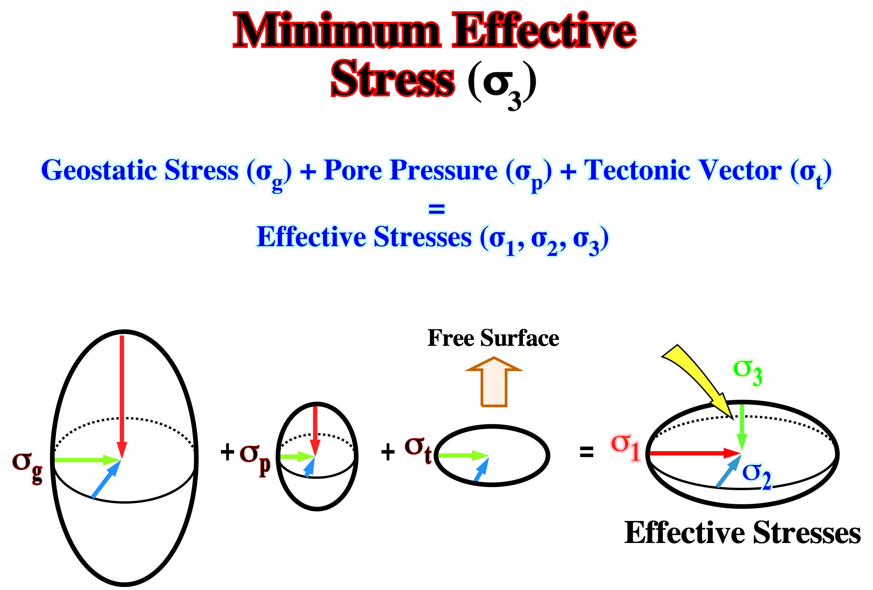
In an extensional tectonic regime, the minimum effective stress is perpendicular to the strike of the faults. The direction of the σ3 is the direction along which lengthening or extension takes place. In a compressional tectonic regime, the σ3 is the direction along which deformation takes place.
Mobile Substratum
See: Substratum.
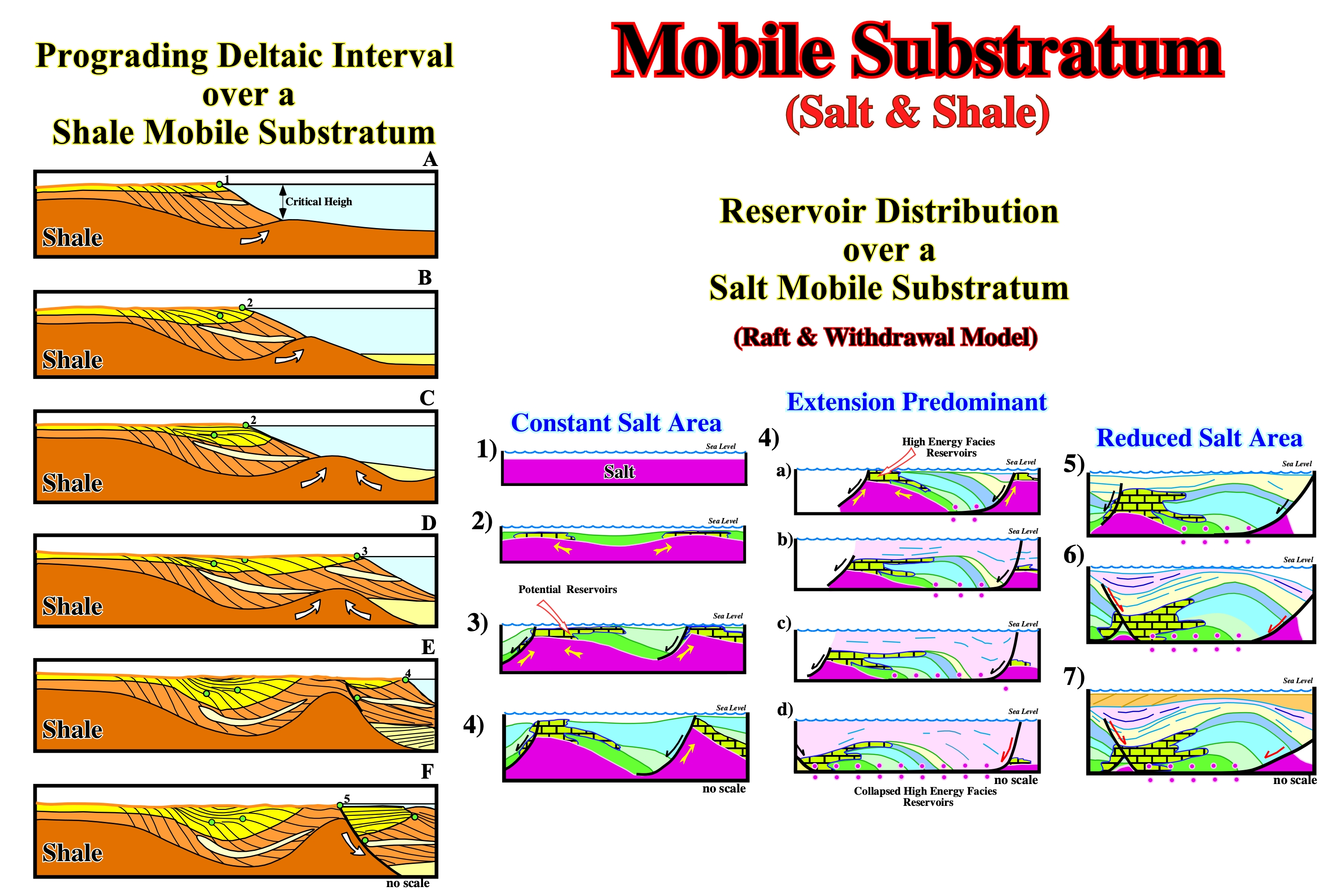
The seaward progradation of sedimentary environments and development of growth faults, associated to shale tectonics, can be translated by "Aggradate ut Progrademus", i.e., upbuilding is required to outbuilding. Let's see what that means when a deltaic interval prograding over a mobile shaly substratum. (i) During the stage A, in which the thickness of deltaic platform is between 20-150 m, the shoreline (depositional coastal break) progrades over the shale substratum (the continental or deltaic slope is stable) ; (ii) The shoreline and continental sands prograde seaward, at the same time that proximal turbidites and slope shales are deposited ; (iii) This mechanism creates a sedimentary depocenter which increases, locally, the vertical stress σ1 (lithostatic pressure minus pore pressure) (iv) As σ3 is horizontal and perpendicular to the shoreline (σ2), the mobile substratum starts to flow seaward and upward developing a mound and creating a compensatory subsidence in the onshore ; (v) The first consequence of the mound developing is the increasing of the slope angle, which becomes unstable to a certain depth water deposition, critical depth (HC) ; (vi) At that time, the sediments can not prograde because the slope is unstable, that is, it does not allow deposition ; (vii) Thus, more the substratum flows upward, more thick is the onshore depocenter and, as the slope is unstable, the sediments arriving to the shoreline are transported basinward by turbiditic currents, being deposited when the currents decelerate ; (viii) The result is a turbiditic upbuilding package deposited under a great water depth (During this time, stage B, the shoreline (2) does not change) ; (ix) The turbiditic upbuilding package, deposited in the bottom of the slope induces a new shale flowing which decreases the slope angle (at this stage of the tectonic evolution, the main event is the reduction of the angle of slope which becomes stable) ; (x) When the slope angle is stable, the progradation of shoreline and deposition of continental sands and slope shales is possible (stage C): "Aggradate ut Progrademus" (xi) The consequence of this seaward progradation is the displacement of the shoreline from 2 to 3, and thickening of the onshore (stage D) ; (xi) The consequence of this seaward progradation is the displacement of the shoreline from 2 to 3, and thickening of the onshore (stage D) ; (xii) As the evolution continues at a certain time, two big sedimentary depocenters will be developed landward and seaward of the shale dome ; (xiii) The pressure against the shale dome increases more and more, and the flanks of the shale dome become steeper ; (xiv) The seaward flank of the dome (due to the orientation of the tectonic stress σ3) becomes unstable and a fault zone starts to develop close to the top of the dome but in seaward flank (stage E) ; (xv) The exaggeration of this instability creates a typical gliding plane along the flank of the shale dome and a growth fault is developed with a thickening of the sediments against the fault plane and a slight transgression displaces the shoreline landward (5). It is the stage F. Three remarks must be made: a) A shale mobile substratum implies a high pore pressure ; he water pressure reduces the effect of the normal stress on the gliding plane and so reduces the frictional resistance gliding ; b) - This mechanism requires a strong terrigeneous influx, and it is the reason why this kind of structures are frequently associated with river dominated deltas (proximal turbidites are developed by the same mechanism, just the scale and the upbuilding change). Total’s geoscientists proposed raft-tectonics with salt withdrawal to explain structures and reservoirs facies distribution of the Pinda formation in Angola offshore. Roughly, in the raft tectonic model (left part of the figure), the carbonate sedimentation is mainly controlled by the halokinesis thereby the reservoir facies are deposited over salt structural highs. Due to salt withdrawals and lateral salt flowage, structural inversions are formed and the initial structural high areas become structural lows. The success of this salt tectonic model was mainly associated with the discoveries of several oil fields. Nevertheless, since then the model could not explain all carbonate structures and reservoir distribution. It was, partially ,refuted by new geological and geophysical observed data.
Mohr-Coulomb Fracture Criterion
Failure during frictional plastic deformation follows the Mohr-Coulomb fracture criterion where one should take into account the shear strength, the cohesive shear strength, the normal stress, the angle of internal friction or slope of Mohr's envelope and the Coulomb coefficient.
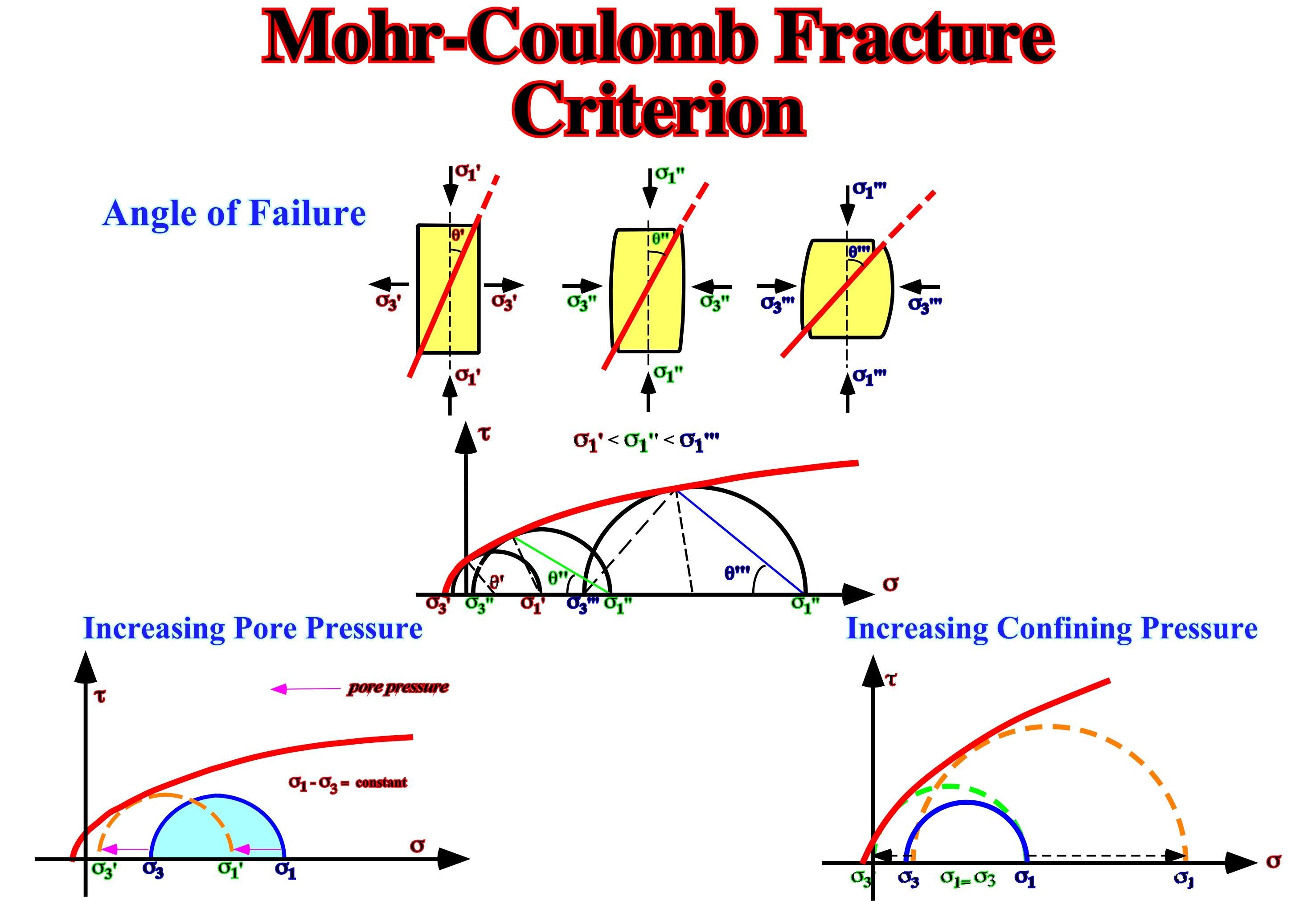
The angle of failure increases with the burial of the sediments. As sediments are buried, σ1 and σ3 increase as well as the angle of failure as illustrated above. The evolution of the failure angle explains why the angle of the faults planes increases in depth, i.e., fault planes flattened in depth. The increasing of pore pressure promotes failure. When the confining pressure increases (σ3 up), the failure stress increase (ductile rocks). Detachment planes, slopes failures and slumps, etc., can be explained by an increasing of the pore pressure. This Mohr’s envelope illustrates the increasing of the confining pressure, which induces the stress-failure.
Mohr's Envelope
Envelope of Mohr's circles. The Mohr’s theory hypothesizes that the normal stress, in compression or tension, plays a role in the failure as well as the tangential stress. Their relationships can be determined experimentally. The graphic representation of the stresses by circles allows to determine the Mohr’s envelope. As the tri-dimensional realm of the stress can be represented in a plane and the intermediated stress does not have any influence, the Mohr’s envelope can be determined by the maximum and minimum effective stresses.
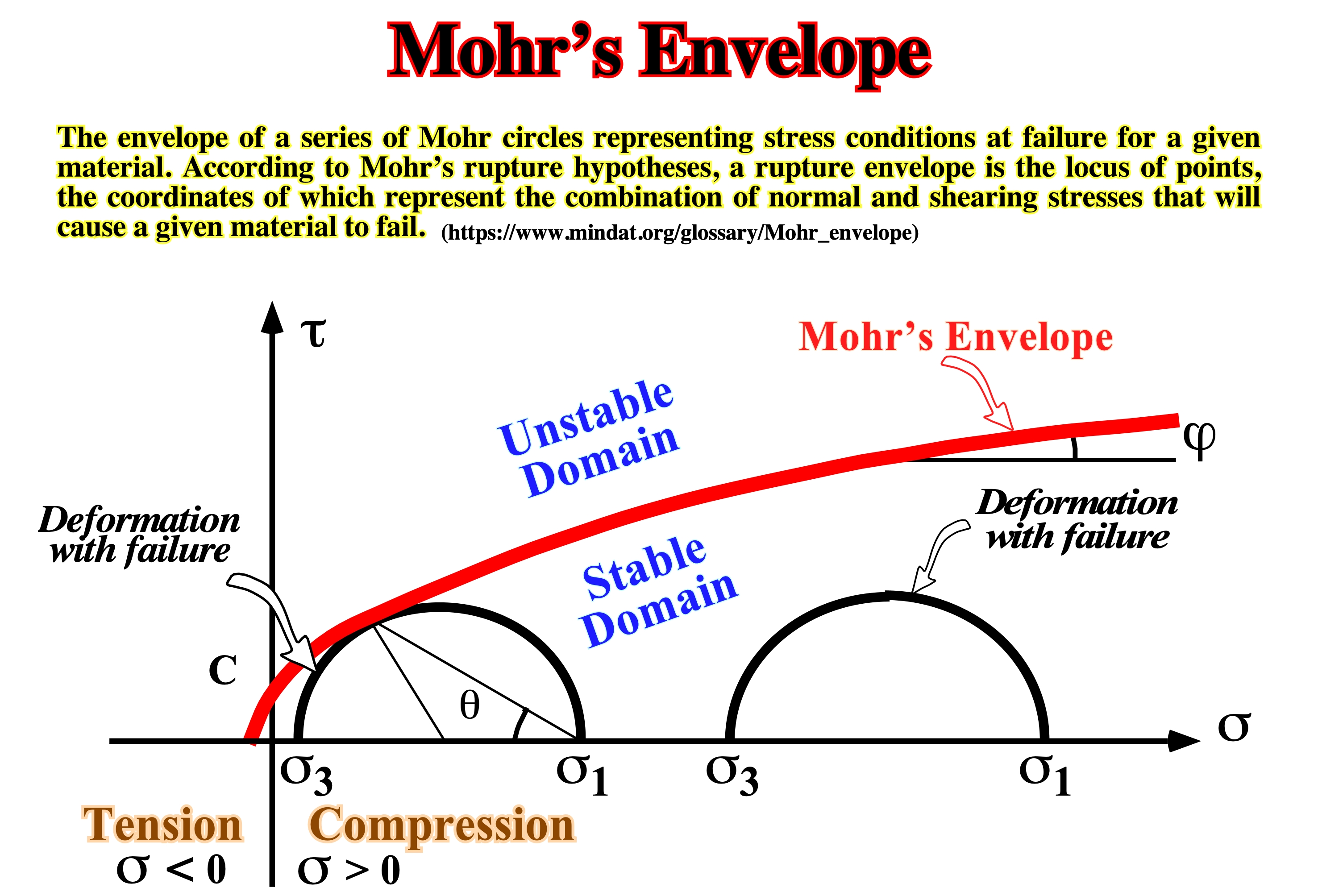
Hypothesizing that all planes, under the same normal stress failure, along the same plane containing the maximum tangential stress, the intermediate stress can be neglected. The same can be achieved by using a series of tests made under varying combinations of σ1, σ2, σ33, including uniaxial compression and uniaxial tension. The results of these tests can be referred to a set of coordinates by drawing Mohr's circles. Since these tests represent failure conditions, the envelope of the circles drawn so that it is tangent to each circle, represents the function: t =F(σ). The Mohr’s envelope intersects the shearing axis at a value C called the cohesion of the material, which must be overcome priori to the development of a fracture plane.
Molding Models (Talbot, C. J., 1995)
A profile of the diapir entirely downbuilt in effectively. Although active diapirs must deform the overburdens they pierce, the shape of passive diapirs is formed or molded by their overburdens. The dips of salt-sediments contacts are shaped by the interaction of two processes: (i) local net accumulation of overburden (A= deposition-minus compaction) at rate Å and the net increase relief of salt structures (R=salt rise-minus dissolution) at rate R°.
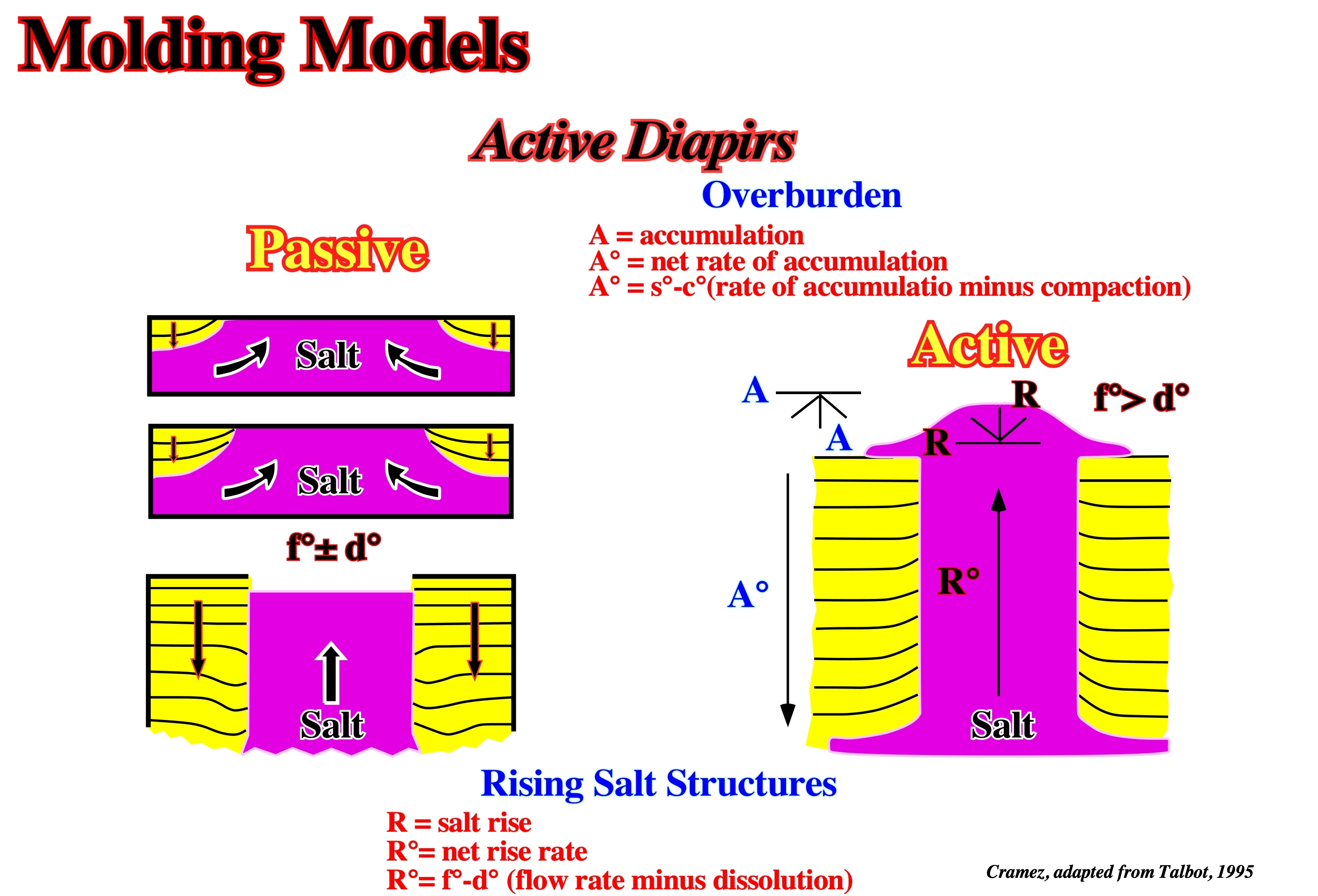
In a passive piercement, salt diapirs downbuilding with crests that remain emergent as their overburden accumulates around them. In contrast to active diapirs that deform overburden already in place, the shapes of passive emergent diapirs are molded by stiff overburden. The net local accumulation, A, of effectively rigid clastic sediments occurs at rate A° (rate of aggradation minus compaction). The relief of salt diapirs, R, downbuilding by stiff overburden occurs at rate R° (flow rate of salt minus dissolution). It is assumed that both salt and sediment spread sideways as fast as they rise or accumulate respectively.
Molding Ratio (Talbot, C. J., 1995)
The kinematic ratio R°/A°, where R° is the flow rate of salt minus dissolution and A° is the rate of aggradation minus compaction.
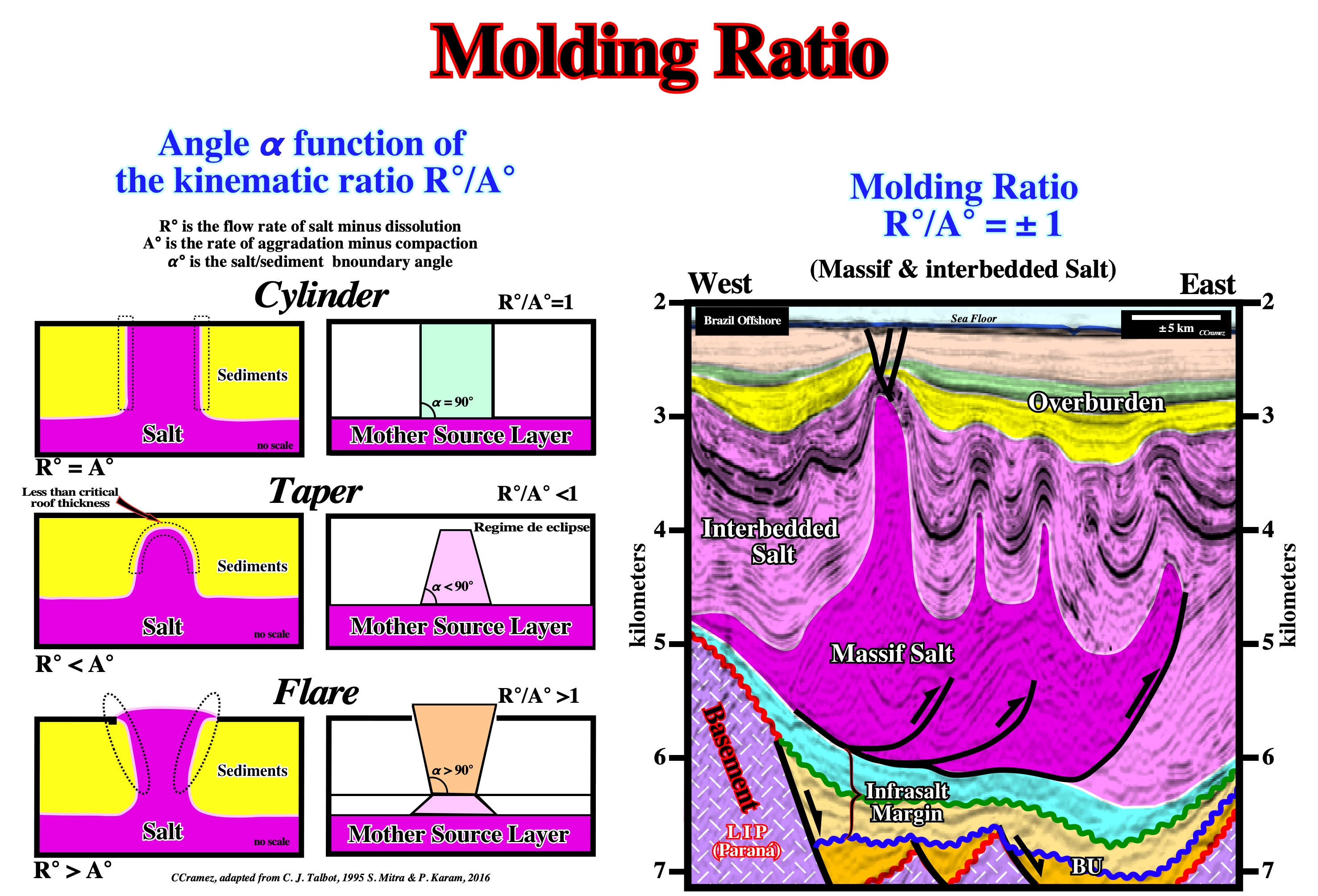
Theoretical three salt/sediment boundary angles are recognized function of the molding ratio. (i) Cylinder (R°/A° = 1), structures with flanks more or less vertical ; (ii) Taper ((R°/A° < 1) when the flanks are, roughly, convergent upward and (iii) Flare ((R°/A° > 1), when the flanks of the salt structures are divergent upward. Thus, on the tentative geological interpretation of a seismic line of Brazil offshore, the salt (massif and interbedded) antiform structures can be considered as cylindrical, which seems imply that the molding ratio (R°/A°) is near 1.
Monoclinic System
One of the six crystal systems, characterized by either a single twofold axis of symmetry, a single plane of symmetry, or a combination of the two. Of the three nonequivalent axes, one is perpendicular to the plane formed by other two.
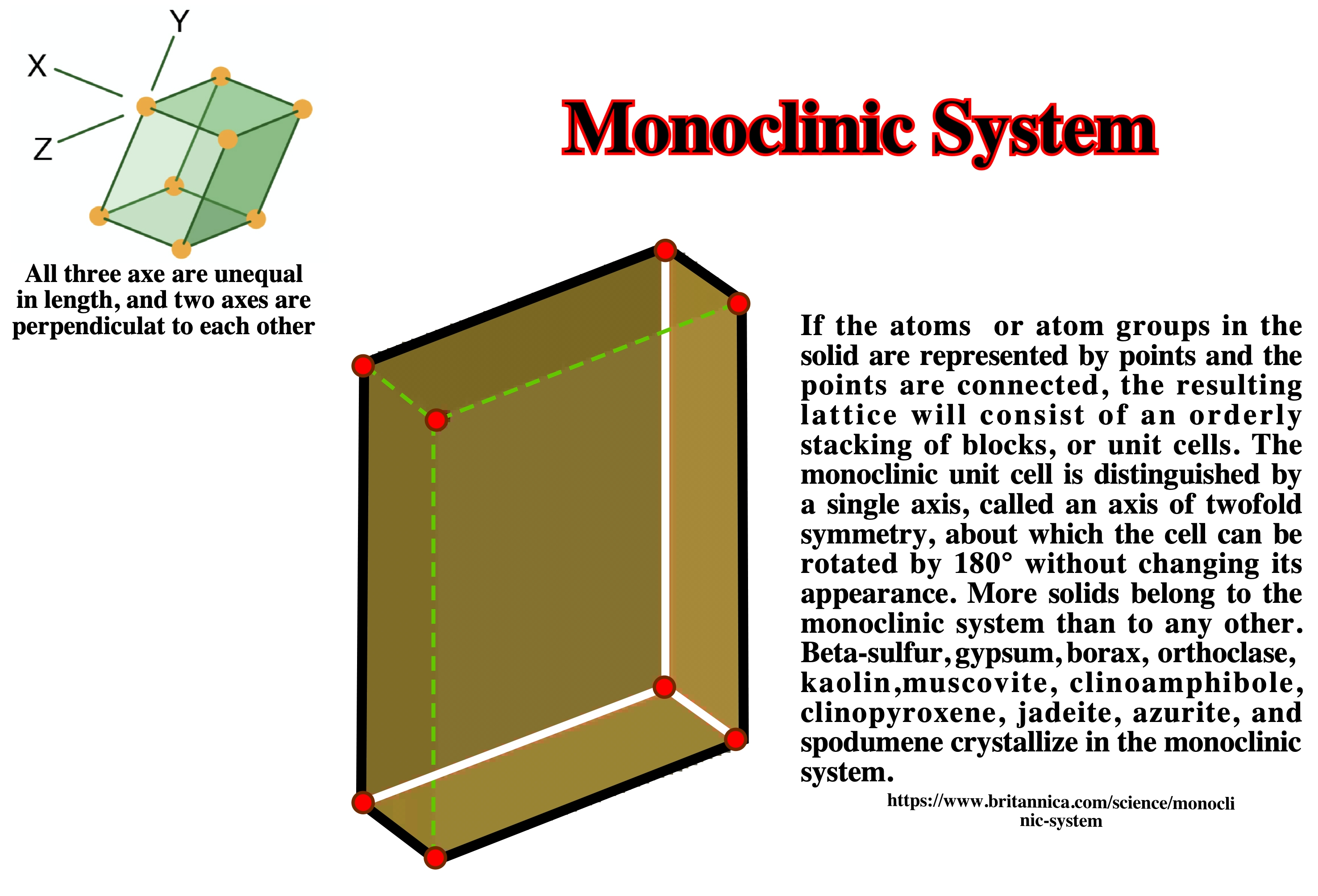
One the three nonequivalent axe is perpendicular to the plane formed by other two.
Mother Diapir
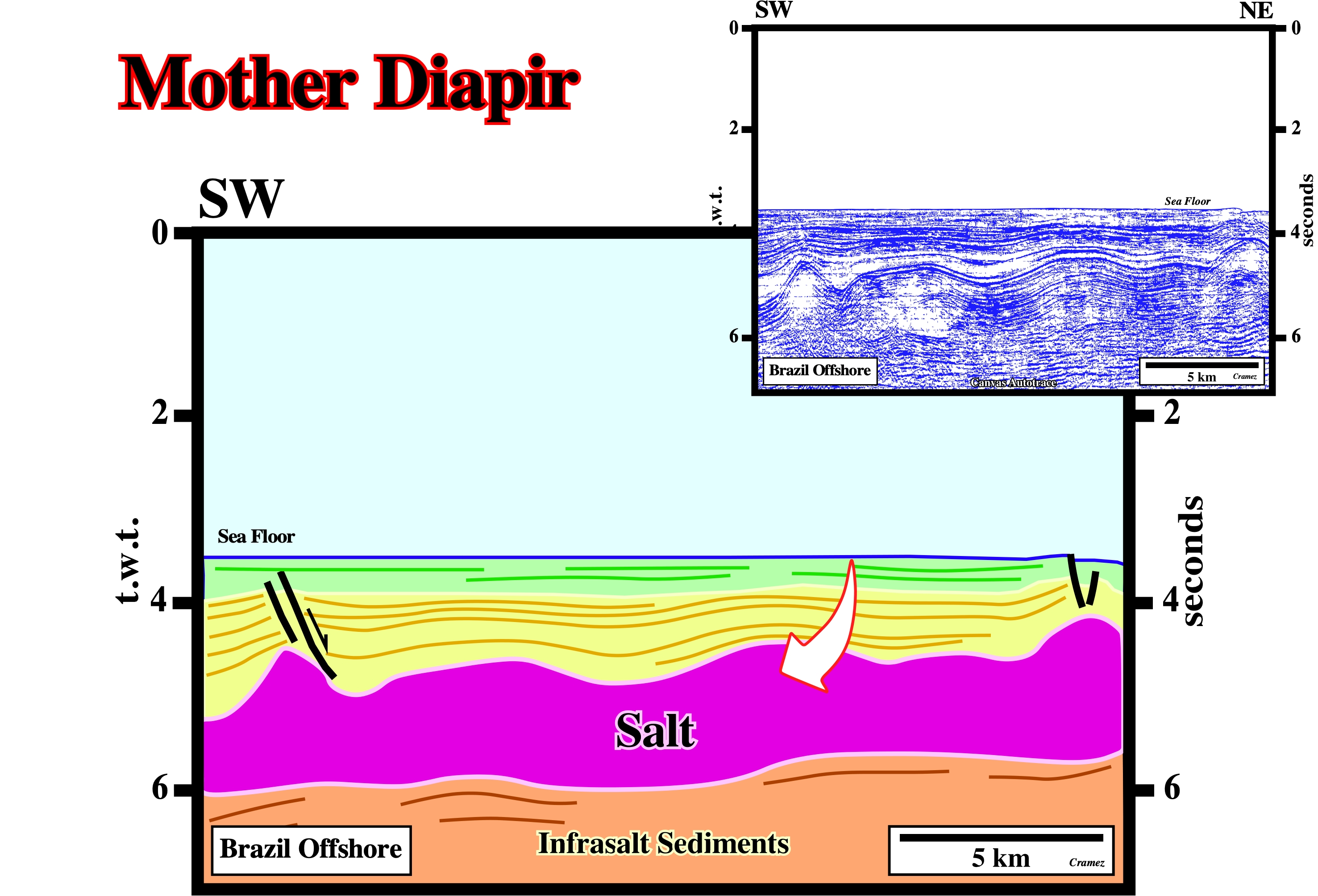
On this tentative interpretation of a Canvas autotrace of a Brazil seismic line, the small anomalies on the top of the allochthonous salt can be considered as the initiation of a first generation salt walls or stocks.
Mother Salt Layer
Synonym of Source layer.
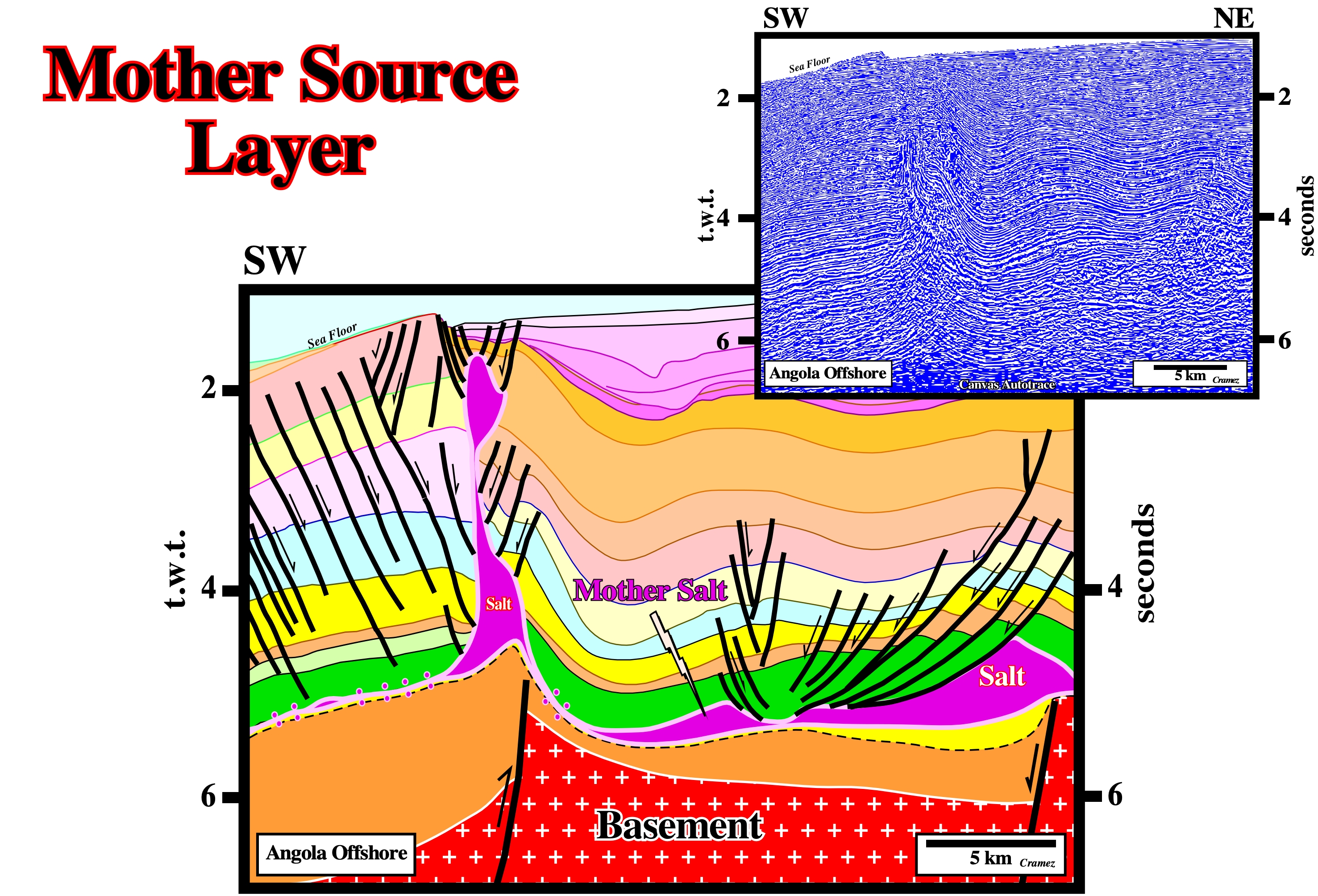
Generally, the mother source layer is easy to recognize. When it is reduced to a salt weld, the identification of the associated tectonic disharmony is necessary. When thick allochthonous salt layers are present, the recognition of the deep autochthonous salt is almost impossible even in pre-stack depth migrated data.
Mound Stage
Differential subsidence (compensatory subsidence) induced by salt flowage creates: a) an uplifted area (mound), where the subsidence is less and therefore where the stratigraphic intervals are thinner and b) depocenters around, in which the stratigraphic intervals are thicker (figure below).
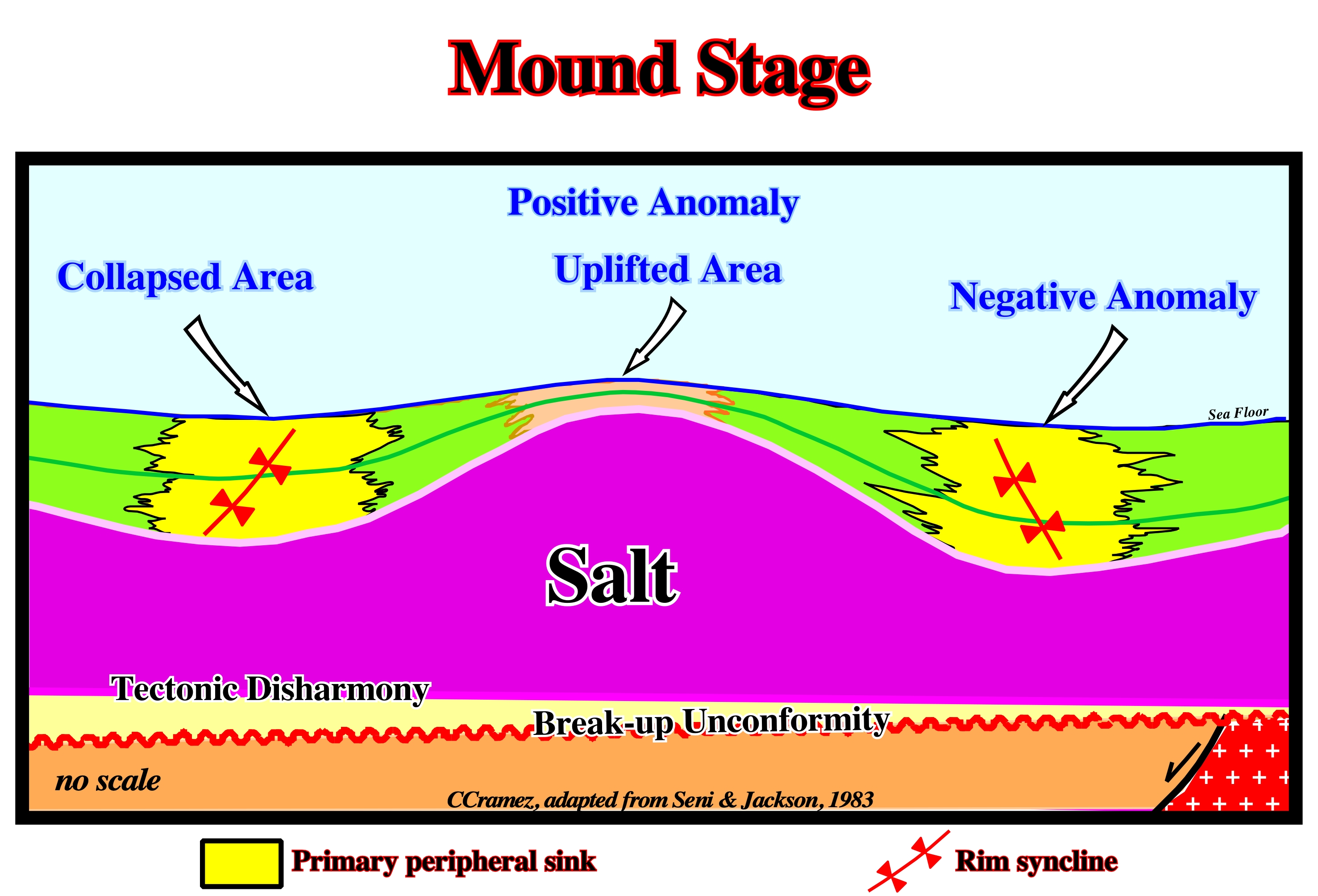
In a mound stage, the coeval overburden interval shows two depocenters on the flanks of the salt mound and relatively condensed stratigraphic section at top the mound. In this sketch, the overburden is synchronous with the salt movement.
Movement Cell (Jackson, M.P.A. and Talbot, C.J.,1991)
The volume containing closed loops of streamlines or stream surfaces in an overturning system of source layer and overburden.
Mushroom Diapir (Jackson, M. P. A., 1995)
Salt diapir having a broad bulb fringed by one or more laterally flattened, pendant skirts of deformed evaporates that envelope the stem of the diapir. Both the skirts and infolds they surround are downward-facing.
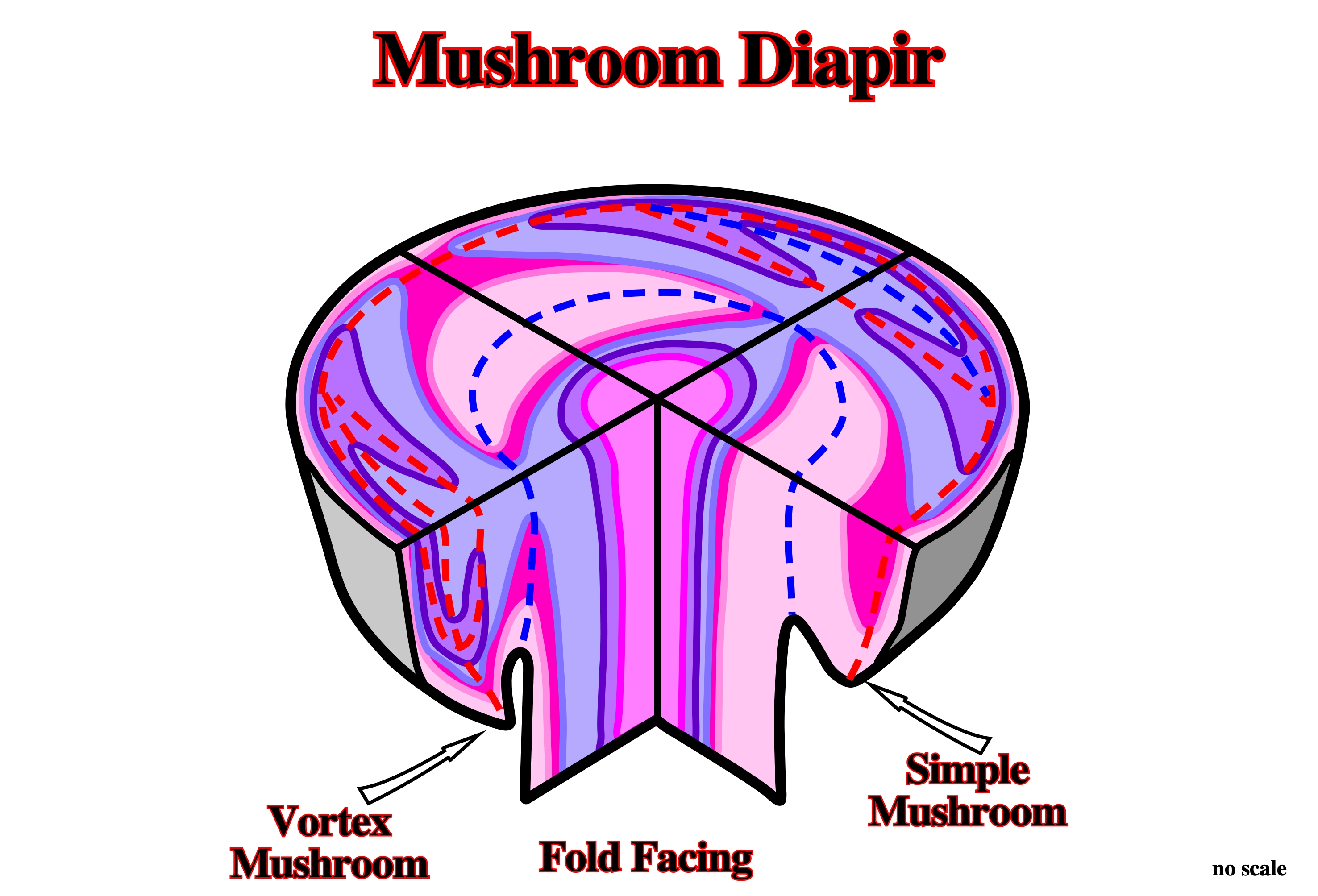
Due to its complex geometry, mushroom diapirs can be identified on the ground or with good seismic 3D data, particularly on time slice.
Mushroom Structures (Jackson, M. P. A., 1995)
The term mushroom has long been loosely applied, particularly, to diapirs shaped like bulbs, despite the fact that actual mushrooms are not shaped like bulbs. Truly mushroom-shaped structures have a bulb fringed by one or more pendant peripheral lobes. See: Mushroom Diapir.
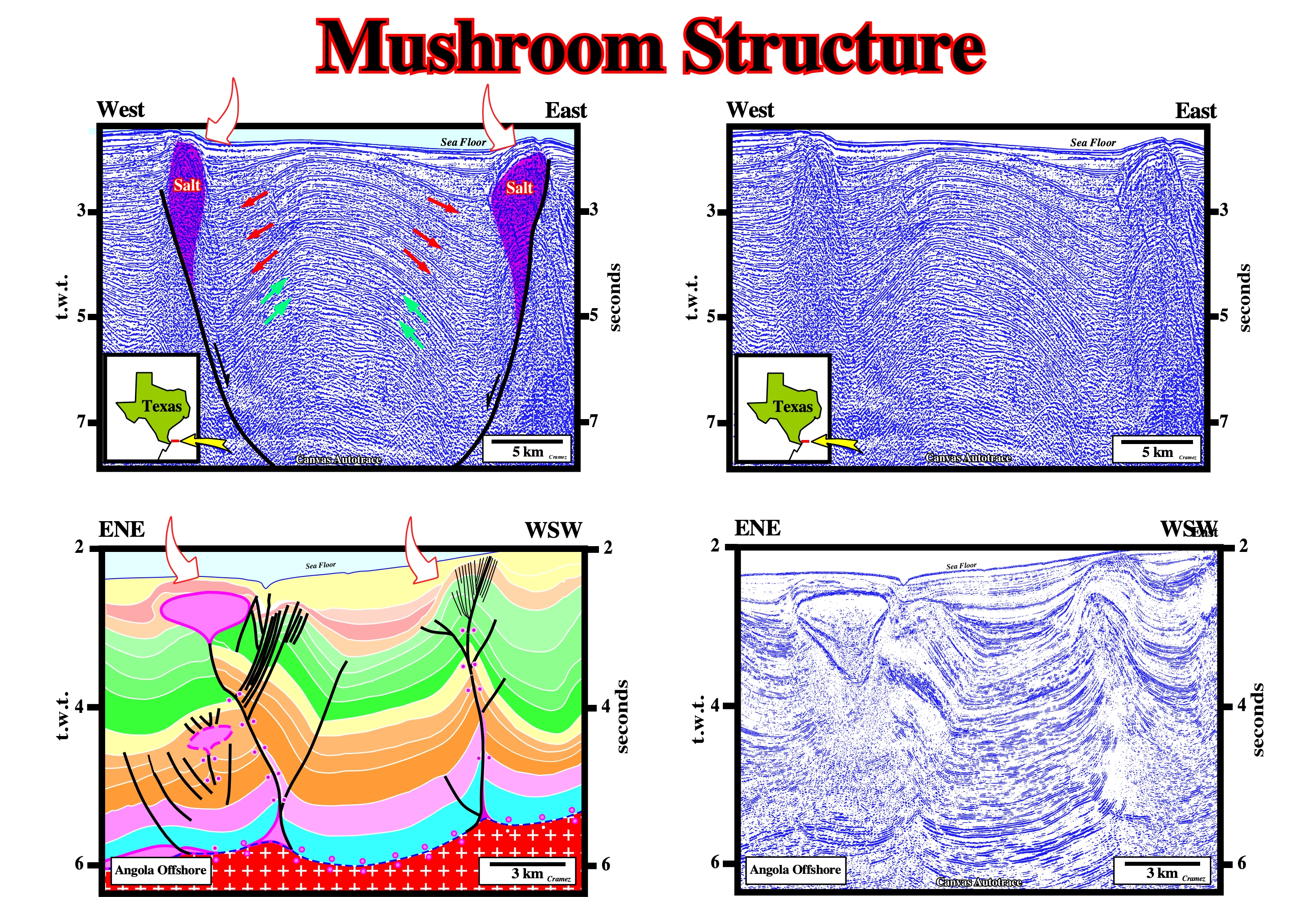
The salt structures illustrated on these tentative geologucal interpretation of the Canvas autotraces are often called mushroom structure in spide of the fact that are far from having mushroom geometry. Actually, since a salt structrure has a bulb geometry, a lot of geoscientists call it mushroom structure.